
Abstract
An ultrasonic vibration–assisted micro-milling with horizontal vibration of workpiece is investigated in this article. A vibration platform with maximum amplitude of 15 μm based on universal ball support structure is designed and built by our group. Titanium alloy TC4 and aluminum alloy 6061T6 were chosen as workpiece material. Series of slot-milling experiments were conducted with and without vibration at different amplitudes and feed rates to explore the effects of vibration on the micro-milling. Experiment results showed that ultrasonic vibration can effectively reduce milling force by 12% and 17%, respectively, for aluminum alloy 6061T6 and titanium alloy TC4 compared with that of conventional milling and hence leading to a better machining accuracy and longer tool life. Furthermore, the effect of ultrasonic vibration on titanium alloy is much more obvious. The topographies of machined surfaces also showed that ultrasonic vibration can reduce surface defects and machining marks and thus improve the surface quality for both 6061T6 and TC4. Besides these, it is worth to be noted that ultrasonic vibration leads the size effect point appear at much lower feed rate than conventional milling, which means vibration brings a change to machining mechanism and delays the appearance of micro-milling.
Introduction
Current product developments along with a rising need for micro devices demand for flexible and economic ways to manufacture micro-structured surfaces.1,2 Micro-milling is one of competitive process for its high geometrical flexibility at short process times for a wide range of materials at comparatively low setup costs. Usually, micro-milling is defined as the downscaling of the conventional milling process involving the use of end mill diameters in the sub-millimeter range and the uncut chip thickness in micro-milling, usually 0.1–200 μm, is comparable in size to the cutting edge radius resulting in large negative rake angles and elastic–plastic deformations of workpiece materials which make micro-machining differs from macro cutting operations. 3 The tool edge radius in micro-machining, comparable in size to the uncut chip thickness, introduces a minimum uncut chip thickness under which the material is not removed but plowed, resulting in increased machining forces that affect the surface integrity of the workpiece. In micro-milling, material removal in micro-milling is often characterized by significant plowing and rubbing compared to conventional scale machining.4,5
For micro-milling, additional difficulties arise from the well-known machining size effect and the fragility of the miniature tool.6,7 The main feature of size-effects in micro-machining is the flow stress of the material which is influenced by different types of size-effects and the most important effect in machining is the increase of the normalized cutting force with decreasing the uncut chip thickness. 8 There are several explanations in literature that relate size effect to the material strengthening mechanisms due to the decreasing number of defects in microstructure, the increasing strain rate at the primary shear zone, the decreasing effect of thermal softening, the effect of strain gradient plasticity at the deformation zones at low uncut chip thickness.9,10 In addition to these, cutting tool edge radius 11 is also considered to explain size effect in machining.
However, some issues such as poor surface roughness, micro burrs on the surface still exist in micro-milling process, which is unfavorable to meet precision requirement of the mini products and shorten their service life. 12 At same time, titanium alloy TC4 offers superb strength properties, corrosion resistance, and biocompatibility and is an ideal material for micro-products. However, this alloy also possesses difficulty in micro-machining often related to high tool wear associated with the reactivity of titanium (Ti) with tool materials and resultant burr formation.13,14
Now, vibration-assisted micro-machining has been applied to a number of processes such as micro-milling, grinding, drilling, and grooving which are found to have the ability to produce better geometrical shape, surface quality, lower tool wear. During vibration-assisted micro-cutting, an interrupted contact is occurring due to the ultrasonic vibration, which leads to the reduction of the cutting forces and tool wear, production of better workpiece surface finish, and longer tool life as well.15,16
Research in the field of vibration-assisted micro-machining (UVAM) of hard-to-machine materials is mainly focused on studying the effect of the control variables of UVAM on the measures of process performance. Lian et al. 17 and Shen et al. 18 investigated an ultrasonic vibration–assisted micro-milling (UVAM) with longitudinal vibration of workpiece and found that the surface of Al6061 processed by UVAM has a smaller roughness value compared to that processed by ordinary micro-milling when choose an appropriate ultrasonic vibration amplitude. Maurotto and Wickramarachchi 19 investigated the effects of frequency in ultrasonic vibration–assisted milling with axial vibration of the cutter. A series of face-mill experiment of 316L in dry conditions were conducted and the experimental results showed competitive results for both surface roughness and residual stress in UVAM when compared with conventional milling especially in the low range of frequency with similar trend for tool wear. Y El-Taybany et al. 20 compared ultrasonic-assisted milling of soda glass with conventional milling (CM) using tool vibration-assisted micro-machining. Results show a reduction of axial cutting force and moment at higher spindle speed and lower feed rate and depth of cut. The application of ultrasonic vibration assistance and cutting fluid demonstrates a significant effect on the axial cutting force and moment. G-L Chern and Y-C Chang 21 investigated the effects of assisted vibration cutting on the micro-milling quality of aluminum alloy Al 6061T6 on a two-dimensional (elliptical) vibrating worktable and found that slot oversize, displacement of slot center, and slot surface roughness could be improved by imposing vibration and the amplitude of the ultrasonic vibration is an important parameter that can be optimized to achieve good surface roughness in this process. H Ding et al. 22 applied two-dimensional vibration-assisted micro-end milling to machine the hardened tool steel (55 HRC and 58 HRC) to study the effects of vibration parameters on the surface roughness and the tool wear. It is found that two-dimensional UVAM can improve the surface roughness and reduce the tool wear compared to traditional micro-end milling, and larger amplitude and higher frequency are useful for the surface roughness improvement and the tool wear reduction.
However, to the best of the author’s knowledge, there is no sufficient knowledge regarding vibration-assisted micro-milling of titanium alloy. In particular, there is no reported study on the influence of vibration on the size effect during UVAM process. In this article, an UVAM with vibration of workpiece is investigated and a systematic design of vibration-assisted micro-milling of aluminum and titanium experiments were conducted on the vibration platform developed by ourselves to explore the effects of vibration parameters on size effect, surface quality, micro-milling forces compared with conventional micro-milling (CM).
Experimental setup
The experiment was carried out on the DMM-22-55 four axes CNC engraving machine and the maximum rotational speed is 150,000 r/min. Different from ordinary micro-milling, here the workpiece is clamped on the worktable of ultrasonic vibration platform rather than on a stationary workstation. Furthermore, micro-amplitude vibrations are produced from the workpiece side, so no modification is needed on the milling machine.
Micro-milling machine tool and ultrasonic vibration platform
The effect of ultrasonic vibration milling mainly depends on whether the ultrasonic vibration system can transfer the ultrasonic vibration output by ultrasonic generator to the workpiece effectively and the energy loss is minimal in the process of transmission. Referring to other researchers,23,24 a horizontal ultrasonic vibration platform based on universal ball supporting structure is designed and constructed by our group to actuate the workpiece vibrate along feed direction. The experimental setup is illustrated in Figure 1. A photo of the vibrator and clamp is shown in Figure 2.
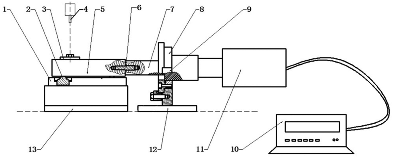
Experimental platform of ultrasonic vibration–assisted micro-milling.

Layout of experiment tests.
As shown in Figure 1, a workpiece is fixed on the ultrasonic vibration worktable. This worktable is supported by four universal ball joints, which connected with installation base by interference fit and one end of the worktable is connected with the amplitude transformer with two headed bolts. Besides this, installation base and force measuring device are threaded together and fixed on the machine table. Hence, high-frequency electrical oscillation from the ultrasonic generator is converted into mechanical vibration about 20 kHz through the transducer and then amplified through the amplitude transformer to transmit to the vibration worktable linked together to achieve workpiece horizontal vibration. Horizontal vibration of the worktable can be realized freely through the rolling of these four universal balls, clearly illustrated in the top view of the setup, as shown in Figure 3.
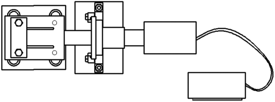
Top view of experimental platform.
To construct this vibration platform, the V6.0 ultrasonic generator with maximum output power of 1 kW from Hangzhou Ultrasonic Equipment Co., Ltd, transducer YP5020-6Z (natural frequency 20 kHz, 2 kW), and stepped amplitude transformer were adopted. In the ultrasonic vibration platform, the vibration worktable is the most central component, which is used to implement vibration and load the workpiece, so the structure design of vibration worktable is very important and simulation optimization of the platform was carried out as shown in Figure 4. Figure 4 gives the finite element meshed model and axial displacement distribution of vibration worktable assembly loaded with workpiece. Combined the simulation results and the actual vibration situation, the size of the worktable was finally determined to be 127 × 110 × 28 mm.

Finite element simulation of vibration worktable assembly with workpiece.
The vibration performance of this vibration ultrasonic vibration system is evaluated using an impedance analyzer PV 70A. The impedance analysis result shows that the vibration platform has good vibration characteristics and the resonance frequency is 19.832 kHz, very close to the theoretical resonance frequency of 20 kHz. The dynamic resistance is 127.24 and the quality factor of 2715.7, which indicate that the assembly of this vibration platform also has a good electro-acoustic conversion rate.
During micro-milling process, different horizontal vibration amplitudes of workpiece can be achieved by adjusting output power of ultrasonic generator to meet the ultrasonic-assisted micro-milling experiment requirement and maximum amplitude is 15 μm under stable operating condition measured using ultrasonic amplitude measuring instrument YP0901B.
Cutting tool, workpiece, and measurement
Two edge end milling cutter of 1.0 mm diameter with carbide steel material was used in this work. The milling cutter, as shown in Figure 5, is with rake angle of 5°, relief angle of 12°, and helix angle of 35°. The actual diameter of cutting edge obtained from Figure 5 is 0.986 mm and cutting edge radius is about 2 μm.

Micro-milling cutter.
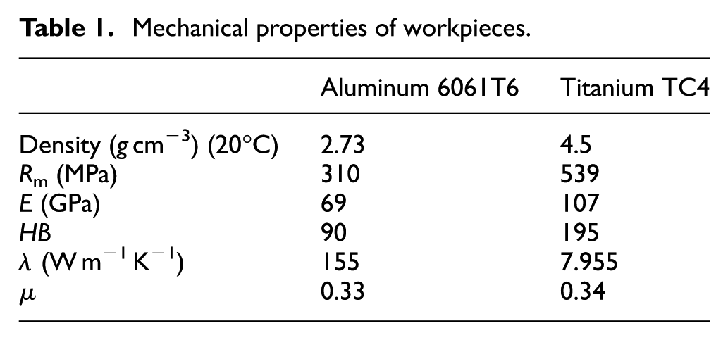
Considering the capacity of vibration worktable, here the size of all workpiece specimens is 90 × 30 × 1.8 mm and each sample prepared with two kinds of materials, aluminum alloy 6061 and titanium alloy TC4. Two through holes on two ends of the specimen are used to fix together with the ultrasonic vibration worktable. To get reliable data, prior to the formal machining tests, a facing process was done for all the specimens to ensure their flatness. The workpiece material mechanical properties are represented in Table 1.
Mechanical properties of workpieces.
Here, Kistler-9257B three-phase dynamometer, equipped with Kislter5019A charge amplifier and a data acquisition system with software DynoWare, is used to collect the three directions (X, Y, and Z) milling force data. Among of them, X is for the feed direction, Y is for the normal direction, and Z is for the cutting depth direction. Usually, in micro-milling process, value of milling force is only a few Newton or even just hundreds micro-Newton.
Surface roughness was measured in terms of mean surface roughness (Ra) and surface roughness tester JB-6C was used to perform microscopic examination of the machined slot bottom. During test, tip of the instrument is kept to contact with the measured surface and surface roughness is measured along the feed direction. Microscopic morphology examination of the machined slot bottom surface was performed using surface morphology observation device OLYMPUS BH-2.
Process parameters
Slot milling experiments here were conducted to find the rules how ultrasonic vibration on the size effect, cutting force, and surface roughness during micro-milling process. Spindle speed, 20,000 r/min, was adopted which meet periodic separation condition between cutting edge and workpiece obtained from simulation result. Axial cutting depth was set 20 μm. At the same time, vibration amplitude of ultrasonic-assisted device was set 0, 2, and 4 μm, respectively, by adjusting output power of ultrasonic generator. Different feed rates of 10, 20, 30, 40, and 50 mm/min, respectively, which corresponding to feed per tooth (fz) 0.25, 0.5, 0.75, 1, and 1.25 μm/r, were used combined different vibration amplitudes were designed to explore the influence of ultrasonic vibration on the milling process, respectively, for titanium alloy TC4 and aluminum alloy 6061T6 workpiece material. Key process variables matrix is shown in Table 2.
Key process variables matrix (A = amplitude).

Experimental results and discussions
In this section, experimental results obtained respectively during CM and UVAM machining are presented. Micro-end mill with diameter of 1 mm was used for dry slot milling and all slot machining lengths are 30 mm. A new tool was used for each experiment. The dynamometer should preheat about 30 min and zero calibration should be finished before each measurement.
During the micro-milling process, the spindle speed is 20,000 r/min combined with the two-edge milling cutter. Hence, the corresponding rotation frequency is 666 Hz. In order to ensure the accuracy of data acquisition, the dynamometer sampling frequency is 1 kHz, higher than the rotation frequency of micro-milling. Furthermore, in order to ensure the authenticity of the experimental results, the sampling time is selected as 0.5 s.
Figure 6 gave the original data diagram of milling force collected which is obvious pulselike, resulting by the intermittent micro-segmented cutting where ultrasonic vibration leads to periodically separation between the cutting edge and the workpiece. Milling forces were collected three times under each experimental condition, and average value of the component milling forces Fx, Fy, and Fz was used for the milling force analysis and resultant force F can be calculated then.
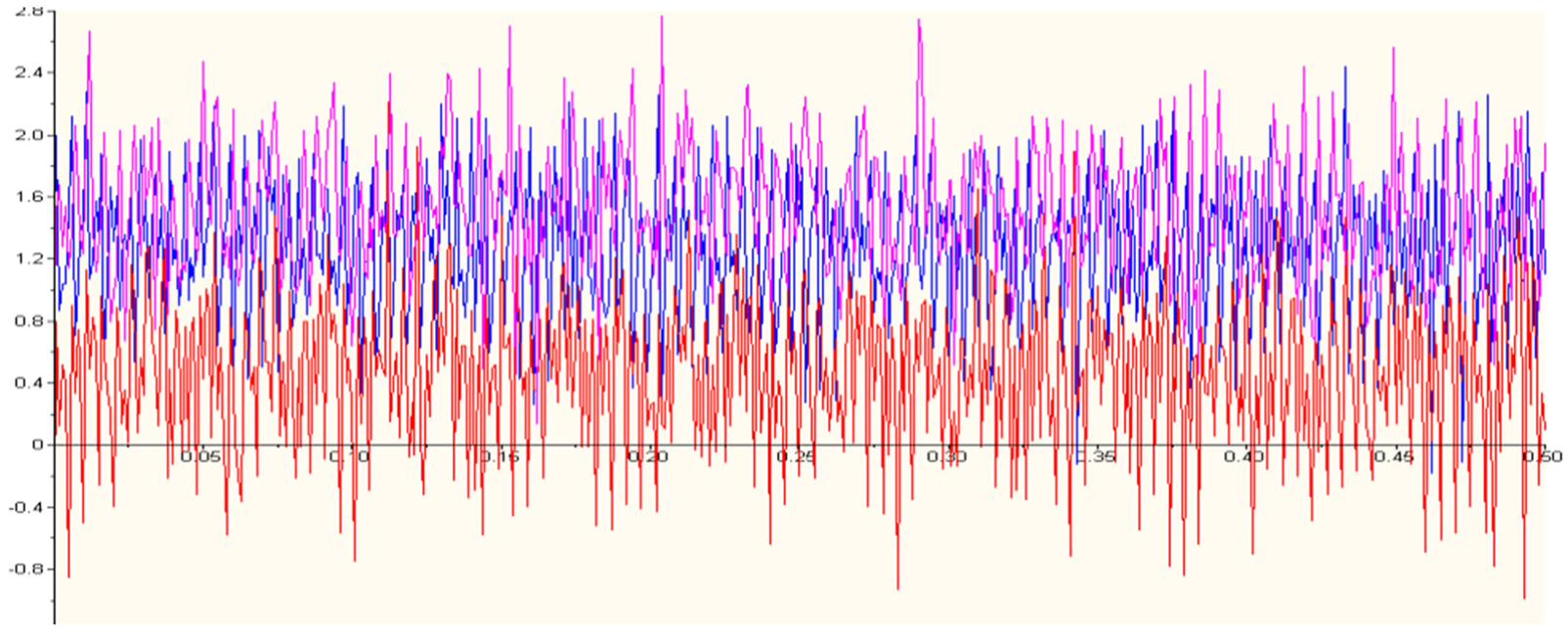
Milling force original data collected via dynamometer.
Size effect point
Component milling forces Fx, Fy, and Fz are compared between 6061T6 and TC4, respectively, under CM and UVAM machining, as shown in Figures 7 and 8.

Milling force of 6061T6 with different amplitudes and feed rates.

Milling force of TC4 with different amplitudes and feed rates.
Relationship between milling force and feed rate under different vibration conditions is shown in Figures 7 and 8. As can be seen from the diagram, the component milling forces both for titanium and aluminum decrease at first and then increase with the increment of the feed rate. So, there is a turning point of variation tendency which here we call it size effect point (using cross symbol to highlight in diagram). On the left side of the turning point, the cutting force increases with decrease of the feed rate, so-called size effect which is also a characteristic distinguishing micro-cutting from macro-cutting. We can also find that the feed rate corresponding to the size effect point for 6061T6 is higher than that of TC4. In general, the grain size of aluminum alloy is usually larger than that of titanium alloy and larger grain size corresponds to the larger minimum cutting thickness during micro-milling process, which results comparatively higher feed rate for size effect point.5, 25
From Figures 7 and 8, we can find that the position of size effect point changes with different vibration amplitudes. Under CM condition, as vibration amplitude of 0 μm, the size effect points for 6061T6 and TC4 were around feed rate of 40 and 30 mm/min, respectively. Under the UVAM condition, the size effect point positions for 6061T6 and TC4 move down to 30 and 20 mm/min feed rate, respectively. Since most researchers attribute the size effect to the enhancement effect under the micro-scale of material, and it can be concluded that all the factors that affect the strength of materials with micro-scale may cause the change the appearance of size effect.7-10 During vibration machining, impulse impact accelerates the generation and propagation of tiny cracks in workpiece material, which reduces the binding force inside grains of micro-scale material during micro-cutting.
Milling force
Component milling forces and resultant forces of aluminum alloy 6061T6 and titanium alloy TC4 in the direction of X, Y, and Z under CM and UVAM conditions are shown in Figure 9.
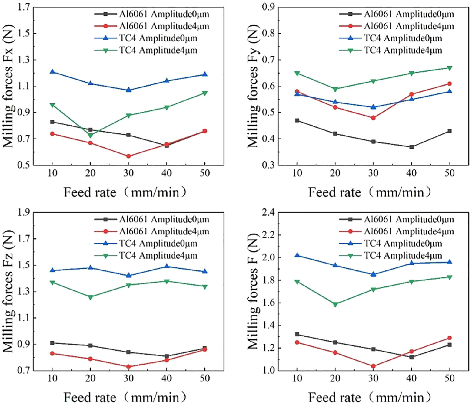
Milling force with different feed rates.
As can be seen from Figure 9, all the component milling forces in three directions of titanium alloy TC4 are greater than that of the aluminum alloy 6061T6, which can be explained by that both hardness and strength of TC4 are greater than that of 6061T6.
On the other side, we can also find the milling forces of TC4 both in X, Y direction showed the same tendency as that of 6061T6, which decrease first and then increase with the increment of the feed rate. However, the milling force in Z direction of TC4 appears serrated, which may be caused by high elastic modulus of titanium alloy. 26 But the general trend is still similar to that of other two directions.
It is further observed that the milling forces of both 6061T6 and TC4 under UVAM condition are lower than that of CM. However, decreasing tendency of TC4 is much more obvious. This may be due to the low thermal conductivity of titanium alloy lead to high temperature near cutting point, and under UVAM condition, the periodic separation between tool and workpiece can be beneficial to the heat dissipation.17-19
Surface roughness
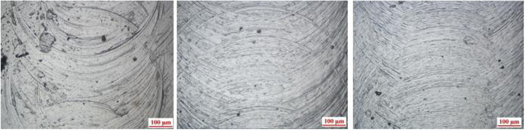
Figure 10 gives the surface roughness of the slot bottom of 6061T6 and TC4 with different feed rates under CM and UVAM condition. Figures 11 –13 are slot bottom images for 6061T6 and Figures 14 –16 for TC4 under different milling conditions. Here, f20 represents that the feed rate is 20 mm/min, f40 for 40 mm/min, and so on. Similarly, A0 represents vibration amplitude of 0 μm, A2 for 2 μm, and so on.

Surface roughness value with different feed rates.

Slot bottom for aluminum under f20 (A0, A2, A4) milling conditions.

Slot bottom for aluminum under f40 (A0, A2, A4) milling conditions.
Slot bottom for aluminum under f50 (A0, A2, A4) milling conditions.

Slot bottom for titanium under f20 (A0, A2, A4) milling conditions.

Slot bottom for titanium under f40 (A0, A2, A4) milling conditions.

Slot bottom for titanium under f50 (A0, A2, A4) milling conditions.
It is clear from the diagram of Figure 10 that the machined surface roughness with vibration is smaller than that without vibration. Hence, UVAM can improve the machined surface quality compared with CM. At same time, their milling qualities are also easy to recognize from Figures 11–16. Without vibration, large feed marks as well as some scratches and irregularities appear on the machined surface. This may be caused by constant cutting tool surface contacting with workpiece materials during the cutting process and acting on the processing surface continuously. In this case, chips and cutting heat cannot be carried away in a timely manner, and plastic deformation is prone to occur on machined surfaces, all of which give reason for surface defects. When ultrasonic vibration is applied, uniform surfaces with fewer defects are obtained. With ultrasonic vibration, the processing surface is micro-segmented and the time of each cutting force is very short. Here, both small chips and cutting heat can be easily reduced or totally eliminated, and thus, more uniform surface can be achieved. 24 On the other hand, ultrasonic vibration of workpiece can reduce yield strength and plastic deformation resistance of the material on a certain degree, which can improve machinability of workpiece material, which all lead to surface integrity improvement. Furthermore, a kind of reciprocating ironing effect can be produced as the workpiece ultrasonic vibration which can also reduce the roughness of the machined surface. But when amplitude of vibration becomes too large, the impact of cutting edge on the workpiece increases which will worse surface integrity of workpiece.
Figure 10 also shows that ultrasonic vibration has a much greater influence on surface roughness of titanium alloy TC4, which can be explained that ultrasonic vibration has a much greater influence on the milling force of TC4. Ra values of TC4 obtained are greater than that of aluminum alloy 6061T6 mainly due to the characteristics of titanium alloy. High elastic modulus and high hardness of titanium alloy make elastic recovery much smaller than that of aluminum alloy after the rake face of micro-end mill cutting through workpieces surface. Meanwhile, low thermal conductivity of titanium alloy leads to poor heat dispersion condition which result high temperature and bring built-up edge phenomenon happen. 26 All these factors contributed to comparatively poor surface roughness of titanium alloy.
With the increase of feed rate, the roughness value for both 6061T6 and TC4 reduced at first and then increased from Figure 10. So, there is a turning point just like milling force. On the left side of turning point, when f = 10 mm/min, corresponding feed per tooth of 0.25 μm/r, which is too low to achieve minimum cutting thickness value, cutting edge is dominated by extrusion and plowing mechanism, which will inevitably increase the friction between the cutting edge and the machined workpiece surface and leads to the worse surface integrity. When f = 20 mm/min, uncut chip thickness closes to the minimum cutting thickness, cutting edge is then dominated by shearing which is beneficial for machined surface quality of workpiece. And with feed rate continues to increase, machined surface roughness increased which is the characteristic of macro-machining.
Dimensional accuracy
The width of the machined slot was measured under Olympus BH-2 microscope, as shown in Figure 17. Each slot is measured three times at different positions, and the average value is used as the width, as shown in Table 3.

Width measurement of the machined slot.
Width of slots obtained under different conditions.

From the results above, ultrasonic vibration can improve dimensional accuracy due to the lower milling force with the addition of ultrasonic vibration, thereby the resulting stress and deformation on the influence of dimensional accuracy decreased. High-frequency vibration also contributes to reduce the dynamic displacement of the cutting tool, which has a similar effect to increasing the stiffness of the process system. All these contribute to the better dimensional accuracy for ultrasonic vibration milling.
Conclusion
In this article, ultrasonic vibration in the feed direction of workpiece is applied to micro-milling the aluminum alloy 6061T6 and titanium alloy TC4. The preliminary research findings include the following:
Experiment results showed that ultrasonic vibration leads the size effect point with much lower feed rate and can effectively reduce milling force by 12% and 17%, respectively, for aluminum alloy 6061T6 and titanium alloy TC4 compared with CM. Furthermore, the effect of ultrasonic vibration on milling force of titanium alloy is much more obvious.
By observing and comparing the topographies of machined surfaces, it is found that ultrasonic vibration milling can reduce surface defects and machining marks and thus improve the surface quality.
Results also showed that ultrasonic vibration can improve dimensional accuracy due to the lower milling force with the addition of ultrasonic vibration, thereby the resulting stress and deformation on the influence of dimensional accuracy decreased.
Footnotes
Handling Editor: Ali Kazemy
Declaration of conflicting interests
The author(s) declared no potential conflicts of interest with respect to the research, authorship, and/or publication of this article.
Funding
The author(s) disclosed receipt of the following financial support for the research, authorship, and/or publication of this article: This work was supported partly by the National Natural Science Foundation of China (grant no. 21576240).