
Abstract
Walking on floors with a varying slope needs more adaptive walking controller against the slope change, since that kind of walking becomes unstable easily without visual information. It may be difficult even for human beings to keep the walking stability without seeing the slope. This work presents a neural oscillator network to generate the patterns for periodic bipedal locomotion, which enable a humanoid robot to adapt to slope change of terrain. Motion trajectories of each limb (each hand and foot) are first defined in terms of periodic functions, the coefficients of which are the output parameters of neural oscillators. Those parameters are determined with the neural oscillator network in cooperation with sensory signals that detect the states of feet in contact with the terrain such that the motion trajectories are scaled for the walking stability. In addition, for the same reason, the neural oscillator controls the trajectories of the center of mass and the zero moment point of humanoid. Using the proposed method, the walking of the humanoid was performed on uneven and uncertain terrain. This application for the humanoid robot may draw some helpful hints on understanding human beings’ walking mechanism against the terrain with a varying slope.
Introduction
In humans or animals, locomotion is one of the most essential and fundamental tasks. However, the neuromuscular mechanism to sustain locomotor stability in bipedal locomotion remains poorly understood since bipedal gait is a complex and nonlinear phenomenon. Hence, stable and robust dynamic bipedal walking has been gaining increasing attention in the robot community, where considerable efforts have been devoted to how to deal with the highly nonlinear nature of robot dynamics and disturbances in uncertain environments. These efforts include such approaches as the zero moment point (ZMP) criterion,1,2 the three-dimensional linear inverted pendulum model, 3 a bipedal locomotion planning, 4 virtual model control, 5 passive dynamic walking 6 and biologically inspired approaches.7–9
Even though recent progress has yielded many notable results with regard to bipedal walking, a natural dynamic walking10,11 or an adaptive walking in viewpoint of human locomotion has not been clearly accomplished yet. For a large number of vertebrates, it is known that instinctive continuous rhythmic movements are produced by central pattern generators (CPGs) in their spinal cord. 12 Specifically, neural oscillators in the unit CPG can endogenously produce rhythmic patterned outputs that can be utilized in generating rhythmic motor movements of bipedal walkers. In addition, neural oscillators can entrain to the sensory feedback, which plays a key role to adapt locomotion in a changing environment. 13 Thus, a biologically inspired locomotion control approach has the potential to produce autonomous dynamic walking of humanoid robots under dynamic environments. The present work involves a new application of neural oscillator networks that enables bipedal robots to autonomously adapt their locomotion to changes in the terrain.
Mathematical descriptions of the neural oscillator were addressed in Matsuoka’s works,14,15 where neurons were proven to generate the rhythmic patterned output in terms of self-oscillations. Taga et al. investigated mutual entrainment of neural oscillators performed by a musculo-skeletal system, which created stable locomotion in a certain environment. Specifically, sensory signals from the joints of a biped robot were fed back to entrain the oscillators.7,8 As a result, the robot became robust against perturbation and was able to climb an upward slope. 9 These attributes were later applied to a 3D locomotion by Miyakoshi et al. 16 In addition to these prior researches, neural oscillators were successfully implemented in dynamic quadrupedal walking by Fukuoka et al. 17 and the control of rhythmic robot arm movement by Williamson. 18
Neural oscillators possess such desirable property as entrainment to the environment. However, it is difficult to design their interconnected relation and feedback pathways. This process entails an intensive and time-consuming effort of manually tuning their parameters to achieve a desired behavior.19–21 Therefore, to decrease uncertainty and nonlinearity in the characteristics of neural oscillators and increase the predictability of adaptation 22 of bipedal locomotion, this work employs changeable predetermined periodic functions for locomotion and a self-stabilizer for stably sustaining the motion of the center of mass (COM) in accordance with various locomotion inputs. Then, differently from conventional approaches,1–9 this enables bipedal robots to walk without information against unknown sloped terrain. An oscillator network with phase adaptation that can compensate for the difference between the predetermined state and the current state of bipedal locomotion is proposed by incorporating the sensory signals that detect changes in the slope of the terrain. In addition, a linear inverted pendulum model coupled to the neural oscillators is employed. The coupled system plays an important role by controlling the trajectory of the COM in phase with the trajectory of the ZMP.
It is verified from the simulation results that the proposed approach exhibits the possibility of an efficient human-like rhythmic locomotion for bipedal walking. Then we examine the validity of the proposed approach with a real bipedal robot in experiments and understand theoretical and feasible principles of human walking.
Control framework
Figure 1 describes the conceptual locomotion control algorithm organized into the neural oscillator network and the locomotion trajectory generator. The neural oscillator network generates the predetermined phases in a time domain. These phases comprise the main phase responding to sensory feedback from the landing foot and the phases of individual limb’s trajectories. The individual limbs consist of two arms, two legs, and torso. The locomotion trajectory generator of individual limbs produces normal trajectories as the function of the phase given from the output of the oscillator network. Then, the joint angle trajectories of individual limbs can be obtained by solving the individual inverse kinematics problems for the trajectory generation of the locomotion except for the joint motion in the rolling direction and the arm motions. In the balance controller, the hip joints are directly controlled using the inverted pendulum model coupled with the neural oscillator. If the main phase is adjusted reflecting the feedback signals from the landing foot, the locomotion trajectory generator autonomously modifies the normal trajectories with respect to the swing motion of two arms and the stance and swing motion of two legs.

The proposed locomotion control algorithm.
Neural oscillator network for phase adaptation
Neural oscillator network
We design a neural oscillator network to realize the phase generator using the neural oscillator of Figure 2. This model consists of two simulated neurons arranged in mutual inhibition.14,15 This model is represented by a set of nonlinear coupled differential equations given by


Schematic diagram of the half-center CPG model.
where xe(f)i is the inner state of the ith neuron which represents the firing rate; ve(f)i represents the degree of the adaptation, modulated by the constant b, or self-inhibition effect of the ith neuron; the output of each neuron ye(f)i is taken to be the positive part of the firing rate and the output of the whole oscillator is denoted as Y(out)i; wijyi represents the total input from the neurons inside a neural network; wij is a weight of inhibitory synaptic connection from the jth neuron to the ith neuron; and we i , wfi are also a weight from extensor neuron to flexor neuron, respectively; the input is arranged to excite one neuron and inhibit the other by applying the positive part to one neuron and the negative part to the other; the inputs are scaled by the gains k i ; Tr and Ta are time constants of the inner state and the adaptation effect of the ith neuron, respectively; and si is an external input with a constant rate.
Properties of the neural oscillator network
Generally, for stable oscillations, if tonic input exists, Tr/Ta should be in the range 0.1–0.5, for which the natural frequency of the oscillator is proportional to 1/Tr. The magnitude of the output signal also increases as si increases. And the minimum gain ki of the input signal enlarges the entrainment capability, because the minimum input signal is needed to be entrained appropriately in the range of the natural frequency of an input signal. In this case, regardless of the generated natural frequency of the neural oscillator and the natural frequency of an input signal, the output signal of the neural oscillator locks onto an input signal well in a wide range. With these properties in changes of the parameters, if the final condition 23 of equation (2) is satisfied and the synaptic weight w is large enough (though it must be small compared with b), neural oscillators exhibit such characteristics as self-organization of the phase synthesis of an outer oscillatory signal, robustness to external and internal parameter changes, and entrainment to environments by means of sensory signals. If there is the connection among the neural oscillators of Figure 2, the network connection gives birth to more complex behavior than a unit neural oscillator owing that changes in the type or the weight of connections between the oscillators allow altering the phase relationships between them

Basically, this network can couple two neural oscillators by establishing four connections weighted w12,v, w21,v, w12,c, and w21,c addressed in equation (1); Figure 3 shows possible connections between two neural oscillators. The colored circles at the end of the connection correspond to inhibitory connections. Thus, if two oscillators are connected vertically, the phase of the flexor neuron, f1, of oscillator 1 will be aligned with that of the extensor neuron, e2, of oscillator 2. This connection implies there will be the phase difference (Figure 4(b)) of ±π between the oscillators. The cross connection between them will have the opposite effect such that the outputs of neural oscillators have same phase (Figure 4(a)). Figure 4 shows such the simulation results according to the connecting condition with the parameters set as Tr = 0.1, Ta = 0.01, b = 20, s = 10, k = 1, w12,v = w21,v = 15 and w12,c = w21,c = 15.

Schematic diagram of neural oscillator networks.

Simulation results of oscillatory signal in (a) phase and (b) oscillatory signal out of phase generated in the neural oscillator network.
Self-adapting locomotion generation
Figure 5 illustrates the kinematic schematic of the humanoid robot employed in this work. In the figure, Ajoint denotes arm joints and Ljoint does leg joints. Ajoint3 and Ljoint1 are engaged in the yawing motion of an arm and a leg. Ajoint2 and Ljoints2, 6 are engaged in the rolling motion. Ajoints1, 4, 5 and Ljoints3, 4, 5 are engaged in the pitching motion. Hjoints1, 2 and Tjoint denote the head joint and the torso joint. The locomotion trajectory generator produces the Cartesian trajectories of respective limbs. Specifically, the swing foot trajectory can be a cycloid and the hip trajectory vaults like an inverted pendulum over the supporting foot.

(a) HOAP robot and (b) kinematic configuration of HOAP robot.
Phase adaptation algorithm
As illustrated in section “Control framework,” the neural oscillator network could have a variety of periodic motions that plays an important role to control the state of phase in individual limbs. Note that stable human locomotion exhibits a coordinated periodic limb movement regardless of a slight change of slope. Therefore, the phase generating oscillator network impacts the protective effect against irregular motor rhythm. Figure 6 represents the proposed phase generating neural oscillator network. The double solid rectangle is the main neural oscillator network that determines the reference phase of the gait cycle through interactions between individual neural oscillators, sustaining the individual motor (limb) phase inputs with each phase shift. Four dashed line-rectangles represent neural oscillators connected for the phase output of each limb. There are inhibitorily connected links between the individual neural oscillators of the opposite limbs based on the connecting rule illustrated in section “Properties of the neural oscillator network.” For instance, the phase signal of the right leg, YR,L, and that of the left arm, YL,A (similarly, the phase of the left leg, YL,L, and that of the right arm, YR,A), are synchronized to the same phase of the generated signal as seen in Figure 6. The phases of two arms and two legs are reversed, respectively. These inhibitory connections are denoted by the dashed dot lines in connections. The line arrows indicate the flow direction of the output of the phase signal interacted between the neural oscillators, and also the dot lines show that sensory signals are obtained from the environment.

Design of the proposed neural oscillator network.
The adjustment of the gait cycle due to the terrain changes will be in effect by the sensory signals. The changes in the predicted phases sensed through the foot sensors result in the change in the reference phase signal generated in the main neural oscillator network. In Figure 6, Y implies a phase signal determined in the neural oscillator network. The sum of YM1 and YM2 generates a reference phase signal incorporating S1 and S2 of sensory signals. This output is additively summed with YL,L, YL,A, YR,L, and YR,A derived from the individual neural oscillator network of the limbs. Therefore, the combined outputs of the phases, adapted to the varying environmental condition, are fed to the locomotion trajectory generator.
In Figure 7, the proposed neural oscillator network is simulated when the flat terrain changes abruptly to an upward slope at 3.85 s. The respective neural oscillator generates the predetermined phases of ±π or 0 as mentioned above, which is designed by networking method shown in Figure 3. To produce the desired output of the phase, the parameters of the neural oscillator should be tuned appropriately. s, k, and w were set to 2π, 4, and 5, respectively.
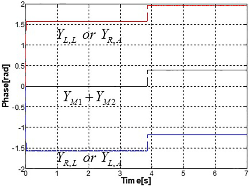
Phase changes when flat terrain changes to an upward slope.
Such phase outputs, YL,L, YL,A, YR,L, and YR,A, of Figure 6 enters the proposed locomotion trajectory generator as indicated in Figure 1. Each trajectory in equations (3)–(5) is the function of the phases as time sent from the neural oscillator networks for each limb given by

Note that “L” and “R” in the first subscript denote left and right, and “L” and “A” in the second subscript do leg and arm, respectively. The pre-specified joint angle velocity, v, required to track the foot trajectories is subject to the dynamics of the coupled oscillators.
Locomotion trajectory generation
For generating appropriate locomotion trajectories, normal trajectories in Cartesian coordinates are provided a priori by the trajectory generator. Normal gait trajectories, based on cycloid function, are given by

where Ax indicates the step length of the normal gait trajectory in the x-z plane (or sagittal plane), and Az does the step height in the same plane. H denotes the height from the ankle joint to the thigh joint (Ljoint2 or 3). The superscripts, “sw” and “st,” note foot trajectories in the swing and stance motions, respectively. Equation (4) holds in the range of 0 ≤ Y < π. In π ≤ Y < 2π, the stance motion is controlled to make the hip move along the horizontal trajectory. Section “Self-adapting locomotion control for a simple bipedal model” addresses how to control bipedal motion. This leg motion is periodically switched at the phase of π. The joint angle trajectories of Ljoints3 and 4 for the pitching motion are determined by solving the inverse kinematics problem. And the joint angle trajectories for the arm motion are designed as the function of the phase of YL,A and YR,A given by

where Aarm denotes the amplitude of the arm swing motion.
In order to precisely control the both legs and arms, a proportional–integral (PD) controller is employed. The torque inputs at the joints are given as follows

where the superscript “i” denotes the ith joint; kP and kD are the ith proportional and derivative gains, respectively. These individual gains kP and kD are set with 2000 and 75.
Posture balancing
In the proposed neural oscillator network with phase adaptation, the sensory feedback is employed to detect changes in the slope of the terrain. The following equation is the sensory signal input to be incorporated in the neural oscillator. 22 Here, if there exists a sensory value, the output of the neural oscillator is instantly converged to the sensory value 24

where
Note that
Specifically, the changes in the slope affect the rolling motion as well as the foot placement associated with the pitching motion. We therefore devised a compensator given by equation (8) which eliminates the difference of the positions between the actual and normal foot placement by checking the final position of the swing or stance state when the phase change happens
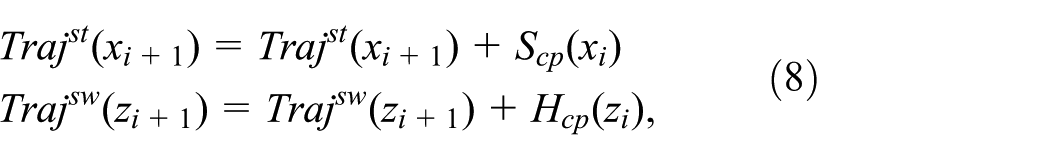
where
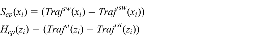
The stride interval is compensated with Scp and the stride height is with Hcp. The posture remains balanced only if the rolling motion of each leg is synchronized in phase with its pitching motion regardless of the changes in the phase of the gait cycle. Since the normal joint motions are pre-designed in the flat terrain environment, the robot motions in the changing environment might result in undesirable interaction forces with its environment. This will bring about the wrong movement of the COM and violate the ZMP criterion.
Self-adapting locomotion control for a simple bipedal model
In bipedal locomotion, the pitching motion should be performed under the single support phase of the rolling motion. In the same way, the rolling motion is accomplished. For attaining the stable single support phases, we consider a simplified inverted pendulum model coupled to such a virtual mechanical component as a spring and damper and the neural oscillator, as seen in Figure 8 for generating an appropriate rolling and pitching motion. The coupled model enables the inverted pendulum to stably move in a frontal and sagittal plane according to a desired ZMP trajectory sustaining the stability of bipedal locomotion.

The proposed control model using a simplified inverted pendulum model for the stable pitching and rolling motion of bipedal robots.
Assuming that θ, the inclined angle between the vertical axis and the pendulum in Figure 9(a) and (b), is small enough and linearized near 0, the dynamic equations of the coupled inverted pendulum in the pitching and rolling direction are given by


Simulation result with respect to the stable (a) pitching and (b) rolling motion of the humanoid robot, (c) plot of the COM motion of humanoid robots in the rolling direction according to the ZMP input.
where x and y are the displacement of the pendulum in the pitching and rolling direction, respectively. l is the length of the pendulum, and u is the position of the massless cart of the pendulum. Note that the subscriptions, “x” and “y,” indicate the pitching and rolling direction in the entire paper, respectively. G is the gravitational acceleration. Fx and Fy indicate the force that should be applied to the COM of the pendulum in the pitching and rolling direction, respectively.
If the desired ZMP trajectory, uy, is given in equation (9), a stably periodic motion of the COM of the pendulum is generated in terms of the coupled neural oscillator with state feedback20–22 (see Figure 9(c)). The parameters of the neural oscillators were set within range of the stable condition addressed in section “Properties of the neural oscillator network” and equation (2). These are described well in Table 1. Here, in order to entrain very quickly an arbitrary uy or ux of Figure 9(c), the natural frequency of the oscillator should be tuned well. 25 Considering one stride per second in normal walking and environmental variety, 1/Tr is set with 8.928 as shown in Table 1. In this case, the natural frequency of the output of the neural oscillator is 6.31 rad/s. Then this enables the oscillator to adapt an unknown sensory input from about 1 to 30 rad/s.
Parameters of the neural oscillator and control model.

COM: center of mass.
In addition, the periodic COM motion corresponding to a ZMP input is achieved in terms of the virtual impedance components. Accordingly, Fx and Fy in equation (9) are given by

where ks is the stiffness coefficient. hx and hy are the output gains of each neural oscillator in the pitching and rolling direction, respectively. P and D are the gains of state feedback, and ip,x, ip,y, iv,x, and iv,y are the gains of the impedance controller. These gains illustrated in Table 1 are properly tuned with describing function analysis 23 and the trial and error method. θo,x and θo,y denote the outputs of the neural oscillators coupled to the COM of the inverted pendulum corresponding to the individual direction. 22 These entrain the COM motion as the sensory feedback signal. Since the stability of the oscillator coupled system depends on the stiffness gain of the state feedback, the value ks has to be carefully tuned. It was set with 100 N/m considering the stable conditions of the neural oscillator and the spring-damper system. Then, the virtual impedance gains are optimized for synchronization between ZMP trajectory and COM motion (see Figure 9). xd and yd denote the desired ZMP inputs.
The current COM position and velocity of the humanoid robot are obtained again by equation (9). For a stable pitching and rolling motion corresponding to an arbitrary ZMP input, Fx and Fy in equation (10) are transformed into joint torques using the Jacobian that needs to be applied to Ljoint3, Ljoint5, Ljoint2, and Ljoint6 of both legs in Figure 5. For example, as illustrated in Figure 9(b), the humanoid robot exhibits stable rolling motion satisfying the desired ZMP. Also the stable pitching motion in Figure 9(a) can be attained in the same way.
Verification through experiments
We performed experiments to verify the proposed locomotion control algorithm using Fujitsu’s HOAP robot (see Figure 5(a)). In Figure 10, the trajectories of the foot joint predetermined by the locomotion trajectory generator are illustrated. The upper and lower figures show the trajectories of the right and left foot joint, respectively. The walking stride is set as 12 cm assuming the flat terrain (each leg strides: 6 cm and the first leg stride: 3 cm). Thus, Ax and Az of equation (4) are set to 6 and 3, respectively, considering kinematic configuration of the HOAP robot’s leg.

Predetermined foot trajectories.
Additionally, we investigate how the adapted locomotion is acquired in the unknown terrain. In Figure 11, it is observed that the foot trajectories are modified to appropriate trajectories adapting to an unknown slope. The foot pressure sensor detects the changing period of foot strike with the ground and sends this information to the main phase generator. In the implemented bipedal locomotion generator, the normal changing period between the periodic stance and swing motion is set as π under a flat terrain as illustrated in section “Phase adaptation algorithm.” Thus, an uphill or downhill slope of an unknown terrain can be checked by the period time sensed from the foot sensor.

Foot trajectories when flat terrain changes to 6° upward slope.
Figure 12 shows the various experimental results on bipedal locomotion on flat ground. Figure 12(a) shows the forward walking of the humanoid robot. Also, various locomotion gaits can be designed based on the proposed phase generator network such as walking backward, turning counterclockwise and clockwise while walking as seen in Figure 12(b)–(d), respectively. This motion can be realized by applying sinusoidal inputs with phase difference, π, to Ljoint1 of the left and right leg. This input should be synchronized in phase with the rolling motion and pitching motion in terms of the phase generator network.

Experiments of HOAP flat terrain (a) forward, (b) backward walking, and (c) turning counterclockwise, and(d) clockwise while walking forward.
Figure 13 shows the results of phase changes in individual limbs with the normal velocity of 1 rad/s. The three lines in the figure correspond to those in Figure 7, respectively. The middle line shows the output of the main phase, and the upper and lower lines show that the phase outputs of the both legs are reversed. The phases for bipedal locomotion are given such that the legs and arms swing in the opposite phase, and the legs and their contralateral arms swing in the same phase. The gait cycle is controlled by the main neural oscillator network. The phase difference remains the same irrespective of changes in the terrain. The phases abruptly jump by about 6° at the instant when the sensory signals, S1 and S2, are fed from the foot pressure sensor (see Figure 6). Thus, locomotion trajectories associated with the pitching motion can be switched appropriately.
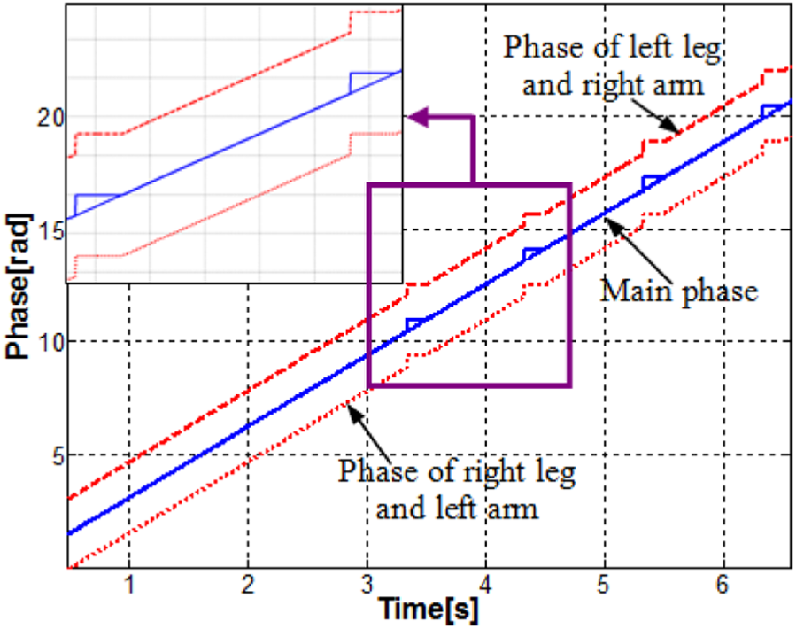
Phase signals from the neural oscillator network.
However, the changes in the pitching phase do not affect the rolling motion that should be synchronized in phase with each other. Therefore, it is important to design the rolling motion compensator in the locomotion trajectory generator. When the phase was jumped at an instant, the jumped phase is kept constant value until the phase returns to the initial set phase. This means that the joint motions not engaged in the rolling motion remain stationary. In the double support phase, the position of the COM should be instantly located at the middle point of both feet, and at the same time the joint angles engaged in the rolling motion should return to zero. In the red dash lined boxes in Figure 14, it is observed that the pitching joints, Ljoint3, 4, and 5, all remain stationary. They are displayed with the blue dashed line, lower blue solid line, and upper black solid line in sequence in the figure.

Joint angle data of the right leg.
Through the simulation results, the main features of the proposed approach are summarized as follows: (1) robust balance control corresponding to the change of a ZMP input, (2) simple control for various bipedal locomotion, and (3) adaptive bipedal walking against uneven slope change. In particular, incorporating the above-mentioned techniques into the locomotion control, we demonstrated that the robot can walk through changing terrain balancing like a human. Figure 15 is the snapshots showing that the robot climbs a 6° slope. The robot climbs the same slope passing through the flat terrain.

Snap shots of gait adaptation to changing slope(6° uphill walking).
Discussion and conclusion
The experimental result, where the HOAP robot locomoted over an unknown slope change (see Figure 15), is well illustrated in Figure 16. The solid line indicates the magnitude of the reaction force measured from the right foot in the z-direction. On the contrary, that of the reaction force of the left foot is drawn by the dashed line. Entire walking stride is set to nine steps as seen in Figure 15 and 16. In Figure 16, it can be observed that the HOAP robot walks stably with autonomous adaptation ability. A change of the swing and stance motion is performed almost every 1 s repeatedly without the double support phase. However, since the robot faces with an unknown slope on walking of the third step, the foot sensor is activated faster than the predicted time as seen in Figure 16. Then it causes the double support phase in walking. As shown in Figure 14, the motion of the COM is specifically controlled under the double support phase so that the COM position is shifted to the center position of both feet. After controlled, the locomotion starts from the other leg. Such motions are performed repeatedly till about 9 s because the inclined angle of the slope remains unchanged.

Pressure sensor value on the left and right foot in the z direction.
Note that the phase difference and the phase relation of each limb’s motion for stable rhythmic walking should be maintained and synchronized as mentioned in sections “Control framework” and “Neural oscillator network for phase adaptation.” In locomotion, the rolling and pitching motions are performed simultaneously and the phases of these motions are mutually connected. If the foot contact of the swing leg does not occur as expected owing that the swing motion and the pitching motion is activated in phase, critical problems with respect to walking stability caused by the rolling motion may arise. Therefore, the control algorithm for the rolling compensation is required as shown in Figure 14, since rhythmic walking is disturbed when walking on an unknown terrain if there is an uphill or downhill slope.
Humans or animals’ walking is controlled by CPGs,12,26 generating rhythmic signals that activate their limbs. The CPG is sensitive to external sensory signals that come from peripheral nerves and it modulates the driving signals in response to sensory signals. With this, they can immediately adapt to environmental changes and disturbances. Although they meet the slope change without visual information, rhythmic motions of individual limb for walking are continued smoothly. The idea of the proposed locomotion control algorithm is related to a CPG-based walking theory of vertebrate animals. It is observed through the results shown in Figure 15 and 16 that gait adaptation of the real robot is possible under the changing slope maintaining the bipedal stability. Figure 17(a) and (b) shows stable limit cycle behaviors of the proposed locomotion algorithm regardless of unknown slopes within an allowable change compared with Figure 17(c) and (d). This implies that the biped control system should be robust over a variety of the ZMP with autonomous trajectory generation (see Figure 18) corresponding to slope changes.

Limit cycle behaviors of bipedal locomotion in the pitching and rolling direction in unknown slope changes when the (a, b) proposed control model and (c, d) only virtual model are exploited, respectively.
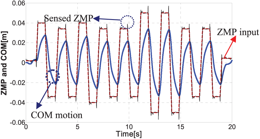
Bipedal locomotion result in the rolling direction in case that unknown ZMP input is changed
Although this approach has potential features that a bipedal robot can locomote over an uneven terrain, the CPG-based walking algorithm presented in this work is far less complex than a walking model of human locomotion. In implementation, the upper body considered as the lumped mass and each body was assumed as a rigid body. Furthermore, the differences between the real and simulation model such as dynamics property, friction, and ground condition cause an unexpected stability problem of bipedal locomotion. Specifically, these problems become more critical in the bipedal locomotion on inclined floors. Hence, we are currently researching on a method for enhancing more adaptive and self-generated motor patterns in terms of the CPG and passive ankle joint system. These efforts will provide further insight into how rhythmic walking of humans or animals can be sustained irrespective of unknown environment changes.
Footnotes
Handling Editor: Yong Chen
Declaration of conflicting interests
The author(s) declared no potential conflicts of interest with respect to the research, authorship, and/or publication of this article.
Funding
The author(s) disclosed receipt of the following financial support for the research, authorship, and/or publication of this article: This research was supported by the Basic Science Research Program through the National Research Foundation of Korea (NRF) funded by the Ministry of Education (2017R1A2B3010336) and by the Research Grant of Kwangwoon University in 2018.