
Abstract
Space grippers are the key devices for accomplishing space non-cooperative target capture, which has a great significance for satellite services and space debris removal. This article proposes a novel mechanical gripper device for the capture of aluminum honeycomb panels of non-cooperative satellites. The gripper was modeled and assembled in the three-dimensional modeling platform UGNX. The model was imported into the simulation software ADAMS. ADAMS is capable of analyzing the kinematic feasibility of the gripper model. Collision and penetrating power analysis of the mechanical claws into an aluminum honeycomb plate were carried out in LS-DYNA. Through non-vertical piercing experiment, the maximum approaching angle tolerance is 10°. The established rigid connection can withstand a destructive force greater than 1000 N. A prototype of the mechanical gripper is built. A ground test was carried out with this prototype, in which a test-platform simulated the space microgravity environment. The results certified that the prototype could reach the target at a relative speed of 0.5 m/s and then quickly complete the grabbing motion and establish a rigid connection. The experiment shows that this mechanical gripper can accomplish the task of repeatedly capturing the surface of non-cooperative space satellites.
Introduction
As early as the 20th century, the importance of space target capture was noticed by the national organization for servicing satellites in orbit, clearing space debris and capturing other non-cooperative targets.1,2 Non-cooperative target capture technology is of great significance for space security. Such technology also has significant value in military and civilian areas.3–5 For a robot to capture a space target, a mechanical gripper is an essential component to successfully capture and establish a connection with the object.
To accomplish the space target capture mission, scientists from all countries have carried out a great deal of studies of this issue and have put forward various effective solutions. Currently, space target capture devices mainly include the following four categories, based on the device structure: fingers structure, net rope structure, anchor structure, and adhesion structure.
The fingers structure, similar to hand claws, mainly include two-, three-, and multi-fingered structures. In 1993, the Columbia Space Shuttle successfully conducted the first long-distance control pilot of thein-vehicle robot arm (ROTEX).6,7 ROTEX consists of a mechanical arm and two fingers with multi-sensor integration. 8 The hand claws are able to operate flexibly on parts outside the capsule. An important feature of the ROTEX gripper is multi-sensor integration, which is a highly integrated and intelligent sensor system. At present, the more successful out-vehicle two-finger gripper is the Japanese ETS-7 robot gripper.9,10 With seven degrees of freedom, this gripper can trap satellites that are in the wrong orbit in a more flexible manner. In 1998, the active satellite and target satellite accomplished two space docking demonstrations and successfully achieved out-vehicle gripping with a manipulator. The manipulability measure for a multi-arm space robot is more complex than that for a single-arm space robot. 11 The underactuated manipulator developed by NASA has three fingers, two motors, and 10 degrees of freedom, allowing flexible operation of the International Space Station (ISS). 12 A typical multi-finger claw is the NASA Robonaut hand robot claw, which is a 14-degrees-of-freedom dexterous hand with five fingers. The Robonaut can accomplish more complex tasks than other grippers can. 13 Fingers structures are complicated and mainly used for grasping, operating, or servicing specific parts inside or outside the cooperation target.
The net rope structure mainly includes one or more mechanical net. In the 1990s, the European Space Agency (ESA) proposed the Geostationary Servicing Vehicle (GSV) for the docking of non-cooperative satellites in geostationary orbit (GEO). Tether-nets are one of the more promising methods for the active removal of space debris. 14 In 2002, DLR (Deutsches Zentrum für Luft-und Raumfahrt) conducted a feasibility study to capture synchronized non-cooperative satellites in Earth orbit and proposed a novel approach—a rope net capture device.15,16 The net area is 10 m × 10 m, and the maximum traction rope length is 60 m. This net can capture space non-cooperative satellites by launching a flexible flying net. When the target on the apogee of the satellite orbit enters the effective distance of the satellite system, the flying net will be launched along the target and then expand and envelop the target. 17 The net rope structure can arrest various shape targets. However, it is difficult to release the target, and the net cannot capture targets repeatedly.
In China, the Harbin Institute of Technology completed the design of an anchor positioning system for asteroid landing. 18 The system is composed of five main parts: the anchor body, propeller mechanism, cable box, distaff mechanism, and the distaff locking and unlocking mechanism. The principle of the device is that high-pressure gas pushes the piston to shoot the anchor body out of the tank, piercing the asteroid surface, and drawing in the target with the traction rope. Certainly, the anchor will be used for capturing non-cooperative satellites. However, the structure and function of non-cooperative targets can be damaged by this approach. In addition, the anchor is disposable and can only be used once.
In the United States, a team consisting of the JPL (Jet Propulsion Laboratory) initiated research on imitating the gecko gripper for space target adhesion in orbit. 19 The analysis suggests that the structure of the gecko gripper is a nanosucker array. A flexible connection can be established by adsorption on the satellite surface. Compared with net rope structure, gecko gripper can release the target at any time. However, what should be considered is that the adsorption force is not sufficient to established rigid connection between the target and gripper.
In this article, the research proposes a new mechanical gripper that can be operated independently for the capture of aluminum honeycomb panels of space non-cooperative satellites. The mechanical gripper can achieve target capture by grabbing the aluminum honeycomb plate of a satellite’s surface to set up a rigid connection. At the beginning of the research, the mechanical gripper was modeled and assembled in the three-dimensional (3D) modeling platform UGNX. After that, the established model was imported into the simulation software ADAMS to analyze the kinematic feasibility. The collision and penetrating power analysis of mechanical claws and aluminum honeycomb plates were completed in LS-DYNA. The main parameters of the spindle spring and motor are determined by optimizing and selecting the materials, structure, shape, and puncture angle of the claws. Finally, a prototype of the mechanical gripper was developed, and a ground test was completed. The results certificated that the prototype can reach the target at a relative speed of 0.5 m/s and then quickly complete the grabbing motion and establish a rigid connection.
Characteristics of the aluminum honeycomb panel
Most of the surface area on a satellite is covered with aluminum honeycomb structure board for a thermal insulation barrier, and this is a common construction. Thus, in this article, the aluminum honeycomb panels on the surface of non-cooperative space satellites are taken as the target for capture.
It is necessary to analyze the relevant parameters and characteristics of the aluminum honeycomb panel. Figure 1 is the structure of aluminum honeycomb panel after measurement. The overall thickness is 26 mm, the upper and lower aluminum alloy plate thickness is 0.3 mm, and between them is the honeycomb core. The honeycomb grid is hexagonal with a 5-mm side length and wall thickness of 0.03 mm. The aluminum alloy is 2A12T4 hard aluminum.
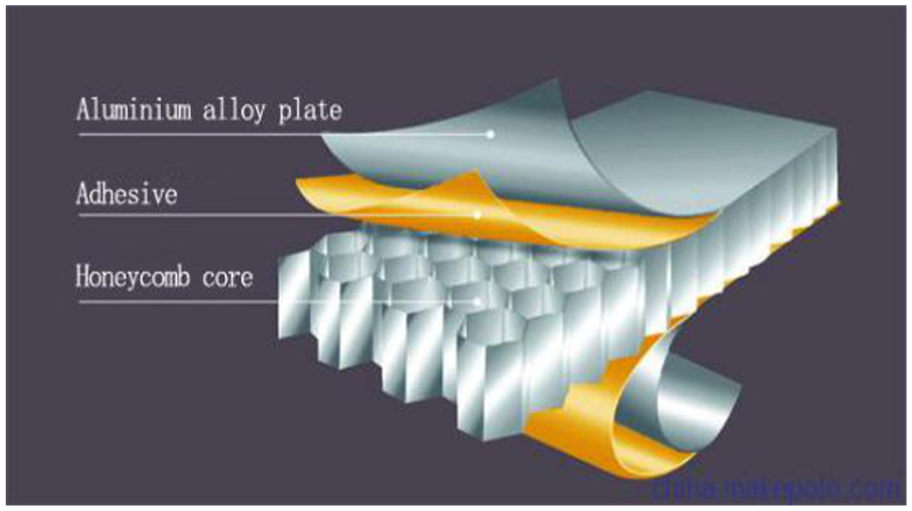
Structure of the aluminum honeycomb panel on the satellite.
Mechanical design of the gripper
Modeling of the gripper
UGNX is the CAD/CAE/CAM integration software of Siemens, with a powerful parameter design function, and it is extensively applied in designing and manufacturing. 20 The entire robot gripper is modeled and assembled in UGNX.
Figure 2 is an explosion diagram of the mechanical gripper. Figure 3 shows the sectional view of the gripper. The figure depicts the details of the external and internal structures of the robot gripper.

Explosion diagram of the gripper.

The assembly drawing of the gripper.
Depicted in Figure 4 is the prototype of the mechanical gripper, the dimensions of the mechanical gripper are 175 mm × 80 mm × 80 mm. Its weight is 1.75 kg.

The prototype of the gripper.
Working principle of the gripper
The gripper can complete the entire operation process from approaching the target, to contacting the target, to grasping the target, and finally to releasing the target. In the process of operation, the mechanical gripper has four states: the first is spring compression, the second is a preparatory phase, the third is target grabbing, and the fourth state is target release.
As Figure 5 shows, the screw is rotated by the motor forward rotation. Due to the action of the screw drive, the tray will mesh with the screw moving up. At the same time, the spindle spring is compressed between the upper board and sliding plate. The claws are driven by the link mechanism and are opened.

Compression of the spindle spring.
As shown in Figure 6, when the tray moves to the top, it triggers the stroke switch. Then, the motor rotates in reverse and moves the tray to the bottom. The springs are compressed by the locking mechanism, storing the spring energy, and the claws remain open; then, the motor reverses rotation and moves the tray to the bottom, where there is another stroke switch. When the screw touches the stroke switch, the switch sends out an impulse signal to the control system, stopping the motor. The entire gripper system then goes into a preparatory phase state.

The preparatory phase state.
Figure 7 presents the buffer foot-triggered state. When the buffer foot touches the target, the spindle connected to the foot with a knuckle bearing moves up with the foot. The locking mechanism is triggered, the hook is unlocked, the springs release the energy rapidly, and the sliding plate is pushed down by the spring. At the same time, the claws, which are driven by the closed links, puncture the aluminum honeycomb panel quickly and grab the target.

The diagram of buffer foot is triggered: (a) side view; and (b) section view.
The final state is releasing the target. One of the advantages of this mechanical design is that it can release the target at any time. The motor is restarted through the controller. The screw is rotated by the motor forward rotation, and due to the action of the screw drive, the tray will mesh with the screw moving up. The spindle spring is compressed again. The action of the mechanical gripper is similar to the first step. The difference is that at this point, the claws have penetrated the target surface. Therefore, the claws will open and pull out of the punctured aluminum honeycomb board.
Key components design
Design of the claw
The claw is one of the core components of the entire gripper; therefore, there was a comprehensive analysis and optimization of the length, shape, hinge point position, and cross-sectional shape of the blade in detail.
Figure 8 depicts the claw design. As shown, the claw is a bilateral blade. The function of the outside blade is for cutting the aluminum honeycomb panel surface. The arc blade (inside blade) is used for providing a grabbing force when the claw pierces the aluminum honeycomb core.

The claw structure diagram.
Figure 9 shows the design of the claw size in detail. The red circles are the rounded cutting edges whose radii are 60 and 53 mm, respectively. The claw thickness is 2 mm.
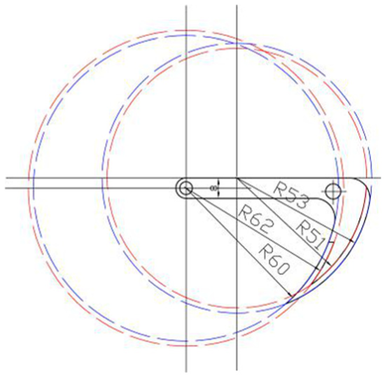
Design of the claw size.
By driving the spring force, the claws should quickly complete the activity of repeatedly penetrating and puncturing the aluminum honeycomb panel. Therefore, the claw material should have the following characteristics: high hardness, high wear resistance, sufficient toughness, and good craftsmanship.
In the experiment, two kinds of materials were selected: iron-cemented tungsten carbide (WC) and high-speed steel (W6Mo5Cr4V2). From the experiment, it was found that iron-cemented tungsten carbide’s bending strength and toughness are lower than that of the high-speed steel. In addition, WC is harder and more brittle, hence fracturing often during the experiments. In contrast, W6Mo5Cr4V2 has both higher strength and toughness. Therefore, high-speed steel was selected to make claws.
Design of the spindle springs
The function of the spindle spring is to store energy and then release it rapidly in order to drive the claws to puncture the aluminum honeycomb board. According to the LS-DYNA simulation results, the spring force preload is F1 = 0–20 N. After that, the spring reaches maximum compression, namely, Fmax, chosen as 400 N. Table 1 presents the spindle spring parameters. The material selected is 60Si2Mn.
Compressed spring parameter table.

Kinematic simulation
To provide the basis for the design of the mechanism and reveal the reflections of workload, the software ADAMS was used for kinematic simulation experiments.
To facilitate the calculation of the kinematics simulation models, fasteners such as bolts, nuts, and washers were replaced by connections and constraints in ADAMS. The material properties of each part were defined. Then, as shown in Figure 10, the 3D assembly model of the gripper was imported into ADAMS. The entire simulation process time was set to 5 s, and the number of simulation steps was 500. The spindle spring is replaced by a spring forces in ADAMS.

Simulation in ADAMS: (a) initial state; (b) fastened state; (c) Tray moves down; (d) ready state; (e) grabbing state; and (f) releasing state.
Figure 10(a) is the initial state of the gripper. At this moment, the spindle spring (stiffness coefficient is 3 × 10⁻² N/m and damping coefficient is 7.4 × 10⁻³ N s/m) is free. The tray is in the lowest position of the spindle screw. Above the tray is a plate that can slide along the main axis. The claws are closed.
Figure 10(b) shows the fastened state of the gripper. At step time from 0 to 0.16 s, the spindle screw is rotated by the positive motor rotation. Then, due to the action of the screw drive, the tray that meshes with the screw moves up until the tray touches the travel switch and stops. The tray moving up can push the slider board up, and the spindle spring is compressed. As the slider board moves, it will open the claws with the links that are hinged at the slider board and the claws. At 0.16 s, once the position-limited switch (it is replaced by a position sensor in ADAMS) is touched, motor will be stop and turn in the reverse direction.
As shown in Figure 10(c), the tray moves down to the bottom at this step. Due to the reaction of the compression spindle spring, the slider board will also move down slightly. We notice that there are three hooks on the slider board that can hook on the locking mechanism. Then, the tray should still move down to the bottom and trigger another position-limited switch on the lower board.
As shown in Figure 10(d), the gripper remains open, and the entire structure is in the ready state. Finally, as indicated in Figure 10(e), from 1 to 1.07 s, the gripper will apply a trigger force F = 30 N to the cushion foot and the buffer spring (stiffness coefficient is 2.7 × 10⁻² N/m and damping coefficient is 6.7 × 10⁻³ N s/m). The locking mechanism is then opened. Once the buffer foot that connects the spindle through the ball bearings touches the target, the spindle moves upward through the hollow screw. Without the locking mechanism, the spindle spring is restored to the original length and releases energy. The slider board will move down quickly along the spindle driving the spindle spring. Then, the claws close quickly and pierce the surface of the aluminum honeycomb panel.
In Figure 10(f), the motor is switched on again, and the tray moves up. The tray will push the sliding board up together with it. Driven by the connecting rod, the claw opens and pulls out from the honeycomb panel. The target is then released. At the same time, the tray will move to the top of the screw. The release process is complete.
During the simulation, a marker named marker_282 is marked at the tip of the claw. A speed sensor is set on Marker_282. Figure 11 shows the speed of the marker_282. The red curve is the velocity of the X-axis direction during claw movement. The blue curve is the velocity of the Z-axis direction during claw movement. The maximum speed of the claw is 27.52 m/s.

The curve of the claw tip speed.
There was no interference between various components of the gripper in the ADAMS simulation. The mechanical structure could work smoothly and achieve the prescheduled action.
Penetration simulation
LS-DYNA based finite element meshing
LS-DYNA is good at calculating analysis penetration and collision problems. The simulation based on LS-DYNA was performed to verify the feasibility and stability of piercing the aluminum honeycomb panel by the gripper. Figure 12 shows the simplified gripper model where some of the parts are omitted to simplify the calculation.

Simplified gripper model in LS-DYNA.
In the calculation of LS-DYNA, the smaller the mesh is, the more accurate the result, but the computer must perform more arithmetic, which will lead to a longer computation time. Therefore, in order to balance the efficiency and accuracy of the calculation, the links were divided by a tetrahedron with side length of 1 mm. However, the key parts of the claws were divided by a tetrahedron with side length of 0.1 mm. Other components were divided by a hexahedron with a side length of 1 mm.
The size of the grid determines the length of the calculation time. The aluminum honeycomb core which is in contact with the claw is divided into finite element mesh with a side length of 1 mm. And, other position of aluminum honeycomb core is divided with grid of side length 26 mm (Figure 13). Similarly, the upper aluminum alloy plate is also meshed (Figure 14). It is divided into a grid with a side length of 0.1 mm which is in contact with the claw. The rest of the mesh has a side length of 50 mm. The entire modeling of the aluminum honeycomb panel is given in Figure 15. This method can not only ensure calculation accuracy but also save calculation time.

Grid division of the aluminum honeycomb core.

Grid division of the upper aluminum alloy plate.

Aluminum honeycomb panel modeling.
Vertical piercing simulation
The gripper approaches the target vertically at a relative speed of 0.5 m/s. The maximum force of spindle spring of the gripper is set to 400 N. The aluminum honeycomb panel is in free-floating state and gravitational acceleration is set to zero. Figure 16 shows the side view and stress cloud diagrams of the gripper piercing the honeycomb panel in different moments.

Side view and stress cloud diagrams: (a) t = 0 s,(b) t = 0.00540 s, and (c) t = 0.03 s.
When the gripper vertically approaches the aluminum honeycomb panel, the claw can pierce the aluminum honeycomb panel and establish a connection in 0.03 s.
Figure 17 demonstrates the speed curve of the slider board and the claws. At time t = 0 s, the buffer foot is in contact with the board surface, and the claws quickly thrust toward the aluminum honeycomb panel. The black curve presents the velocity of the claw. From t = 0 to 0.0054 s, the speed rises to 5300 mm/s in a short time. From t = 0.005 to 0.0085 s, the speed plunges and then fluctuates slightly until it stops at t = 0.03 s. The red curve reveals the speed of the slider board. The speed trend of the slider board is consistent with that of the claw.
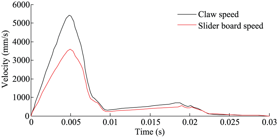
The claw and slider board speed curves.
As indicated in Figure 18, at time t = 0.0045 s, the tip of the claw touches the aluminum honeycomb panel. The maximum grasping force reaches 1120 N at t = 0.0072 s. After 0.01 s, the force fluctuates slightly between 0 and 200 N. The reason is that the interior stress is slowly released due to the complex internal structure of the damaged part of the aluminum honeycomb core. Simulation results show that the contact force is sufficient to pierce the aluminum honeycomb panel.

Curve of contact force between claws and the aluminum honeycomb panel.
Non-vertical piercing simulation
In the non-vertical piercing simulations, the gripper approaches aluminum honeycomb panel in certain deviation angle.
The simulation results for when the angle between the gripper’s main axis and the aluminum honeycomb panel’s normal is 5° are shown in Figure 19.
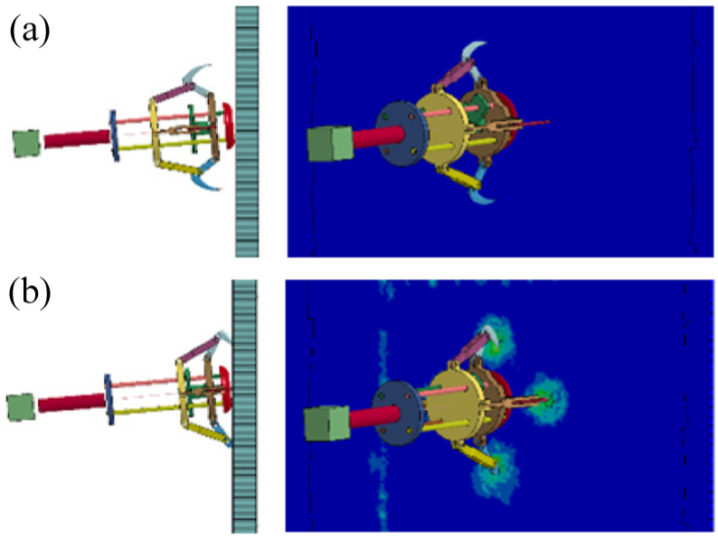
Simulation side view and stress cloud diagrams with deviation angle 5°: (a) t = 0 s and (b) t = 0.03 s.
The lowest surface of the claw touches the aluminum surface first. The final result shows that except for the topmost claw, which shallowly penetrates the surface, the remaining three claws penetrate the aluminum skin completely. The simulation results for when the angle between the gripper’s main axis and the aluminum honeycomb panel’s normal increases to 10° are shown in Figure 20.

Simulation side view and stress cloud diagrams with deviation angle 10°.
In Figure 20, the topmost claw cannot puncture the surface of the plate, and only three claws have pierced the skin of the board. The gripper fails to grasp the panels.
Through different angles deviation of simulation, it was concluded that the gripper can grasp the aluminum honeycomb panel with the maximum approaching angle tolerance 10°. To some extent, it can improve the reliability of the claw operation.
Connection strength simulation
After the gripper grasps the target, it successfully establishes a rigid connection. The state where the gripper captures the target stably is taken as the initial state of the connection strength analysis.
At this point, the spindle spring exerts a residual locking force (more than 20 N) inside the gripper. The separation force F is loaded on the main shaft of the gripper. The applied force F pulls the claw to separate it from the board. By measuring the size of F, it can be verified that the rigid connection established between the gripper and target is firm. As demonstrated in Figure 21, the pulling force on the gripper is gradually increased from 300 to 2000 N.
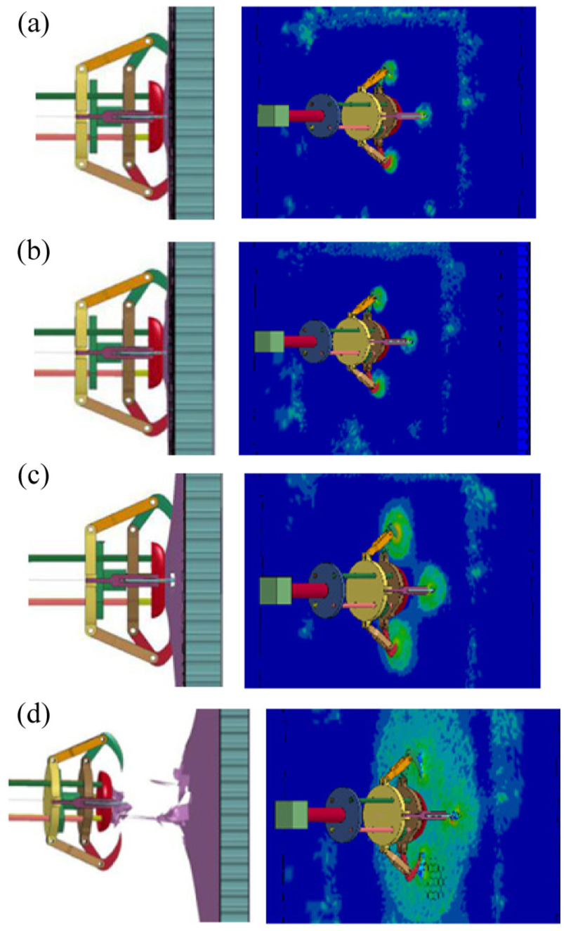
Side view and stress cloud diagrams with pulling force: (a) F = 300 N, (b) F = 500 N, (c) F = 1000 N, and(d) F = 2000 N.
As seen from the highlighted part of stress cloud diagrams, when the pulling force increases from F = 300 N to F = 1000 N, the force of the pulled aluminum skin increases.
Figure 22 shows the gripper speed curve after applying the test force F = 1000 N. When the simulation starts, the velocity fluctuation is relatively large. The maximum speed of the gripper can reach 730 mm/s. However, after that point, the curve fluctuates in a dynamic equilibrium status and slightly relative to zero. In Figure 21(c), the aluminum honeycomb panel does not disintegrate, and the gripper and the aluminum honeycomb panels are guaranteed to feature a stable connection.
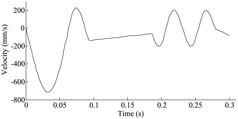
The velocity of the gripper along its axis with time when F = 1000 N.
Figure 21(d) shows the stress cloud under the pushing force of 2000 N. As seen from the simulation, the gripper and the aluminum honeycomb panel are separated. This result means the aluminum honeycomb skin is torn. Figure 23 shows the gripper velocity when F = 2000 N, and the gripper continues moving away from the target.

The gripper velocity when F = 2000 N.
Through the penetration simulation by LS-DYNA, the performance of the gripper was analyzed. When the maximum compression of the spindle spring is greater than 400 N, the claw can pierce the aluminum honeycomb panel and form a stable, rigid connection. The strength of this connection is greater than 1000 N.
Prototype experiment
Motor and control system
The gripper is driven by a 30-W brushless motor (EC16 Ø16 mm) produced by MAXON. The rated torque of the motor is Tm = 8.09 mN m. During the experiment, the DC motor speed is set to 8100 r/min. The selected planetary gear reducer is GP16C by the MAXON company, and its transmission ratio is i0 = 84.
The control system consists of a motion control module, motor drive module, power module, and Controller Area Network (CAN) communication module. The motion control module uses a 32-bit processor; the features of the control module include receiving the host computer’s motion instruction, detecting the sensors signal, and controlling the motor movement of the gripper. The motor drive module executes the position loop control for the motor. The power module supplies power for the motor, circuits, and sensors. The CAN communication can complete the communication of the motion control module, motor drive module, and upper computer.
Test-platform design
To verify the feasibility of the mechanical design in the space microgravity environment, a test-platform was established (Figure 24) for performing ground experiments. The test-platform was set up with an aluminum alloy framework. The horizontal rail was installed on the top of the main frame, and it can drive the gripper close to the aluminum honeycomb panel. The aluminum honeycomb panel is fixed on the main frame. The gripper is hung by nylon ropes. The gripper can approach the target with different horizontal speeds. There is no gravity along the horizontal direction. Adjusting the length of the ropes can change the approaching angle. At the end of the gripper is the additional weight.
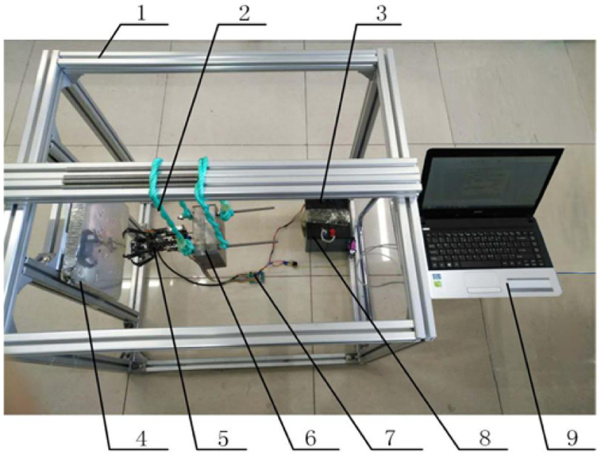
Test-platform.
Experimental results
In Figure 25(a), the gripper approaches the target (aluminum honeycomb panel) at a relative speed of 0.5 m/s and collides with the target, and the panel provides a reverse force to the buffer foot for triggering the locking mechanism to open.

Prototype experiment: (a) initial state; and (b) grabbing state.
As seen from Figure 25(b), all four claws successfully penetrated the aluminum honeycomb plate and formed a stable rigid connection with the target.
Conclusion
In this article, the aluminum honeycomb panel, which is a common external structure on spacecraft and satellites, is seen as the target of capture. The study proposes a new mechanical gripper for a non-cooperative space target-capturing device. This gripper is different from previous studies in the way that it can repeatedly capture and release the non-cooperative space target. First, the gripper was3D-modeled in the UGNX software. Then, the gripper was imported into ADAMS for kinematic simulation. After that, it was imported into LS-DYNA for penetration simulation. The prototype of the mechanical gripper was built. Finally, a test-platform was set up, and the space microgravity ground simulation was carried out. The gripper can approach the target with a relative speed of 0.5 m/s. The results show that this mechanical gripper can accomplish the task of capturing the surface of non-cooperative space satellites repeatedly and establish a rigid connection.
Footnotes
Handling Editor: Yangmin Li
Declaration of conflicting interests
The author(s) declared no potential conflicts of interest with respect to the research, authorship, and/or publication of this article.
Funding
The author(s) disclosed receipt of the following financial support for the research, authorship, and/or publication of this article: This research received the financial support from the Fundamental Research Funds for the Central Universities (no. 2015ZCQ-GX-04) and the National Natural Science Foundation of China (grant no. 31670719).