
Abstract
Autonomous underwater vehicle with the ability to generate electricity is an effective solution for detecting the ocean. In this article, a vertical-axis current generator for underwater vehicle is designed. The blades used for power generation are attached to the surface of the underwater vehicle and can be freely deployed and closed so as not to affect the fluid performance of the underwater vehicle. Comparing the experimental data of an ordinary impeller with simulation data, the initial error of the experiment is obtained. Through the experimental method with adjusting the spread angle and blade curvature, the best configuration of the impeller was eventually obtained. When the radian and expansion angle are both set to 120°, the maximum power of 0.599 W can be provided.
Introduction
At present, mankind is facing three major problems of population, resources, and environment. After a competition of lands for thousands of years, the land resources are depleting; we should pay more attention to the ocean for its detection and development. 1 Due to the complex marine environment, underwater vehicles now become more effective detection tools. Underwater vehicles are divided into three types including human-operated vehicle (HOV), remotely operated vehicle (ROV), and autonomous underwater vehicle (AUV).1–3
The main functions of the underwater vehicle are as follows: 4
Laying submarine pipelines and cables, connecting underwater pipelines;
Construction and maintenance of underwater drilling;
To ensure underwater pipeline safety without leakage;
Aerial scanning of the marine environment and video imaging of the seabed environment;
Positioning and recycling of underwater objects, searching for salvage wrecks and shipwrecks;
Scientific investigation and study of the ocean including submarine mapping, submarine exploration, and hydrological research.
HOV cannot be the main detection tool because of its prohibitive costs. ROVs have a cable connected to the mother ship or base station. Detection area of ROV is very small because of cable restrictions. AUV 5 can sail freely in the ocean and work together in order to communicate with each other. But lack of energy is the biggest factor limiting the development of AUV. 6 So AUV with the ability to generate electricity is an effective solution for detecting the ocean.
The biggest bottleneck that restricts the development of AUV is the problem of energy supply. 7 There are many problems in building submarine base stations and recharging them with non-contact charging technology. 3 Due to the limitation of AUV’s control and navigation capabilities, it is still a difficult problem to complete docking with the base station in the deep-sea environment. Power generation through ocean temperature field and salinity field is more suitable for marine glider. 8 In this article, a vertical-axis power generation device is set up for general rotary underwater vehicles. The underwater vehicle can only be stably docked in seawater. 9
The vertical-axis current generator for underwater vehicle is designed. 10 The blade of the water turbine draws on the Savonius-type impeller. A number of scientists have experimentally and numerically examined the effects of various design parameters of Savonius wind rotor. Akwa JV, Irabu K, Alexander AJ and Menet JL. studied the effect of overlap ratio on the performance with a three-dimensional (3D) computation model.11–14 Best of all, this dimension is equivalent to a value between 10% and 15% of the chord size. Menet 15 and Saha et al. 16 have investigated the influence of end plates. For the end plate diameter, the recommended size should be 1.1 times the rotor diameter. With an increase in the rotor bucket number, Saha concluded that the rotor moment is becoming low for angular positions of advancing bucket. 11 Thus, a Savonius rotor with two buckets has a maximum averaged power coefficient. Kamoji et al. 17 also researched the influence of the rotors’ aspect ratio and stages. Kamoji et al. 18 found that a passing shaft could be used as an accessory to provide additional rigidity to the structure of the wind turbine with the reduction of power efficiency. In previous studies, the efficiency of the Savonius turbine has been increased using different optimal manners. D Kumar and S Sarkar 19 and El-Askary WA et al. 20 used obstacle plates or deflectors to optimize the design of Savonius blade turbine. W Tian et al.10,21 optimized the shape of the blade through particle swarm optimization and applied it to highway power generation systems.
In this article, we conducted a series of experiments on the classical Savonius rotor in the towing tank, simplified the physical model, and designed an adjustable experimental device. Then the hydrodynamic experiments were carried out in the towing tank to explore the optimal configuration of the impeller. The influence of the impeller expansion angle and impeller arc on the power generation performance of the device is studied with the rotation of the angular velocity. The best configuration of the impeller was obtained eventually, for the actual design and installation work to provide predictions and guidance.
Application of the power generation device
The vertical-axis current generator of the underwater vehicle is mainly composed of a blade, a steering gear, a position servo consisting of screw and nut, a permanent magnet generator, and a vehicle shell, as shown in Figure 1. When the generator does not work, the blades fit on the surface of the vehicle, as shown in Figure 2.
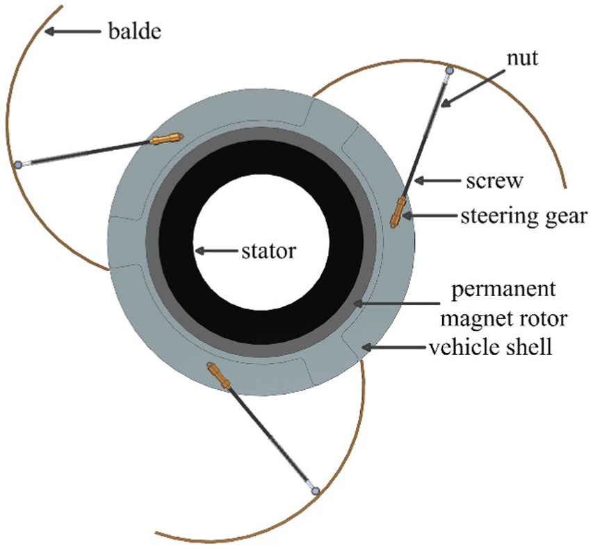
Unfolded drawing of the generator.

View of the non-working state.
The main role of the blade is to obtain the kinetic energy of marine currents. 9 The blades were mounted on the vehicle shell by means of a hinge which is controlled by the position servo system to open and close, its cross section is a circular arc shape. The permanent magnet rotor is embedded directly in the impeller housing. The winding stator is fixed to the main shaft of the vehicle. Compared with the traditional energy supply method, it does not need to be docked with the base station and can independently supply energy for the underwater vehicle.
Its working principle is as follows: When the underwater vehicle needs to be charged, the head of the vehicle releases the inflatable float while the tail left the anchor chain. The vehicle is fixed in the vertical direction. The position servo system then moves the blade to the proper position. Under the action of current, the impeller rotates around the longitudinal axis of the underwater vehicle under the driving of the currents’ torque. The permanent magnet rotor cuts the magnetic induction line to produce the induced electromotive force. After the completion of the charge, the vehicle puts away the anchor chain and the inflatable float. The position servo mechanism works in reverse. Finally, the vehicle continues to work normally. The arrangement of the underwater vehicle is shown in Figure 3.
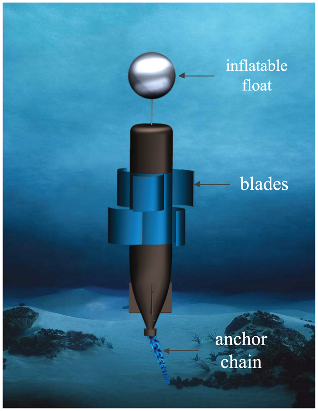
The arrangement of the underwater vehicle.
Design of the experimental device and test facility
The physical model was simplified for experimentation. The experimental equipment includes the following: cap_up, cap_down, the crank joystick instead of the position servo system, impeller, baffle, shell, vertical shaft, and bearing, as shown in Figure 4 and the physical equipment is shown in Figure 5.

The structure of the experimental device.
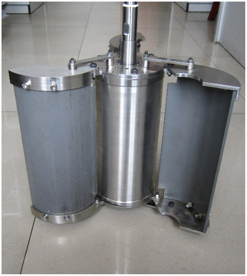
The physical diagram of the experimental device.
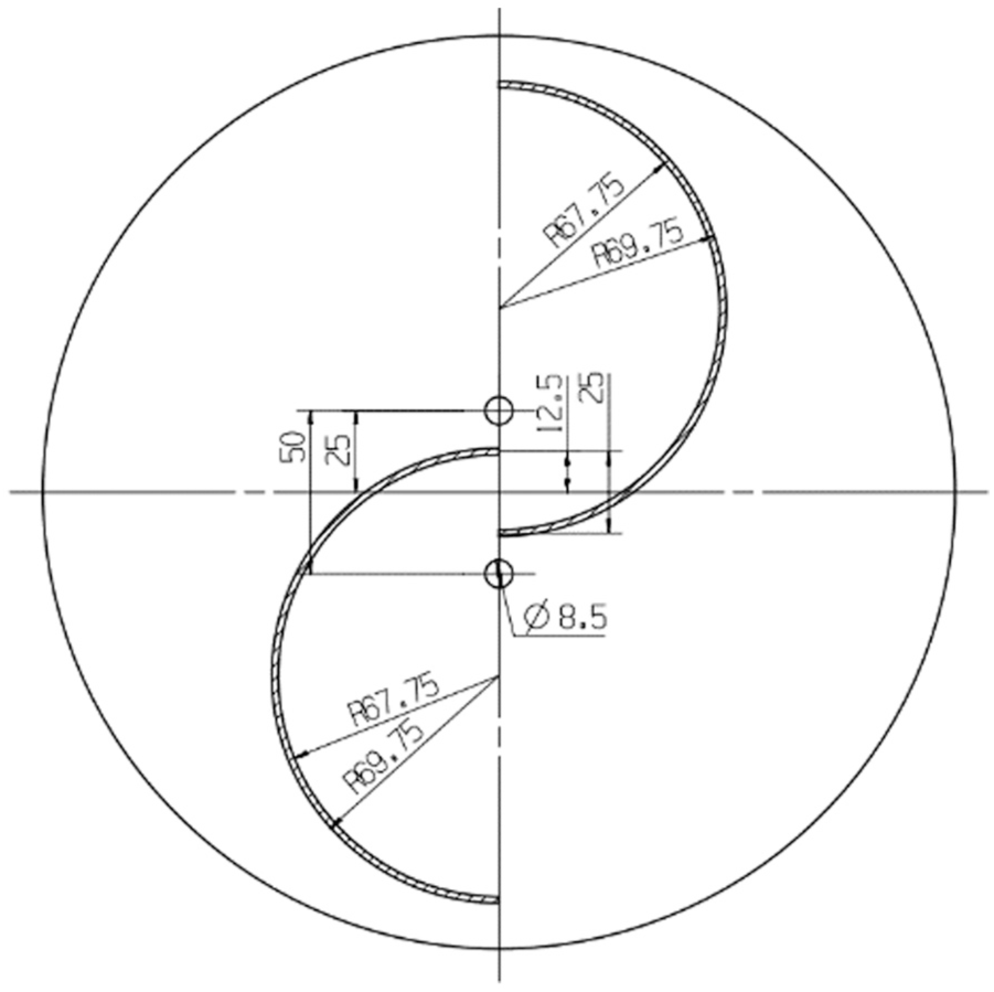
The model is scaled due to the limitations of the experimental platform. The specific dimensions of the experimental device are marked in Figure 6. In the figure,
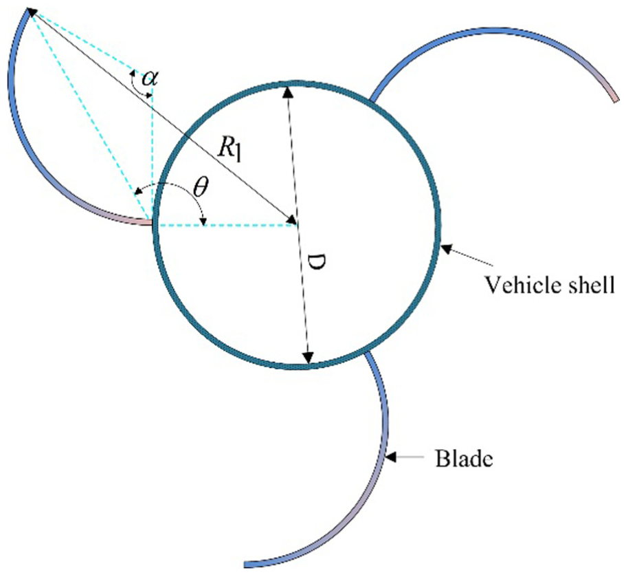
The specific dimensions of the experimental device.
In order to examine the performance of experimental devices, a small towing tank was designed. The towing tank includes a sink, motor A, motor B, a conveyor belt, a parallel rail, a stopper, and an experimental test section. Motor A drives the experimental device moving horizontally through a conveyor belt, in order to imitate the circumstance of seabed currents. Motor B drives the vertical shaft to control the angular velocity of the impeller. Figure 7 shows the physical figure of the towing tank. The specific parameters are shown in Table 1.
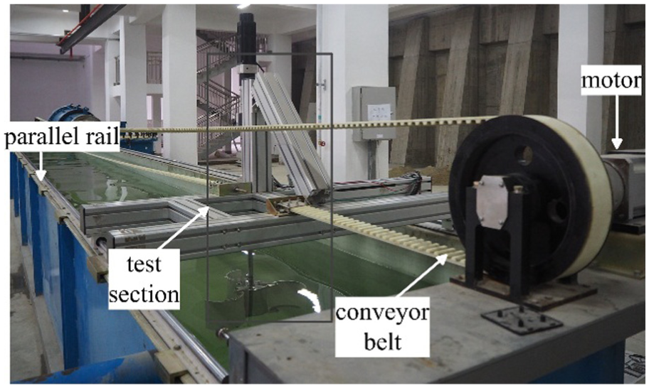
Physical figure of the towing tank.
The specific parameters of the towing tank.

The experimental test section includes an experimental device, an angular contact ball bearing, torque sensors, couplings, and the testing equipment’s control and data acquisition system. Figure 8 shows the simplified diagram of the experimental test section. The control and data acquisition system controls the speed of motor B, so as to test the difference between the different speed ratios. The couplings record the torque of a moment of gas pressure every 0.15 s and then calculate the received torque.

The simplified diagram of the experimental test section.
Experimental results of the classical Savonius rotor
Savonius rotor made out of half cylinders is a very simple concept where the whole rotor turns around a vertical axis. The schematic of the classical Savonius rotor is shown in Figure 9 and the height of the Savonius rotor is set to 0.3 m.
Schematic of the classical Savonius rotor.
Computational domain and boundary conditions
The boundary conditions are shown in Figure 10. The size of the computational domain was chosen as a rectangular domain with the size of

Computational domain and boundary conditions.
Turbulence model and mesh
Most research has shown that the
ANSYS simulated with finite volume method and discretized the computational domains. The mesh and the boundary layers are shown in Figure 11. The mesh consists of two parts: the first is fixed and the other is sliding. The sliding domain is constructed with a non-structured mesh, which ensures better adaptation to the curved geometry of the rotor. Near the blades layers of the finest volumes are used in order to improve the assessment of the boundary layer. The Re value of the blade is about

Mesh generation for the computational domain.
Setting of the solving
In this study, shear stress transport (SST) model has been used with standard surface function in the analysis of turbulent flow. Coupled solution methods were employed in calculating the pressure and velocity distributions. Standard pressure interpolation was used in spatial discretization. In order to maintain the availability of the result, second-order upwind was employed in turbulent kinetic energy and turbulent dissipation rate.
There were three rotating periods in every working condition including 360 time steps. The time step was set according to the angular velocity of the rotor so that the blades rotated
Numerical analysis
In order to avoid the effect of the size of the blade, the normalization method is applied. Here T is the brake torque,
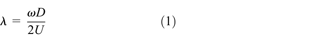
The tip speed ratio is expressed as
The torque coefficient is expressed as

The power coefficient is expressed as

Change of torque with angular velocity is measured by experiments. Then the torque coefficient and power coefficient can be calculated. Coefficients of power as a function of speed ratio are shown in Figure 12 and compared with the numerical simulation results for the classical Savonius rotor.
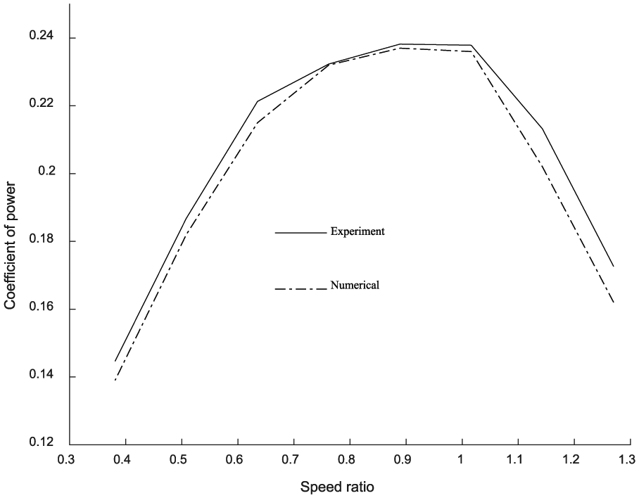
Coefficients of power as a fuction of speed ratio.
Error analysis of the experimental platform
Due to the influence of many factors, there are some errors in the measured data compared with the theoretical value. This article considers initial errors including mechanical friction and platform movement. So the initial torque is measured when the vertical axis is rotated by 0.01 rad/s, and the horizontal movement speed of the experimental test section is 0.5 m/s. The average value of the initial torque is 0.068 N m. The comparison between the experimental data of the classical Savonius blades and simulation results also verifies the existence of initial errors.
Experimental results and discussion
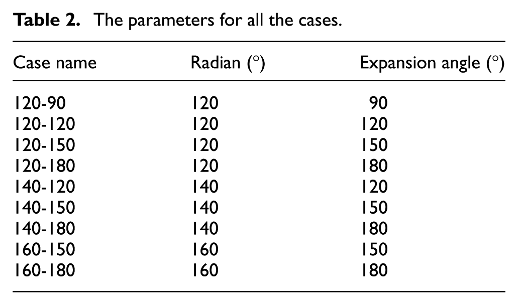
The performance of the experimental device depends on different parameters like the number of blades, the number of stages, and the geometry of the blades. There is no exact theoretical procedure to obtain the optimal solution till now. The best way of optimizing the various parameters is to carry out a number of experiments on the different parameters. Referring to the numerical simulations that have already been done, the number of blades is set to three. Considering the application background, the shape of the blade is chosen to be arc, the diameter of which is equal to the vehicle shell’s diameter. The main consideration in this article is the radian and expansion angle of the blade. All the test cases are presented in Table 2.
The parameters for all the cases.
Optimum expansion angle of the blade
The power of the experimental device depends on the expansion angle of the blade. The variation of power with angular velocity for the four rotors (120-90, 120-120, 120-150, 120-180) is shown in Figure 13. In this case, the radian of the blade is fixed. When the expansion angle increased from 90° to 120°, the maximum value of power increased considerably. However, when the expansion angle increased from 120° to 150°, the maximum value of power decreased because of the poor fluid performance as same as that when the expansion angle increased from 160° to 180°.

The variation of power with angular velocity for the four rotors which have the identical radians of 120 degree.
In the above experiments, the expansion angle is changed when the radian is set to 120°. Experiments have also been conducted when the radian is set to 140°. The results obtained are shown in Figure 14. The maximum value of power is recorded when the expansion angle is 150°. However, the ability to provide power when the expansion angle is set to 140° is weaker than that in the case when the expansion angle is set to 120°.

The variation of power with angular velocity for the four rotors which have the identical radians of 140 degree.
Optimum radian of the arc
In this case, the expansion angle is set to 120°. The variation of power with angular velocity is shown in Figure 15. The optimum radian of the arc is 120°. When the radian and expansion angle are both set to 120°, the upwind area increases slowly and the fluid properties are better than the others. Meanwhile, the shape has the least impact on the shape of the vehicle.

The variation of power with angular velocity for the four rotors which have the identical expansion angle of 120 degree.
Conclusion
In this article, an integrated self-generating system is designed for an AUV. The plan is valid and feasible by experiments. AUV’s endurance will be enhanced greatly. A wider range of ocean detections will be possible.
The main consideration in this article for the optimized design of an impeller is the radian and expansion angle of the blade. The radian mainly influences the geometry of the blade and shows different fluid properties. The expansion angle mainly influences the upwind area and captures energy capacity.
Taking into account the impact of the above two factors, the three optimal configurations are compared. When the radian and expansion angle are both set to 120°, the upwind area increases slowly and the fluid properties are better than the others. Hence, when the radian is 120° and the expansion angle is also 120°, the maximum power of 0.599 W can be provided. Meanwhile, the shape of the underwater vehicle is almost unaffected. Due to the integrated design, the design space is greatly reducing. As long as adding a section of extra cabin, engineering difficulty becomes easy.
Footnotes
Handling Editor: Assunta Andreozzi
Declaration of conflicting interests
The author(s) declared no potential conflicts of interest with respect to the research, authorship, and/or publication of this article.
Funding
The author(s) received no financial support for the research, authorship, and/or publication of this article.