
Abstract
Based on the magnetic field modulation effect, this article presents a magnetic gear with intersecting axes and straight stationary pole-pieces. Except for a higher utilization of permanent magnets and a greater output torque, the magnetic gear with intersecting axes and straight stationary pole-pieces provides several advantages, such as a smaller volume, higher torque density, and lower processing cost. The magnetic gear with intersecting axes and straight stationary pole-piece topology is herein introduced and the deduced constraints of the structural design are outlined. The transmission mechanism is demonstrated by analyzing the output torque in the middle of the air gaps. The effects of the main design parameters on the maximum static torque are evaluated using the finite element method. Based on the orthogonal experimental design and the response surface method, the optimum design results are provided. Prototype of the magnetic gear with intersecting axes and straight stationary pole-pieces has been realized and the static torque has been verified experimentally.
Introduction
Magnetic bevel gears (MBGs) have several advantages, such as no contact, no wear, no lubrication, low vibration and noise, and overload protection. 1 Consequently, they have received considerable attention since the 1980s as an alternative to mechanical bevel gears. However, they have few pairs of teeth to engage in the meshing on account of their adoption of the mechanical bevel gear topology. Therefore, the utilization of the permanent magnets (PMs) remains low. Moreover, the output torque and torque density are lower. 2 Especially, the larger the transmission ratio is, the lower the PM utilization is. Use of MBGs has thus been notably limited in the industry.
Transcending the parallel shaft topology of the traditional magnetic gears, the field modulated magnetic gear (FMMG) proposed by Atallah and Howe 3 adopts the coaxial topology and has a high utilization of PMs. FMMG can provide a larger torque and a higher torque density, and it can thus be widely used in the vehicles, wind turbine systems, navigation, and other fields.4–6 More than a decade ago, FMMG began attracting the attention of scholars, and many studies have been carried out. Novel types of the magnetic gears have been proposed, such as the high-performance linear magnetic gear and axial-field magnetic gear.7,8 Meanwhile, many types of the direct current and alternating current PM motors were proposed for the wide uses. 9 But, almost all studies for the mechanisms have focused on the coaxial structures. A magnetic gear with intersecting axes (MGIA) only was presented and studied by Liu et al. 10 based on FMMG. MGIA overcomes the limitations of MBGs and has many obvious advantages, including a greater output torque and greater torque density compared with MBGs. By changing the shape of the stationary pole-pieces (SP), the intersection angle between the input and output shafts can be changed. However, because of the SP in the MGIA is a siphon and the corresponding permeable magnetic strips are some space strips with a certain helix angle. So, the SP in the MGIA is difficult to machine, and MGIA has a high machining cost.
In this article, a magnetic gear with intersecting axes and straight stationary pole-pieces (MGIASSP) is proposed. Because of the straight SP, the corresponding permeable magnetic strips are linear structure and easy to machine. So, MGIASSP has a smaller volume compared with MGIA. By changing the intersection angle between the two end-faces, the input and output shaft axes can intersect at any angle. Furthermore, the transmission ratio can be changed by changing the numbers of the pole pairs of the PMs on the input and output rotors. The MGIASSP operating principle is herein introduced and the parameter design constraints are given. By the finite element method (FEM), the effects of the main parameters on the output torque are discussed and the optimum design parameters are obtained. Prototype of the MGIASSP has been realized and the static torque test has been completed in order to verify the optimization results.
Transmission mechanism
MGIASSP is shown in Figure 1. It is composed of the input and output rotors and the SP. The input and output rotors are similar to the rotors in the axial-field magnetic gear. PMs with N1, N2 blocks, N poles, and S poles are layered at regular intervals on the end-faces of the input and output rotors, respectively. The SP with the elliptical section is composed of the non-permeable and permeable magnetic strips layered at different intervals. The number of the permeable and non-permeable magnetic strips is N1 + N2. A certain angle exists between the two end-faces of the SP; it is usually 90 degrees. The two end-faces of the SP are circular rings, and they are opposite to the PMs on the input and output rotors. In the peripheral direction, the silicon steel sheets with the equal length are laminated into the permeable magnetic strips with the different cross sections. But at the marginal parts of each permeable magnetic strip, the cross sections of the silicon steel sheets are different in order to ensure the specific cross-section shape.
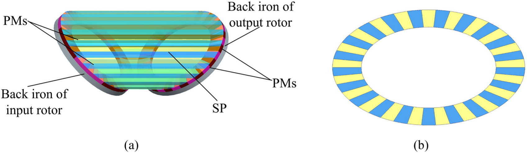
(a) Topology of the MGIASSP topology and (b) section of the SP.
Constraints
The structure diagram of the SP is shown in Figure 2(a). The intersection angle between the input and output rotors is α + β. Here, α and β are the angles between the end-faces and the plane perpendicular to the SP axis, respectively. Usually, α = β, especially α = β = 45°, when the input axis is perpendicular to the output axis.

Structure constraints of the SP: (a) schematic diagram, (b) H-H radial section, and (c) end-face.
As shown in Figure 2(b), the semi-major axis and semi-minor axis of the outer ellipsoid in the radial section are a1 and b1, respectively. The semi-major axis and semi-minor axis of the inner ellipsoid in the radial section are a and b, respectively. As depicted in Figure 2(c), the two end-faces of the SP are the circular rings, and the inner and outer diameters are a and a1, respectively.
For the inner and outer rings, following expressions can be obtained in the triangles ABC and DEF

If equation (1) is met for the intersection angle and the elliptical parameters, the two end-faces can be the circular rings. In other words, the elliptical parameters in the radial section of the SP must be changed when the intersection angle between the input and output rotors changes.
Unlike the FMMG, the permeable and non-permeable magnetic strips of the SP are layered at different intervals in the radial section. However, the permeable and non-permeable magnetic strips are layered at regular intervals in the end-faces. For example, take N1 + N2 = 21. When α = β = 45°, a quarter of the end-face and a quarter of the radial section are shown in Figure 2(b) and (c), respectively. Here, the assembly positions were marked with Arabic numerals, 1–10. The angles between a certain point and the horizontal axis are given in Table 1.
Assembly angle parameter in the end-face and axial section.

Static torque
A three-dimensional finite element model (TFEM) of the MGIASSP shown in Table 2 is found. In this study, the back irons of the input and output rotors are composed of the silicon steel sheet, 23TW250, and it has the lower eddy loss. The permeable and non-permeable magnetic materials of the SP consist of 23TW250 and the titanium alloy, respectively. The material characteristics of the titanium alloy are basically similar to the air, but it is good conductors of heat. Material of the PMs on the inner and outer rotors is NdFeB, and the remanence and coercivity of the PMs are presented in Table 2. NdFeB for the PMs has strong magnetic properties and can transfer the larger magnetic forces. The grid divisions of the model are manually set. The calculation can be accelerated by controlling the grid refinement. The initial grid model is presented in Figure 3. Considering that the silicon steel sheet and the air gaps are thin enough compared with the length of the SP, the diameters of the rotors and the back irons, the meshes of the air gaps and the silicon steel sheets are denser. The flux density vector distribution can be computed and is shown in Figure 4.
Parameters of the sample MGIASSP system.
MGIASSP: magnetic gear with intersecting axes and straight stationary pole-pieces; SP: stationary pole-pieces; PMs: permanent magnets.

TFEM of the MGIASSP.
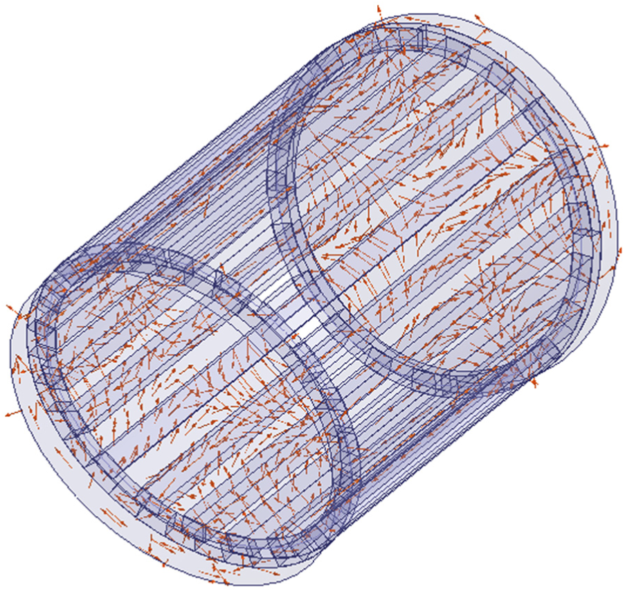
Flux density vector distribution of the MGIASSP.
In Figure 4, it is shown that the flux density vectors in the back irons of the input and output rotors close near the contact regions of the adjacent PMs. Most of the flux density vectors close and form circuits through the input rotor, output rotor, and SP. These indicate that the magnetic gear drive can be realized by the magnetic field coupling. The torque and movement will be transmitted.
Because of the magnetic field modulating of the SP, there are multiple harmonic components in the two magnetic fields of the air gaps. 11 The flux density space harmonics can be given by

j = 1, 2; m = 1, 3, 5, …; k = 0, ±1, ±2….
The main harmonics of the magnetic fields are the numbers of pole pairs of the PMs, 4 and 17, respectively. The relative amplitudes of the other space harmonics are much smaller and do nothing to output torques. 12 When the output rotor is fixed and the input rotor is running at a certain speed, the static torque can be obtained and is shown in Figure 5. Here, θ is the relative rotation angle of the input rotor around its axis. Only the main harmonics contribute to the output torques and are shown in Figure 5(b) by Maxwell’s stress tensor method and FEM. 13 But the other space harmonics will result in the eddy current loss.

Static torque and harmonics of the magnetic torque in the middle air gaps. (a) Static torque; (b) harmonics contributing to the static torques.
Similar to FMMG, the static torques roughly vary with the sine wave as the relative rotation angle increases. The period is related to the number of pole pairs of the PMs on the input rotor N1, T1 = 2π/N1. The torque ratio is equal to the transmission ratio of the MGIASSP system, i = N2/N1.
Influence of design parameters on the static torque
The two main evaluation indicators of the MGIASSP transmission performance are the maximum static torque and the torque density. The design parameters have significant effects on the static torque of the MGIASSP system. An effect analysis assists in selecting the best design parameters and improving the material utilization and torque density.
The volume of the MGIASSP system is shown in Figure 6. It can be approximately calculated as


Volume of the MGIASSP system.
The change curves of the maximum static torque on the output rotor can be calculated by the finite element simulation. Based on equation (3), the corresponding torque density curves can also be obtained by the FEM.
When the influence of the design parameters on the static magnetic torque and the torque density is analyzed, very few parameters will change, and other parameters will be invariant. The influence parameters are (1) the axial thicknesses of the PMs on the input and output rotors are equal and synchronously change. (2) The radial thicknesses of the PMs on the input, output rotors, and the SP are equal and synchronously change. (3) The two air gap thicknesses are equal and synchronously change. (4) The axial thicknesses of the back irons of the input and output rotors are equal and synchronously change. (5) The minimum axial length of the SP changes. The change curves of the maximum static torque on the output rotor and corresponding torque density to the main design parameters are shown in Figure 7.

Maximum static torque and torque density with the increase in the axial thickness of the PMs. (a) Axial thicknesses of the PMs, (b) radial thicknesses of the PMs, (c) air gap thicknesses, (d) axial thicknesses of the back irons, and (e) minimum axial lengths of the SP.
Figure 7(a) shows that the maximum static torque first increases and then stabilizes with the increase in axial thickness of the PMs hm. When hm is smaller and increases, the magnetic flux density increases, and the static torque will rapidly increase. When hm is more than 18 mm and continues to increase, the increasing magnetostatic energy will gradually balance with the magnetic resistance loss, and the static torque will tend to a stable constant.
When hm is smaller and increases, the static torque quickly increases and the volume increase is relatively slow. Thus, the torque density will increase as well. When hm is more than 13 mm and continues to increase, the increase of the static torque slows, and the volume increase is relatively fast. Then, the torque density will decrease. That is, the torque density of the MGIASSP system will increase first and then decrease with the increase of hm.
Figure 7(b) indicates that, with an increase in the radial thicknesses of the PMs hr, the maximum static torque will invariably increase and then decrease. When hr is smaller and increasing, the coupling areas increase and the maximum static torque will invariably increase. When hr is more than 60 mm and continues to increase, the coupling areas increase so slowly, and the magnetic resistance and magnetic loss of the SP will be larger. So, the maximum static torque will decrease gradually. Because the assembly volume of the MGIASSP system remains unchanged with the increasing of hr, the torque density of the MGIASSP system will increase and then decrease.
Figure 7(c) illustrates that the maximum static torque will decrease with the increase in air gaps thicknesses of ha. Because of the low air permeability, the magnetic resistance and the magnetic potential loss increase with the increasing of ha. The static torque will also gradually decrease. Meanwhile, the assembly volume of the MGIASSP system will increase very slowly. Thus, the torque density will decrease with an increase in ha.
To improve the output torque, the air gaps must thin out. Considering the mechanical assembling and the strong magnetism of the PMs, the air gap thicknesses should be in the range of 0.5–1 mm.
Figure 7(d) suggests that the maximum static torque will increase quickly and then tend to be a constant with an increase in the thicknesses of the back irons, hb. When hm is fixed, and hb is too thin and increases, magnetic saturation occurs and the magnetic resistances are larger; moreover, the output torque of the MGIASSP system is limited. The thicker the back iron is, the more permeable is. With hb increasing, the magnetic saturation will be relieved and gradually vanish. When hb is more than 12 mm, the output torque will reach a stable value.
When the thickness of the back irons hb is thin and increase, the maximum static torque increases quickly and the volume of the MGIASSP system increases relatively slowly. In addition, the torque density will gradually increase. When hb is more than 8 mm, the increase in assembly volume exceeds the maximum static torque and the torque density will gradually decrease.
Figure 7(e) shows that the maximum static torque decreases with the increase in the minimum axial length of the SP lf. Because of the special construction of the SP, the length of the SP is larger and the magnetic field modulation is effective. With lf increasing, the magnetic resistance, magnetic loss, and assembly volume quickly increase, and the static torque and torque density will decrease.
Optimization
Establishment of sample points
Based on the effects of the design parameters on the maximum static torque and torque density, more effective parameters can be obtained and are shown in Table 3. Here, ha and lf are constants considering the structural design and assembly accuracy.
Effective parameters of the MGIASSP system.

MGIASSP: magnetic gear with intersecting axes and straight stationary pole-pieces; PMs: permanent magnets.
The orthogonal experimental design is adopted to obtain the optimize sample data of the MGIASSP system. In order to get a sufficient number of samples and improve the accuracy of the model prediction, four levels are set for three factors, hr, hm, and hb. The orthogonal factor level table is shown in Table 4.
Orthogonal factor level table.

Following the principle of fewer trials, the orthogonal table L16(45) can meet the experimental requirements, and the 16 groups of the experiment scheme are shown in Table 5.
Orthogonal test scheme and result of the MGIASSP system.

MGIASSP: magnetic gear with intersecting axes and straight stationary pole-pieces.
The design of the MGIASSP system can be improved with hr, hm, and hb as the design variables, and the maximum static torque and torque density as the design targets. The orthogonal test scheme and numerical results by the FEM are shown in Table 5.
Parameters optimization
Based on the experimental sample data of the orthogonal test and the simulation results, the response surface method is used to optimize the parameters of the MGIASSP system. By the parameter optimization software, the response surface approximation model between the optimization parameters and optimal targets can be established. So, the optimal model for multi-parameter optimization design will be obtained. 14
The response surface model can be fitted by the high-order polynomial. Considering the few variables, the cubic polynomial can meet the fitting precision. Based on the sample data and results in Table 5, the response surface approximation models can be obtained as follows


where
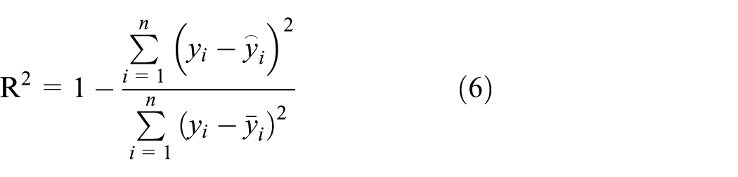
In the response surface method, the agreement of the approximate model with the experimental samples usually is measured by the multiple correlation coefficient R2. R2 can be given as follows
where n is the number of samples;
R2 is generally greater than 0.9 to ensure a high degree of credibility. According to the error analysis, R2 of the maximum static torque and torque density are 0.998 and 0.992, and are all bigger than 0.9. So, the fitting precision of the approximate model is better.
The parameter optimization design of the MGIASSP system with the multi-parameter and multi-objective can be realized by the non-dominated sorting genetic algorithm-II. Optimal object can be given
During the optimization process, the population size, hereditary algebra and crossover probability are set to 60, 30, and 0.9, respectively. The crossover distribution index and mutation distribution index are 10 and 20, respectively. After the 1560 step iteration, the values of the maximum static torque and torque density in every generation are can be calculated. Partial calculation data are shown in Table 6.
Partial calculation data of the MGIASSP system.

MGIASSP: magnetic gear with intersecting axes and straight stationary pole-pieces.
In the process of the optimization, the feasible solution, non-feasible solution, and optimal solution can be judged by the optimization software. In the partial calculation data shown in Table 6, the feasible solutions are Nos 1, 5, and 6. The optimal solution is No. 7. From Table 6, the optimal value of the maximum static torque and torque density can be obtained and are 83.906 N m and 25.30 kN m/m3, respectively. At this moment,
Verification by the FEM and torque experiment
Based on the optimized results, the thicknesses of three parts are rounded to 58, 11, and 15. The static torque of the MGIASSP system with the optimal parameters can be obtained by the FEM and is shown in Figure 8. Then, torque test of the MGIASSP prototype with the optimal parameters has been executed and shown in Figure 9. The test torques are shown in Figure 8.

Static torque on the output stator. (a) Static torque; (b) dynamic torque.

Torque test of the example prototype of the MGIASSP prototype.
Figure 8 shows that the maximum static torque of the MGIASSP system is 83.29 N m by FEM. Torque density can be calculated and is 25.206 kN m/m3 when the optimal values of the design parameters are met. These are consistent with the optimization results. The feasibility of the optimization method is verified. Meanwhile, the torque by the prototype test is slightly smaller than the torque by FEM considering the friction, the loss, the assembly error, and so on. The torque ripples of the MGIASSP system are very apparent, especially the input rotor. The torque ripples are caused by the cogging torque, and the main frequency components are the lowest common multiple between N1 and (N1 + N2), N2 and (N1 + N2), and these are consistent with the FMMG system. 15
The maximum static torque of the MGIASSP is improved greatly after the parameter optimization. On the basis of the input rotor, the torque density is 5.9308 kN m/m3. In Liu et al., 10 the diameter and other radial parameters are same with the example in the references, but the numbers of pole pairs of the PMs on the input and output rotors are 4 and 17, respectively. Remanence of the PMs is 1.3 T. The torque density of the total assembly is 4.68 kN m/m3. So, transmission capacity of the MGIASSP system is comparable to the MGIA system. At the same time, the processing cost of the SP is lower than the siphon SP in MGIA. It is therefore more advantageous for application to the industrialization process of the MGIASSP system.
Conclusion
The intersection angle between the input and output rotors can be changed by adjusting the radial section parameters of the SP. The elliptical parameters in the radial section must be a certain linear ratio in order that the two end-faces are the circular rings. The static torque is affected by the axial thickness of the PMs, axial thickness of the back irons, and radial thickness of the PMs. After optimization, the MGIASSP system has a higher output torque and torque density. The torque ripples of the MGIASSP system are very apparent and this will be one of the key studies.
Footnotes
Handling Editor: Jan Torgersen
Declaration of conflicting interests
The author(s) declared no potential conflicts of interest with respect to the research, authorship, and/or publication of this article.
Funding
The author(s) disclosed receipt of the following financial support for the research, authorship, and/or publication of this article: This work was supported by the National Natural Science Foundation of China (grant no. 51675463) and the Natural Science Foundation of Hebei Province of China (E2017203098).