
Abstract
This article proposes a new magnetic rear hub transmission for bicycles, which consists of a coaxial magnetic gear mechanism to serve as the speed-changing device and a speed control mechanism to govern the gear stage. A 3-speed magnetic hub transmission, including a low-speed gear, a direct-drive gear, and a high-speed gear, is designed and installed in the rear hub of a bicycle, which allows the rider to select different gears to adjust the pedaling force. For a new kind of rear hub transmission, kinematic analysis and power-flow path analysis are essential to validate the speed ratio and the power-flow path at each gear stage. They are also the fundamentals for the mechanical efficiency analysis. Here, a system’s kinematic equation, which is an analytical approach and analogous to the kinematics of a basic planetary gear train, for the presented coaxial magnetic gear mechanism is derived without considering the complex space harmonics of the magnetic flux density distribution presented in previous studies. Hence, the speed ratio at each gear stage of the magnetic hub transmission can be easily calculated.
Introduction
A bicycle is a human-powered vehicle applied to solo transportation and recreation. Typically, the transmission systems of bicycles are classified as two main devices: the external chain derailleur and the internal gear hub transmission.1,2 The classical external chain derailleur moves a chain between rear sprockets with different numbers of teeth by way of a chain shifting mechanism to change the driving torque and speed. The internal gear hub transmission uses an epicyclic gear mechanism sealed within the hub as a speed-changing device to generate several gear ratios. Typically, the internal gear hub transmission is more compact and more reliable than the exterior chain derailleur. It is also durable and requires much less maintenance. Besides, the internal gear hub transmission overcomes the shortcoming of gear jumping, which frequently occurs in the external chain derailleur system. The main body of an internal gear hub transmission is a set of gear mechanisms, especially a set of epicyclic gear mechanisms. 3 For the existing products4–6 and current designs,7–9 all of the gear elements used for internal gear hub transmissions are traditional mechanical gears with involute gear teeth. The torque and power are transmitted from the rear sprocket to the rear wheel through meshed gear teeth and mechanical clutches.
Although the meshed involute gear teeth possess an exact velocity ratio, the principle drawbacks are friction, wear, impact, and noticeable noise. 10 These are due to the direct contact of gear tooth profiles, resulting in undesirable energy consumption, vibration, and heat. To overcome the above inherent defects, an interesting idea of a non-contact magnetic gear with permanent magnets was first proposed by Faus. 11 Yao et al. 12 presented a biaxial type of magnetic gear set which is similar to a set of external-meshed ordinary gear train with parallel axes. Huang et al. 13 developed a magnetic planetary gearbox consisting of a magnetic sun gear, a carrier, a magnetic ring gear, and three magnetic planet gears. The topological structure of this magnetic gearbox is identical to that of a conventional 5-link, two-degree-of-freedom (DOF) epicyclic gear train. After investigating the above magnetic gear mechanisms, it was found that not all of the permanent magnets on the driving and driven shafts were simultaneously coupled and applied to generate transmitted torque, which resulted in poor torque densities and limited their industrial applications. Atallah and Howe 14 proposed a coaxial magnetic gear mechanism in which all of the permanent magnets mounted on the inner and outer rotors are simultaneously coupled, and the magnetic flux densities within the inner and outer air-gaps are dramatically increased, so as to enhance the transmitted torque. Since then, the coaxial magnetic gear mechanism has received significant attention. Some relevant works were continued by several researchers. Rasmussen et al. 15 designed a coaxial magnetic gear mechanism in which the permanent magnets were buried in the inner rotor, and the mechanism was made as spoke-type instead of a surface-mounted-type. A flux-focusing coaxial magnetic gear mechanism, in which both the inner and outer rotors are spoke-type, is also presented. 16 Frank and Toliyat 17 studied a concentric planetary gear mechanism in which the interior permanent magnets on the inner rotor were arranged along the outer circumference of the rotor. Liu et al. 18 investigated a coaxial magnetic gear mechanism in which the permanent magnets with the same polarity were buried in the yoke of the outer rotor to improve the mechanical integrity and save the permanent magnet material, while the torque density was maintained. Although coaxial magnetic gear mechanisms possess various mechanical configurations for different industrial applications, most magnetic gear mechanisms are used as gear reducers/amplifiers with a constant gear ratio. So far, no feasible magnetic gear mechanism has been designed for the multi-speed transmission system of a bicycle. Besides, existing magnetic gear mechanisms with a single gear ratio are ill-suited for rotational speed and torque conversions, and adjusting the pedaling force for different road conditions is difficult.
In this article, a bicycle’s multi-speed hub transmission, consisting of a coaxial magnetic gear mechanism, is proposed. The mechanical configuration and features of the bicycle’s rear hub transmission are introduced. The speed ratio (SR) of the multi-speed hub transmission caused by the magnetic field modulation at each gear stage is then analyzed. The transmitted torque at each gear stage induced by the magnetostatic field of the transmission is determined by two-dimensional (2D) finite element analysis (FEA). The power-flow path and the engagement of mechanical clutches based on the clutching sequence table are also checked. A prototype is developed and the maximum static transmitted torque is measured to verify the feasibility of the proposed design.
A magnetic rear hub transmission
The proposed magnetic hub transmission is a manual transmission that consists of a magnetic gear mechanism and a mechanical speed-control mechanism installed in the rear hub of a bicycle. The operation of the magnetic gear mechanism is governed by the mechanical speed-control mechanism, whereas a thumb shifter installed on the handle bar manipulated by a cyclist is used to activate the mechanical speed-control mechanism through a shifter cable. Figure 1(a) shows a cutaway view of the proposed magnetic hub transmission. The stationary hub axle (member 0) is mounted onto the rear fork of a bicycle. Figure 1(b) and (c) presents the exploded view and sectional drawing of the magnetic hub transmission, respectively. Table 1 lists the primary mechanical parts and related materials of the proposed magnetic hub transmission. As shown in Figure 2, the magnetic gear mechanism possesses a twin air-gap and non-contact configuration. No conjugate gear teeth exist in the hub transmission. The non-contact magnetic gear mechanism is composed of three coaxial mechanical parts: a stationary inner rotor with permanent magnets (member 1), an outer rotor with permanent magnets (member 3), and an aluminum alloy carrier with ferromagnetic steel pole-pieces (member 2) used to modulate the magnetic fluxes between the inner and outer rotors. Both the inner and outer rotors are composed of a lamination of magnetic steel slices to reduce the eddy current loss. Such a coaxial magnetic gear mechanism was originally proposed by Atallah and Howe. 14 It is usually used as a gear reducer with a high-speed inner rotor, a stationary carrier, a low-speed outer rotor, and a constant gear ratio. It is a 2-DOF mechanism, and two independent inputs are needed to generate a constrained output motion. Because the inner rotor (member 1) is secured to the stationary hub axle (member 0) to create a fixed link, providing an input constraint, the other input link can be the carrier (member 2) or the outer rotor (member 3), which is controlled by the speed-control mechanism based on the gear stage. For the speed control mechanism, two pawl-and-ratchet clutches, Ci2 and Ci3, installed on the carrier (member 2) and outer rotor (member 3), respectively, are used to import the driving power from the rear sprocket (member 4). Two pawl-and-ratchet clutches, Co2 and Co3, attached to the carrier (member 2) and outer rotor (member 3), respectively, are used to export the power to the hub shell (member 5) to drive the rear wheel. The engagements of these four pawl-and-ratchet clutches, which are mechanical one-way clutches, are determined by the related position of the axially moveable sleeve (member 8) on the stationary hub axle (member 0). In order to fit engineering reality and generate reasonable gear ratios for the proposed magnetic hub transmission, the inner and outer rotors adopt 6 and 16 permanent magnet pole-pairs with alternate polarity, respectively, as shown in Figure 2. The permanent magnets on the inner and outer rotors interact with the ferromagnetic steel pole-pieces on the carrier to create space harmonics. According to Atallah and Howe’s 14 study, the number of individual ferromagnetic steel pole-pieces on the carrier should be 6 + 16 = 22. In this way, the inner and outer rotors interact via a common space harmonic. The presented magnetic hub transmission possesses three forward gears: a low-speed gear, a direct-drive gear, and a high-speed gear. The related clutching sequence table is listed in Table 2.

A magnetic rear hub transmission for bicycles: (a) cutaway view, (b) exploded view, and (c) sectional drawing.
The primary mechanical parts of the proposed magnetic rear hub transmission.


A magnetic gear mechanism with a concentric configuration.
The clutching sequence table and related speed ratio at each gear of the magnetic hub transmission.

In contrast to the existing 3-speed rear hub transmissions with mechanical planetary gear mechanisms, 2 the presented magnetic hub transmission has the following qualitative features:
The magnetic hub transmission consists of a coaxial magnetic gear mechanism; it reduces the use of planetary gears that the traditional planetary gear train should possess. Fewer components decrease production costs, improve reliability, and make the whole rear hub transmission more compact.
Due to the non-contact feature, the presented magnetic hub transmission offers the unique characteristics of low acoustic noise, low maintenance, being lubrication free, and showing tolerance of misalignment.
The inner and outer rotors are equipped with circular permanent magnets that preclude the use of complex, precise, and expensive conjugate gear tooth profiles.
Speed ratio analysis
The SR analysis of the presented magnetic gear mechanism deals with the relative motion among the inner rotor, the carrier, and the outer rotor by neglecting the inertial effects. The SR is defined as the ratio of the input shaft speed to the output shaft speed. 19 For Atallah’s design, the coaxial magnetic gear mechanism is used as a gear reducer with a constant SR where the carrier is the fixed link, the inner rotor is the input link, and the outer rotor is the output link.
Based on a spectrum analysis of the magnetic flux density in the air-gap, the SR of this magnetic gear mechanism is 20

where ω is the angular velocity, pi is the number of permanent magnet pole-pairs on the inner rotor, and nc is the number of steel pole-pieces on the carrier. It is interesting that the kinematic structure of a coaxial magnetic gear mechanism is similar to a mechanical basic planetary gear train, which is a 5-link, 2-DOF gear mechanism. From a structural point of view, the inner rotor is equivalent to the sun gear, the outer rotor is equivalent to the ring gear, and the carrier with steel pole-pieces is equivalent to the carrier. Due to the non-contact feature of the magnetic gearset, planet gears that connect the motion between the sun gear and the ring gear are no longer required for the magnetic gear set; therefore, the kinematic relationship of a coaxial magnetic gear mechanism can be equivalent to that of a mechanical basic planetary gear train. A straightforward method for the kinematic analysis of a planetary gear train is the fundamental circuit method. 21 A fundamental circuit is made up of one gear pair, consisting of two meshing gears and one carrier to maintain a constant center distance between these two gears. Because there are two gear pairs within a basic planetary gear train, two fundamental circuit equations can be obtained. By manipulating the fundamental circuit equations, one kinematic equation, which represents the angular velocities among the sun gear, the carrier, and the ring gear, can be expressed as follows

where ωs, ωc, and ωr represent the angular velocities of the sun gear, the carrier, and the ring gear, respectively. In the gear ratios rpr = zp/zr and rps = –zp/zs, zp, zr, and zs represent the numbers of gear teeth in the planet gear, the ring gear, and the sun gear, respectively. By substituting the gear ratios rpr and rps into equation (2), the fundamental circuit equation of a basic planetary gear train is simplified as

Because the inner rotor and outer rotor of the magnetic gear mechanism are equivalent to the sun gear and ring gear of the basic planetary gear train, respectively, the number of gear-teeth on the sun gear zs can be equivalent to the number of permanent magnet pole pairs on the inner rotor pi, and the number of gear-teeth on the ring gear zr can be equivalent to the number of permanent magnet pole pairs on the outer rotor po. Besides, the sum of the numbers of permanent magnet pole pairs on the inner and outer rotors is equal to the number of ferromagnetic steel pole-pieces on the carrier nc, that is, pi + po = nc. 20 By replacing zs, (zr + zs), and zr with pi, nc, and po, respectively, the kinematic relationship of the inner rotor, the carrier, and the outer rotor of the magnetic gear mechanism can be expressed as

where ωi, ωc, and ωo represent the angular velocities of the inner rotor, the carrier, and the outer rotor, respectively. Equation (4) is the system’s kinematic equation of the coaxial magnetic gear mechanism shown in Figure 2. For Atallah et al.’s 20 design, the inner rotor is the input link, the carrier is the fixed link, and the outer rotor is the output link; the SR of this gear mechanism can be determined by applying equation (4)
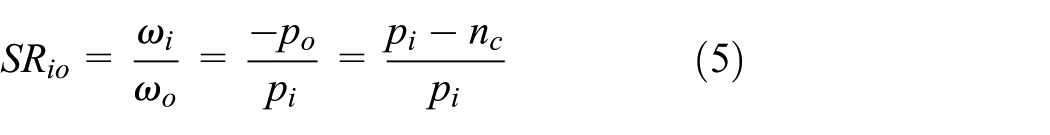
As can be seen, the SR shown in equation (5) is identical to that shown in equation (1). The system’s kinematic equation, shown in equation (4), can be applied to the kinematic analysis of the coaxial magnetic gear mechanism. The SRs of the low-speed and high-speed gears for the magnetic hub transmission are listed in Table 2.
Power-flow path analysis
The purpose of the power-flow path analysis is to examine the transmission path at each gear stage based on the clutching sequence table and to verify the feasibility of the proposed speed control mechanism. For the proposed magnetic hub transmission at the low-speed gear, the axially moveable sleeve (member 8) of the speed control mechanism is in the left position on the stationary hub axle (member 0). At this gear stage, the pawl of the clutch Ci2 on the axially moveable sleeve (member 8) is disengaged with the ratchet on the right supporting ring (member 11) of the carrier (member 2) due to axial dislocation. Meanwhile, the pawl of clutch Co3 is restrained by the flange of the axially moveable sleeve (member 8) which disengages this clutch in this state, as shown in Figure 3. Therefore, pawl-and-ratchet clutches Ci3 and Co2 are engaged simultaneously at the low-speed gear. The driving power is transmitted from the sprocket (member 4) via the pawl-and-ratchet clutch Ci3 to the outer rotor sleeve (member 6), outer rotor (member 3), carrier (member 2), pawl-and-ratchet clutch Co2 and finally, to the hub shell (member 5), as depicted in Figure 4(a). At the direct-drive gear, the axially moveable sleeve (member 8) is moved to the middle position due to the operation of the gear control bar (member 12). The pawl of the clutch Ci2 on the axially moveable sleeve (member 8) is also moved to the right position, which engages the pawl with the ratchet on the right supporting ring (member 11) of the carrier (member 2). Clutch Co3 is also in the disengagement state due to the action of the axially moveable sleeve (member 8). Hence, pawl-and-ratchet clutches Ci2 and Co2 are engaged simultaneously at the direct-drive gear. The power from the sprocket (member 4) is transmitted to the axially moveable sleeve (member 8), pawl-and-ratchet clutch Ci2, carrier (member 2), pawl-and-ratchet clutch Co2 and finally, to the hub shell (member 5), as shown in Figure 4(b). At the high-speed gear, the axially moveable sleeve (member 8) is moved to the right position on the stationary hub axle (member 0). At this gear stage, the angular velocity of the outer rotor (member 3) is greater than that of the carrier (member). For clutch Ci3, the angular velocity of the ratchet is greater than that of the pawl, which makes this clutch unengaged. In addition, the angular velocity of the pawl for clutch Co3 is greater than that for clutch Co2, putting clutch Co2 in the disengagement state. Therefore, pawl-and-ratchet clutches Ci2 and Co3 are simultaneously engaged at the high-speed gear. The power from the sprocket (member 4) is transmitted to the axially moveable sleeve (member 8), pawl-and-ratchet clutch Ci2, carrier (member 2), outer rotor (member 3), outer rotor sleeve (member 6), pawl-and-ratchet clutch Co3, and finally to the hub shell (member 5), as presented in Figure 4(c). Based on the above analyses, three forward speeds of the proposed magnetic hub transmission can be precisely achieved.
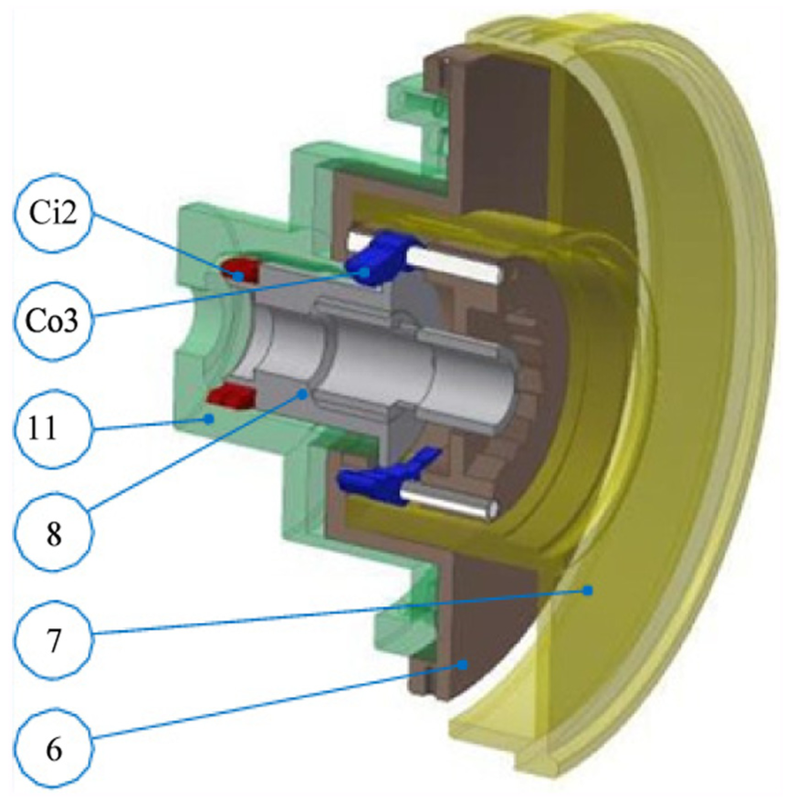
Disengagement of clutches Ci2 and Co3 at low-speed gear.

The power-flow path at each gear stage for the presented magnetic hub transmission: (a) low-speed gear, (b) direct-drive gear, and (c) high-speed gear.
FEA and experimental verification
In order to check the validity of the kinematic analysis based on the system’s kinematic equation of the coaxial magnetic gear mechanism, shown in the previous section, the 2D FEA is employed to assist in numerically estimating the angular velocity of each component. The ANSYS/Maxwell 2D field simulator is used in the magnetic field and kinematic analyses of the magnetic hub transmission. The corresponding values of the general dimension parameters and the magnet’s material parameters of the magnetic hub transmission are listed in Table 3. Figure 5 depicts the geometric parameters of the magnetic hub transmission. We set the angular velocity of the input link at 60 r/min. Figure 6(a) and (b) demonstrates the simulation results of the angular velocity analysis and transmitted torque analysis of the magnetic hub transmission at low-speed gear, respectively. At this gear stage, the outer rotor (member 3) is the input link and the carrier (member 2) is the output link, with an angular velocity of 43.1 r/min. The SR for the low-speed gear is 60/43.1 = 1.39, which is close to the analytical result 22/16 = 1.38. The average transmitted torque of the carrier (member 2) at low-speed gear is 35.5 N m. Besides, the angular velocity analysis and transmitted torque analysis of the magnetic hub transmission at the high-speed gear are shown in Figure 7(a) and (b), respectively. The carrier (member 2) is the input link and the outer rotor (member 3) is the output link with an angular velocity of 82.7 r/min at a steady state. The SR at the high-speed gear is 60/82.7 = 0.73, which is identical to the analytical result 16/22 = 0.73. The average transmitted torque of the outer rotor (member 3) for the high-speed gear is 25.8 N m.
General dimension parameters and magnet’s material parameters of a magnetic hub transmission.


Geometric parameters of the magnetic hub transmission.

(a) Angular velocity versus time curve and(b) transmitted torque waveform of the magnetic hub transmission at low-speed gear.

(a) Angular velocity versus time curve and(b) transmitted torque waveform of the magnetic hub transmission at high-speed gear.
A magnetic hub transmission, based on the geometric dimensions and magnet’s material properties, as shown in Table 3, has been assembled and prototyped, as shown in Figure 8, which will be attached to the rear wheel of a bicycle. Figure 9 shows the experimental set-up. The input link of the magnetic hub transmission, that is, the outer rotor (member 3) at the low-speed gear or the carrier (member 2) at the high-speed gear, is controlled at the constant angular velocity of 60 r/min by a brushless direct current (DC) motor. The rotational velocity of the output link for the magnetic hub transmission is measured by the tachometer (type: DT-2238A, HILA). The measured angular velocities of the carrier (member 2) at the low-speed gear and the outer rotor (member 3) at the high-speed gear are 44 and 81 r/min, respectively. The measured SRs for the low- and high-speed gears are 1.36 and 0.74, respectively, which are close to the results obtained by FEA and the derived system’s kinematic equation. As for the transmitted torque, we use the high-speed gear of the rear hub transmission as an example. The average transmitted torque of the computed result by FEA, as shown in Figure 7(b), is 25.80 N m, while the measured result of the prototype is 20.52 N m. The error is about 20.50%. The difference may occur due to the assembly’s tolerance and concentricity of the inner and outer air-gaps, the resistance of the bearings and four pawl-and-ratchet clutches, the magnetic leakage of the coaxial magnetic gear mechanism, the friction of the power transmitting parts of the gear-shifting mechanism (members 6, 8, and 12 shown in Table 1), and the real magnetic performance of NdFeB35 permanent magnets, and so on. These practical engineering situations are not taken into consideration when using FEA software to calculate the transmitted torque of the magnetic transmission.
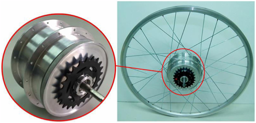
Assembled prototype of a magnetic hub transmission used for bicycles.
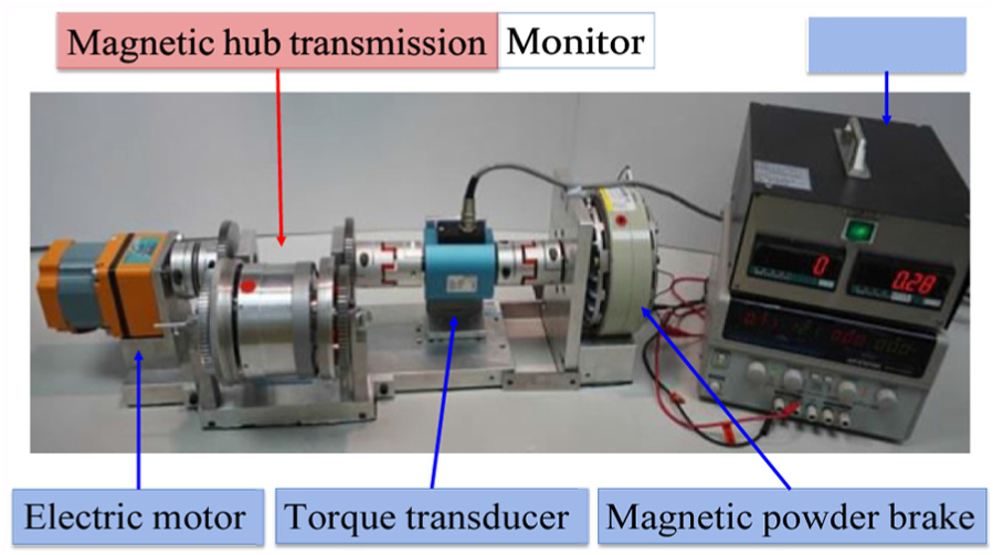
Experimental set-up for testing the proposed magnetic hub transmission.
Conclusion
In this study, a rear hub transmission with a magnetic gear mechanism for bicycles is presented. Such a magnetic hub transmission provides three forward gears: a low-speed gear, a direct-drive gear, and a high-speed gear, which allow the rider to select different gears to adjust the pedaling force. A system’s kinematic equation for the coaxial magnetic gear mechanism is derived, which is equivalent to the kinematics of a basic planetary gear train, and used to calculate the SR at each gear stage. A speed control mechanism is constructed to govern the engagement of four pawl-and-ratchet clutches. The power-flow path at each gear stage is checked and used to verify the feasibility of the proposed speed control mechanism. The SR is also confirmed by FEA and experimental testing. Although the presented magnetic hub transmission overcomes several drawbacks of conventional multi-speed hub transmissions, the ripple of the transmitted torque should be mitigated so as to improve the riding comfort. Future work related to this study will be aimed at minimizing the torque ripple by several potential approaches, including: increasing the number of magnet pole-pairs on the inner and outer rotors, skewing permanent magnets on the inner and outer rotors, or modifying the permanent magnet arc.
Footnotes
Acknowledgements
The authors are grateful to the Ministry of Science and Technology (Taiwan, R.O.C.) for supporting this research under grant no. MOST 104-2628-E-224-001-MY3 and MOST 106-2218-E-006-023. We also thank Prof. S. C. Tseng, Dean of the Office of International Affairs in the National Yunlin University of Science and Technology (Taiwan, R.O.C.), for the support of ANSYS/Maxwell software used in this research.
Handling Editor: Jan Awrejcewicz
Declaration of conflicting interests
The author(s) declared no potential conflicts of interest with respect to the research, authorship, and/or publication of this article.
Funding
The author(s) received no financial support for the research, authorship, and/or publication of this article.