
Abstract
Magnetic gear mechanisms, commonly used in specific industrial applications, possess the advantages of providing high transmission efficiency, being non-contact and maintenance free, and having overload protection. The purpose of this study is to apply a creative mechanism design methodology to come up with novel devices that combine V-belt continuously variable transmissions with coaxial magnetic gear mechanisms. The topological characteristics of the magnetic gear with an integrated continuously variable transmission are analyzed herein. The design requirements and constraints are concluded and applied to generate all feasible specialized chains. In total, 17 new design concepts featuring magnetic gear mechanisms with integrated continuously variable transmissions are obtained. The magnetostatic field of the magnetic gear mechanism is also analyzed to check the magnetic saturation and calculate the maximum transmitted torque by finite element analysis.
Introduction
In engineering applications, power can be transmitted through power transmission parts, such as gears, belts, chains, and other mechanical transmission parts. A continuously variable transmission (CVT) is a mechanical transmission with a variable output speed and a continuous speed ratio. It provides smooth and continuous variable output power to increase the convenience of mechanical operations and improve mechanical efficiency. Thus, the CVT has not only become a popular topic for engineers, experts, and scholars, but it has also been developed rapidly over the past several decades. Particularly, this study focuses on a V-belt CVT mechanism similar to that found in a scooter. An early technical paper 1 in 1955 related the various factors of an adjustable-speed V-belt drive. In Oliver and Henderson’ research, 2 kinetic equations were derived to design an automatic tensioning variable-speed V-belt drive. In Oliver and Hornung’ s study 3 a derivation of the design equations for a symmetrical V-belt drive was presented, in which the centrifugal control was governed by an expanding garter spring, and the torque control was achieved using a helical cam. Since then, many papers have researched V-belt CVTs4–9 and have made great progress.
Magnetic gears were first proposed at the beginning of the 19th century. A US Patent 1171351A 10 filed in 1916 described electromagnetic gears consisting of two rotational shafts with salient steel poles. The two shafts were magnetically connected with stationary electromagnetic poles. Another US Patent 2243555A 11 described a magnetic gear based on two disks with different diameters and a different number of permanent magnets. A coaxial magnetic gear, proposed by Atallah and Howe, 12 was the first coaxial magnetic gear mechanism that utilized all the permanent magnets to generate the transmitted torque. Since then, the torque density of a magnetic gear set has been significantly improved. Many types of concentric magnetic gears have been studied in an effort to improve the output performance.13–15
The integration of magnetic gears and CVTs possesses the unique characteristics of high efficiency, compact size, and a wide range of continuous speed ratios. However, there have been neither new design concepts nor design methodologies combining V-belt CVTs with coaxial magnetic gears based on their topologies. This study presents a creative mechanism design methodology combining coaxial magnetic gear mechanisms with V-belt CVTs.
Creative mechanism design methodology
Creative design methodology, as proposed by Yan, 16 incorporates a powerful set of procedures or design steps for systematically solving a defined problem and generating all feasible design concepts. A magnetic gear mechanism combined with two sets of V-belt CVTs is used as an example to synthesize all feasible integrated design concepts. It follows the steps given below.
Step 1: identify original designs with required design specifications
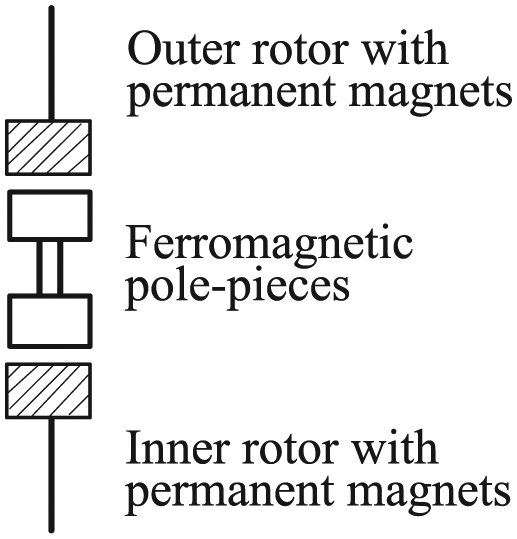
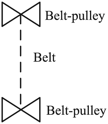
An original device of a magnetic gear with an integrated CVT consists of a CVT unit and a coaxial magnetic gear mechanism, as shown in Figure 1. This device has the kinematic property of a variable speed ratio and can be used as the power train unit for machines. The CVT unit consists of two belt-pulley sets and two V-belts, and the magnetic gear mechanism is composed of an inner rotor with permanent magnets, an outer rotor with permanent magnets, and a carrier with ferromagnetic pole-pieces. Two belt-pulleys are integrated with the inner rotor and the outer rotor of the coaxial magnetic gear mechanism, respectively. The schematic representations of a magnetic gear pair, which is a non-contact kinematic joint, and a belt-pulley joint are shown in Figure 2(a) and (b). Based on these representations, the schematic diagram of the original device is shown in Figure 3. The original device of a magnetic gear with an integrated CVT is a 7-link planar mechanism with a single input and a single output. The basic specifications regarding the topological structure of this integrated device are concluded as follows:
It is a one-degree-of-freedom (1-DOF) mechanism.
It is a planar 7-link mechanism including a frame.
The magnetic gear mechanism, with two air gaps, is a coaxial device in which all parts rotate about an identical shaft.
It has one ground link (KF, member 0) and four kinematic links (inner rotor KI, member 1; ferromagnetic pole-pieces KP, member 2; outer rotor KO, member 3; belt KB1, member 4; belt KB2, member 5; belt-pulley KBL, member 6).
It has four revolute joints (JR, joints a, b, c, and k), two magnetic gear joints (JMG, joints d and e), and four belt-pulley joints (JBR, joints f, i, g, and h).

An original device including a magnetic gear mechanism with an integrated CVT.

Schematic representations of a magnetic gear joint and a belt pulley joint: (a) a magnetic gear joint and (b) a belt-pulley joint.

The related schematic diagram of the original device.
Step 2: transform the original device into a corresponding generalized chain based on the generalization rules
An original device of a magnetic gear with an integrated CVT is further transformed into its generalized chain with only generalized links and revolute joints. The corresponding generalized chain, consisting of 7 generalized links and 10 generalized joints, is shown in Figure 4.

The generalized chain of the original integrated device.
Step 3: synthesize the atlas of generalized chains
The third step of the creative design methodology is to synthesize all possible generalized chains having the same number of links and joints as the original generalized chain. The total number of generalized chains with 7 links and 10 joints is 50. The details of the 50 generalized chains are listed in Yan’s textbook. 16 For simplicity, only eight generalized chains, as shown in Figure 5(a)–(h), are selected for specialization.

Eight generalized chains with 7 links and 10 joints: (a)-(h) part of the atlas of 7-link, 10-joint generalized chains.
Step 4: list feasible specialized chains based on the algorithm of specialization
The fourth step is to assign specific types of members and joints to each generalized chain, subject to design requirements and constraints, in order to create feasible specialized chains. The design requirements and constraints of the presented device are as follows:
There must be a ground link (KF) as the frame.
There must be an inner rotor with permanent magnets (KI), a carrier with ferromagnetic pole-pieces (KP), an outer rotor with permanent magnets (KO), and two V-belts (KB1, KB2).
The inner rotor with permanent magnets (KI), a carrier with ferromagnetic pole-pieces (KP), and an outer rotor with permanent magnets (KO) must be close to each other to form a coaxial topology.
The V-belt is only to be a binary link.
There are four revolute joints, four belt-pulley joints, and two magnetic gear joints.
Because the magnetic flux lines must pass through the ferromagnetic pole-pieces to modulate the magnetostatic field for speed reduction or multiplication, the ferromagnetic pole-pieces must be adjacent to the inner rotor and the outer rotor simultaneously.
According to the above rules, each generalized chain is further transformed into its related specialized chains. The atlas of all feasible specialized chains of the integrated device that consists of a coaxial magnetic gear mechanism and a CVT unit is created as shown in Table 1.
The atlas of all feasible specialized chains.

Step 5: particularize each feasible specialized chain
Once the feasible specialized chains are obtained, they are particularized into the corresponding mechanical devices. A functional schematic of a coaxial magnetic gear mechanism is presented in Figure 6, while the functional schematic of a V-belt CVT is depicted in Figure 7. Table 2 shows the corresponding schematics of all designs of the feasible specialized chains through particularization.
The functional schematic of a coaxial magnetic gear mechanism.
The functional schematic of a V-belt CVT.
The atlas of functional schematics of feasible specialized chains.

Step 6: new designs of magnetic gears with integrated CVTs
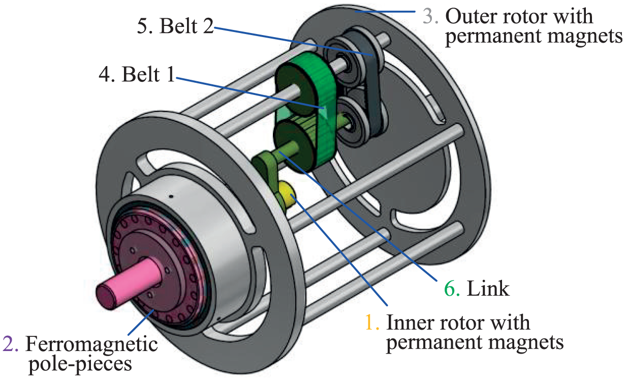
The device a-1 shown in Table 2 is the original magnetic gear with an integrated CVT. Therefore, the other 17 integrated devices, as shown in Table 2, can be claimed as new design concepts. The embodiment designs of novel design concepts e-1, f-1, g-1, and h-1 are presented in Figures 8–11, respectively.

The embodiment design of design concept e-1.

The embodiment design of design concept f-1.

The embodiment design of design concept g-1.
The embodiment design of design concept h-1.
Magnetostatic field analysis of a coaxial magnetic gear mechanism
Two-dimensional finite element analysis (FEA) is applied to investigate the magnetostatic field of the synthesized integrated device. Figure 12 shows the magnetic field distributions of a coaxial magnetic gear mechanism. The numbers of magnet pole pairs for the inner rotor, ferromagnetic pole-pieces on the carrier, and magnet pole pairs for the outer rotor are 4, 17, and 13, respectively. It can be seen from Figure 13 that the maximum transmitted torque of the coaxial magnetic gear mechanism is 17.1 N m. No magnetic saturation occurs in this mechanism. The transmitted torque and the speed ratio can be designed based on its geometric dimensions, number of permanent magnet poles, number of ferromagnetic pole-pieces, and material properties of the permanent magnets and ferromagnetic steel for yoke purposes. Due to the non-contact characteristic, it provides a unique function of overload protection when the loading is greater than the maximum transmitted torque of the coaxial magnetic gear mechanism.

The magnetic field distribution of a coaxial magnetic gear mechanism.

The transmitted torque versus time curve of a coaxial magnetic gear mechanism.
Conclusion
This study synthesizes feasible magnetic gears with integrated CVTs used for transmission systems. According to a creative mechanism design methodology, 17 novel 7-link magnetic gears with integrated CVTs are obtained. The main kinematic feature of these integrated devices is the wide range of the overall speed ratio because the two mechanical CVT sets and the coaxial magnetic gear mechanism possess the function of continuously variable transmission simultaneously. Future work on this study will involve calculating the overall speed ratio, transmitted power, and mechanical efficiency of these integrated devices for further performance evaluation.
Footnotes
Handling Editor: Jianbo Yu
Declaration of conflicting interests
The author(s) declared no potential conflicts of interest with respect to the research, authorship, and/or publication of this article.
Funding
The author(s) disclosed receipt of the following financial support for the research, authorship, and/or publication of this article: The authors are grateful to the Ministry of Science and Technology (Taiwan (ROC)) for supporting this research under Grant No. MOST 104-2628-E-224-001-MY3.