
Abstract
Flange gear has a complex geometry and its volume distribution along the axial direction changes suddenly. This makes it difficult to be formed by a single step using a simple cylinder workpiece and the preform is necessary. This research aims at proposing a preform designing approach in cold orbital forging of flange gear. A three-dimensional finite element model of cold orbital forging of flange gear is first constructed. Then, the cold orbital forging processes are simulated under different preform geometries and the insufficient filling and folding defects are studied. At last, the preform is optimized and the defects are eliminated. The experiments are also performed and the preform designing approach in cold orbital forging of flange gear is verified.
Introduction
Different from traditional upsetting, cold orbital forging has a conical top punch which has a local contacting with the workpiece. This can produce that forces used for deformation in cold orbital forging are much smaller than those in traditional upsetting. This character makes cold orbital forging exhibit significant advantage in producing complex parts with good properties.
Some studies were conducted in cold orbital forging and some study progresses were obtained. The classical cold orbital forging equipment with four paths of top punch was developed by Marciniak. 1 For revealing deforming laws, the forces used for deformation,2–4 contacting rules between workpiece and top punch,5–7 and deforming characters8–18 were analyzed with the objective of rings and cylinders. The technologies with the objective of complex parts were developed.19–27 Some new developments were obtained on new cold orbital forging technologies including rivet connection,28,29 incremental forming, 30 sheet forging,31,32 and non-rotary part forging33,34 coupled with cold orbital forging. Until now, no reports have been focused on cold orbital forging of flange gear.
Flange gear has a complex geometry and its volume distribution along the axial direction changes suddenly. This makes it difficult to be formed by a single step using a simple cylinder workpiece and the preform is necessary. This research aims at proposing a preform designing approach in cold orbital forging of flange gear. A three-dimensional (3D) finite element (FE) model of cold orbital forging of flange gear is first constructed. Then, the cold orbital forging processes are simulated under different preform geometries and the insufficient filling and folding defects are studied. At last, the preform is optimized and the defects are eliminated. The experiments are also done and the preform designing approach in cold orbital forging of flange gear is verified.
Processing routes for cold orbital forging of flange gear
The geometry of objective flange gear is shown in Figure 1. On the bottom of the flange, there are complex teeth. What is more, its volume distribution along the axial direction changes suddenly. This makes it difficult to be formed by a single step using a simple cylinder workpiece and the preform is necessary. So processing routes for cold orbital forging of flange gear are determined, as shown in Figure 2. First, the workpiece is cut from a bar. Then, the preform, which is a flange, is obtained by preform forming. At last, the final flange gear is cold orbital forged using the preform. Apparently, the most critical step is to determine the preform geometry. So this research aims at proposing a preform designing approach.

Geometry of objective flange gear.

Processing routes for cold orbital forging of flange gear.
FE modeling of cold orbital forging of flange gear
DEFORM-3D is used for simulating cold orbital forging of flange gear and the FE modeling is presented in Figure 3. Rigid bodies are assigned to the bottom punch and the top punch. The preform is deforming and meshed. A shear friction is defined between preform and punches and the friction factor is 0.15 under MoS2 lubrication. The top punch makes a circular path about its apex and the bottom punch makes a line path. The material of preform is 20CrMnTi and its mechanical parameters are from Deng et al. 22 Its constitutive model is given in equation (1). The main conditions for simulation are presented in Table 1


FE modeling of cold orbital forging of flange gear.
Main conditions for simulation.

Results and discussion
Figure 4 presents the geometry of preform which can be forged directly from a cylinder. The diameter of the slender shaft D2 of the preform is designed to be equal to that of the final flange gear. So only three parameters, namely, D1, H1, and H2, need to be determined. As shown in equation (2), as long as the two of these three parameters are determined, the left one will be determined correspondingly. Thus, the flange diameter D1 and the length of the slender shaft H2 are selected to be the designing parameters of the preform

where V is the volume of the final flange gear and is constant.

Geometry of preform.
Effects of H2 on cold orbital forging of flange gear
Figure 5 presents the effects of H2 on the geometry of the final flange gear when D1 is equal to the flange diameter of the final flange gear. It is seen that the flash of the final flange gear gradually decreases with the increase of H2. Figure 6 presents the effects of H2 on the flash size of the final flange gear, which shows similar trends as described above. It is because when H2 is smaller, the height of the flange of the preform H1 is large. In cold orbital forging, the top surface of preform first generates plastic deformations because of the smaller contacting zones between the preform and the top punch. What is more, a larger H1 can make plastic zones difficult to penetrate along the axial directions. This can make more amount of the metals on the top surface of the preform flow radially to form the flash. When H2 is larger, H1 is small. According to the description above, less metals on the top surface of the preform can flow radially to form the flash. Apparently, a larger flash size will cause the defect of insufficient filling of slender shaft of the final flange gear based on volume constancy, as illustrated in Figure 7. So one of the optimization objectives is the filling of the slender shaft. Figure 8 presents the effects of H2 on the length of slender shaft of the final flange gear. It indicates that the length of slender shaft of the final flange gear increases as H2 becomes larger. Moreover, when H2 reaches 18 mm, the length of slender shaft of the final flange gear reaches the objective value, that is, the defect of insufficient filling is avoided and the slender shaft is formed perfectly. The above results show that as long as H2 is larger than 18 mm, the slender shaft can be formed perfectly. So the range of H2 that needs to be optimized is below 18 mm.

Effects of H2 on the geometry of the final flange gear: (a) H2 = 0 mm, (b) H2 = 5 mm, (c) H2 = 10 mm, (d) H2 = 15 mm, (e) H2 = 18 mm, and (f) H2 = 21.2 mm.
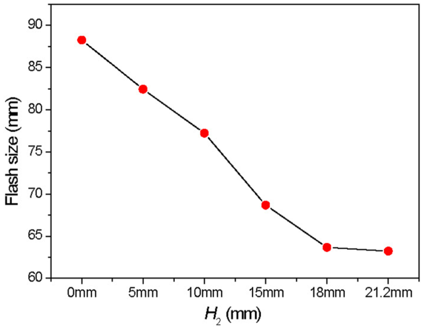
Effects of H2 on the flash size of the final flange gear.
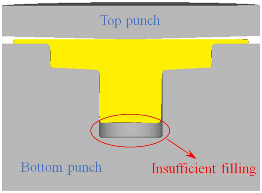
Diagram of insufficient filling of the slender shaft.

Effects of H2 on the length of slender shaft of the final flange gear.
Effects of D1 on cold orbital forging of flange gear
Figure 9 presents the effects of D1 on folding of the final flange gear when H2 is equal to the length of slender shaft of the final flange gear. It is seen that when D1 is smaller than 48 mm, folding defect forms at the lower corner of the flange (so the other optimization objective is to avoid the folding defect), as illustrated in Figure 9(a)–(d). It is because when D1 is smaller, the height of the flange of the preform H1 is larger, which can make the plastic zones difficult to penetrate along the axial directions, that is, the top zones of the flange generate larger plastic deformations for radial flow. At the bottom of the flange, the contacting area between the flange and the tooth crest of the bottom punch is smaller and so the dedendum of the flange generates larger plastic deformations for radial flow. Under such conditions, buckling occurs and folding defect forms at the lower corner of the flange. When D1 is larger (48 mm), the height of the flange of the preform H1 is smaller, which can make the plastic zones easy to penetrate along the axial directions. Therefore, the metal of the flange uniformly flows radially and folding defect can be avoided, as illustrated in Figure 9(e). The above results show that as long as D1 is larger than 48 mm, folding defect can be avoided. So the range of D1 that needs to be optimized is above 48 mm.
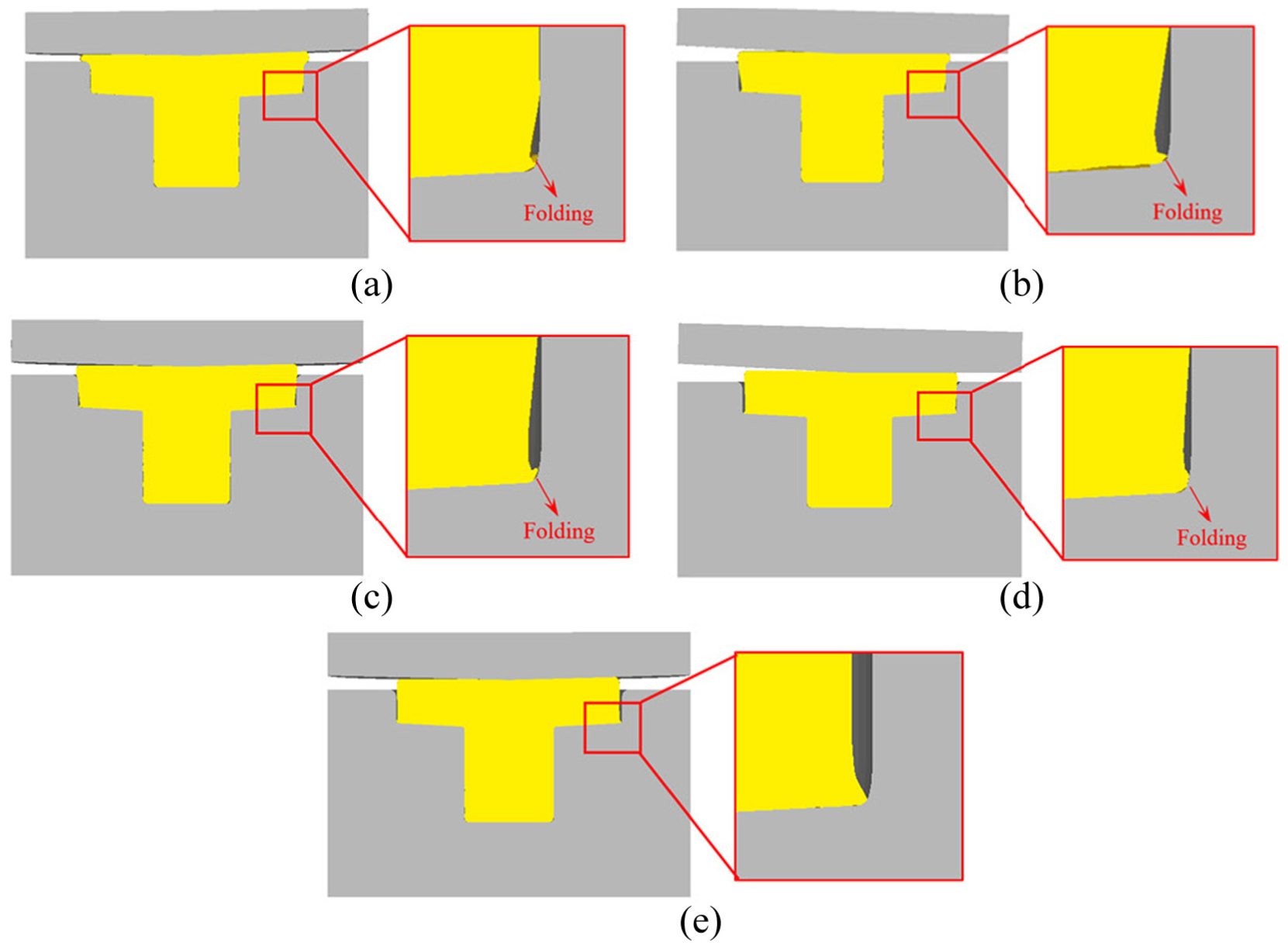
Effects of D1 on folding of the final flange gear: (a) 40 mm, (b) 42 mm, (c) 44 mm, (d) 46 mm, and (e) 48 mm.
Interactive effects of H2 and D1 on cold orbital forging of flange gear
The above results illustrate that the range of H2 that needs to be optimized is below 18 mm and the range of D1 that needs to be optimized is above 48 mm. So their interactive effects on cold orbital forging of the flange gear are revealed. Figure 10 presents the interactive effects of H2 and D1 on the formation of slender shaft of the final flange gear. From Figure 10, the ranges of H2 and D1 can be determined to guarantee sufficient filling of slender shaft of the final flange gear. Obviously, the preform with smaller H2 and D1 is much easier to be fabricated from a cylinder workpiece (when H2 and D1 are smaller, the geometric shape of the preform is closer to that of the cylinder workpiece). Thus, H2 = 17 mm and D1 = 48 mm of the preform are determined in cold orbital forging of the flange gear based on Figure 10.

Interactive effects of H2 and D1 on the formation of slender shaft of the final flange gear.
Figures 11 and 12 illustrate the deformation process in cold orbital forging of the flange gear. It is shown that the flange gear is cold orbital forged well and there are no insufficient filling and folding defects. Figure 13 illustrates the simulated punch force and the maximum punch force is 108.6 tons. The experiments are performed on a T630 cold orbital forging press which has the maximum capacity of 630 tons. Figure 14 illustrates the bottom punch used in experiments and Figure 15 illustrates the cold-orbital-forged flange gear in experiments. From Figure 15, it is seen that the flange gear is cold orbital forged well, which verifies the reasonability of the preform designing approach proposed in this research.

Deformation process of axial section in cold orbital forging of the flange gear: (a) t = 0 s, (b) t = 0.60 s, (c) t = 1.00 s, (d) t = 1.35 s, (e) t = 1.60 s, and (f) t = 1.84 s.

Deformation process of teeth in cold orbital forging of the flange gear: (a) t = 0 s, (b) t = 0.60 s, (c) t = 1.00 s, (d) t = 1.35 s, (e) t = 1.60 s, and (f) t = 1.84 s.

Simulated punch force in cold orbital forging of the flange gear.

Bottom punch in experiments.
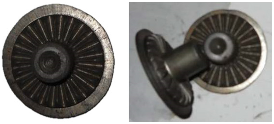
Cold-orbital-forged flange gear in experiments.
Conclusion
The formation mechanisms of insufficient filling and folding defects in cold orbital forging of flange gear are clarified.
The preform designing approach in cold orbital forging of flange gear is proposed and the defects are eliminated.
The preform designing approach in cold orbital forging of flange gear is proved by experiments.
Footnotes
Handling Editor: Jining Sun
Declaration of conflicting interests
The author(s) declared no potential conflicts of interest with respect to the research, authorship, and/or publication of this article.
Funding
The author(s) received no financial support for the research, authorship, and/or publication of this article.