
Abstract
The vibration of cold orbital forging (COF) machines is detrimental to the quality of the forged part. Therefore, it is necessary to carry out kinematics and dynamics analyses, study the vibration of the COF machine, and provide effective methods for reducing the vibration. In terms of kinematics and dynamics analyses, the mathematical modeling and model solving processes are complicated, and it takes a long time to obtain the kinetic and vibration performances of the COF machine. In this study, the kinematics and dynamics models of the COF machine were investigated. Subsequently, automatic dynamic analysis of mechanical systems (ADAMS) was applied to conduct kinematics and dynamics simulations. The simulation process was convenient and time-saving, and the simulation of the COF machine was effectively verified by conducting an experiment. Based on the simulation results, the kinetic and vibration performances of the COF machine were studied. In addition, a structure optimization method for the COF machine is proposed. Based on the singularity stability theory, the Hopf bifurcation and chaos phenomena are less likely to occur on the optimized COF machine, and therefore the vibration of the optimized COF machine is stable. Meanwhile, the structure optimization method was proven to be effective in reducing the vibration of the COF machine, which improves the quality of the forged part.
Keywords
Introduction
With the rapid development of the automobile manufacturing industry, the manufacturing requirements of automobile parts have increased. Currently, it is difficult for common forging processes to manufacture automobile parts with high efficiency, low cost, and high performance. This is owing to the large forming force, low material utilization rate, and poor forming performance of the common forging. Cold orbital forging (COF) is an advanced and complex incremental metal-forming technology. 1 In contrast to common forging, COF can reduce the forming force, improve the material utilization rate, and improve the forming performance. This enables the COF to manufacture automobile parts with high efficiency, low cost, and high performance. Consequently, COFs have been widely applied to manufacture various automobile parts. Nevertheless, during the COF process, the COF machine tends to vibrate owing to the influence of the force on the COF machine, which is detrimental to the quality of forged parts. To improve the quality of the forged parts, it is necessary to investigate the kinematics and dynamics of the COF machine and the methods of reducing the vibration.
Some studies have focused on the COF. From the COF process aspect, Samołyk2,3 and Han and Hua4,5 carried out the research on the deformation mechanism of parts in the COF process. The forging force in the COF process was studied using the upper-bound method 6 and experimental methods. 7 From the COF kinematics aspect, Han et al.8,9 revealed the kinematic mechanism and obtained kinematic equations of the COF machine. Feng et al. 10 and Dong et al. 11 demonstrated the influence of structural parameters on the kinetic locus of a COF machine. From the COF applications aspect,12–15 investigated the applications of the COF in manufacturing spur bevel gears, gear racks and rings. However, most studies on COF machines have focused on the COF process and the kinematics of the COF machine. However, few studies have been carried out on the vibration of the COF machine.
In recent years, many studies on the vibration of metal-forming machines have focused on the vibration of cold rolling, punching press and milling machines. Regarding the cold rolling machines, Liu et al. 16 and Bar and Świątoniowski 17 established a vertical dynamics model of a cold rolling machine with nonlinear external excitation. Lu et al.18,19 established a vertical dynamics model and a horizontal dynamics model, and the accuracy of the dynamics model was verified by the experimental results. Kim et al.20,21 investigated several factors affecting the vibration on the rolling machine, and the results indicated that a small rolling force, small rotation speed of the work roll and small chatter frequency contributed to reducing the vibration. Regarding the punching press machine, Liu and Li 22 studied the dynamics behavior caused by dynamic pressure on the mechanical arm of the punching press machine. Pan et al. 23 studied the dynamic characteristics of a nonlinear punching press machine with weak rigidity and negative friction velocity gradient under different working conditions. Regarding the milling machine, Ding et al. 24 presented a three-dimensional cutting force model of the two-dimensional vibration-assisted micro end milling, and established a cutting process dynamics model of the two-dimensional vibration-assisted micro end milling. Li et al. 25 built an extended dynamics model of a milling machine considering mode coupling and process damping. In comparison to those of the cold rolling, punching press, and milling machines, the kinematics mechanism and dynamics model of the COF machine are more complicated. Therefore, the dynamics models of those machines cannot be applied to a COF machine.
Based on the kinematics mechanism of the COF machine, Chen et al.26,27 established kinematics and dynamics mathematical models, and investigated the vibration performance of the COF machine. However, the mathematical modeling and model solving processes are complicated, and it therefore takes a long time to obtain the vibration performance of the COF machine. Automatic dynamic analysis of mechanical systems (ADAMS) is a practical software for the kinematics and dynamics simulations. 28 In particular, the simulation process is convenient and time-saving. 29 Therefore, it is more efficient to apply ADAMS to conduct a dynamics simulation and analyze vibration performance. However, there are few studies on applying ADAMS to conduct a dynamics simulation of a COF machine. The objective of this study is to conduct original research on the use of ADAMS and perform kinematics and dynamics simulations of the COF machine. Based on the simulation results, the kinematics and dynamics performances of the COF machine were investigated. Subsequently, a useful method of reducing vibration was proposed to improve the quality of the forged parts.
The kinematics simulation of the COF machine
The kinematics mechanism of the COF machine
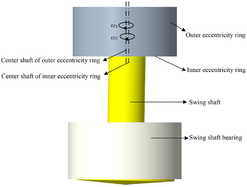
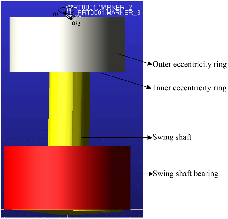
The structure of the T630 COF machine is illustrated in Figure 1. The COF machine mainly consists of four parts: a motor system, swing shaft-eccentricity ring system, cold orbital forging area of the forging part, and hydraulic system. During the COF process, the torque drives the inner eccentricity ring and the outer eccentricity ring to rotate around their respective center axis. The rotation of the outer eccentricity ring also leads to a swing in the inner eccentricity ring around the center axis of the outer eccentricity ring. Therefore, the movement of the inner eccentricity ring is the resultant of the rotation around the center axis of the inner eccentricity ring and the swing around the center axis of the outer eccentricity ring. The movement of the swing shaft is the resultant of the swing around the center axis of the inner eccentricity ring and the swing around the center axis of the outer eccentricity ring. In addition, the swing shaft contacts the forging part, and the movement of the swing shaft directly influences the forging of the part.
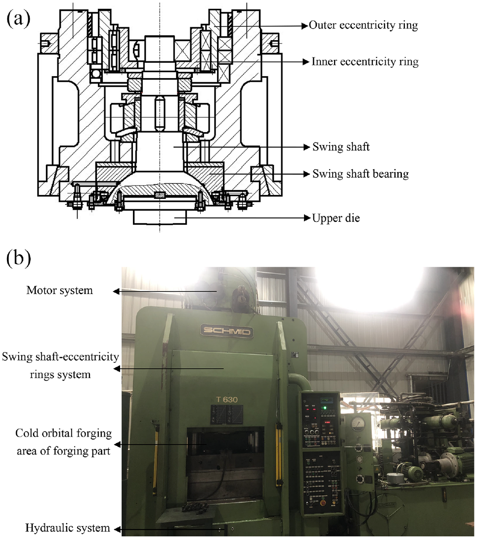
Structure (a) and equipment (b) of T630 COF machine.
The kinematics model of the COF machine
As shown in the kinematics mechanism of the COF machine, the inner eccentricity ring and outer eccentricity ring are the driving components, and the swing shaft is the driven component. The kinematics model of the swing shaft-eccentricity rings system is shown in Figure 2, where, O (x,y,z) is the peak of the swing shaft, O1 (x1,y1,z1) is the center of the outer eccentricity ring, O2 is the center of the inner eccentricity ring, and O3 is the center of the upper surface of the swing shaft. In addition, e1 is the eccentricity of the outer eccentricity ring (distance between points O1 and O2, m), and e2 is the eccentricity of the inner eccentricity ring (distance between points O2 and O3, m). The rotation of O1O2 around O1 represents the rotation of the outer eccentricity ring around its center axis, for which the angular velocity is ω1 (rad/s). The rotation and swing of O2O3 around O2 and O1 represents the rotation and swing of the inner eccentricity ring around the center axis of the inner and outer eccentricity ring respectively. The angular velocity of the rotation of O2O3 around O2 is ω2 (rad/s). The swing of O3 around O1 and O2 represent the swing of the swing shaft around the center axis of the outer and inner eccentricity rings, respectively.
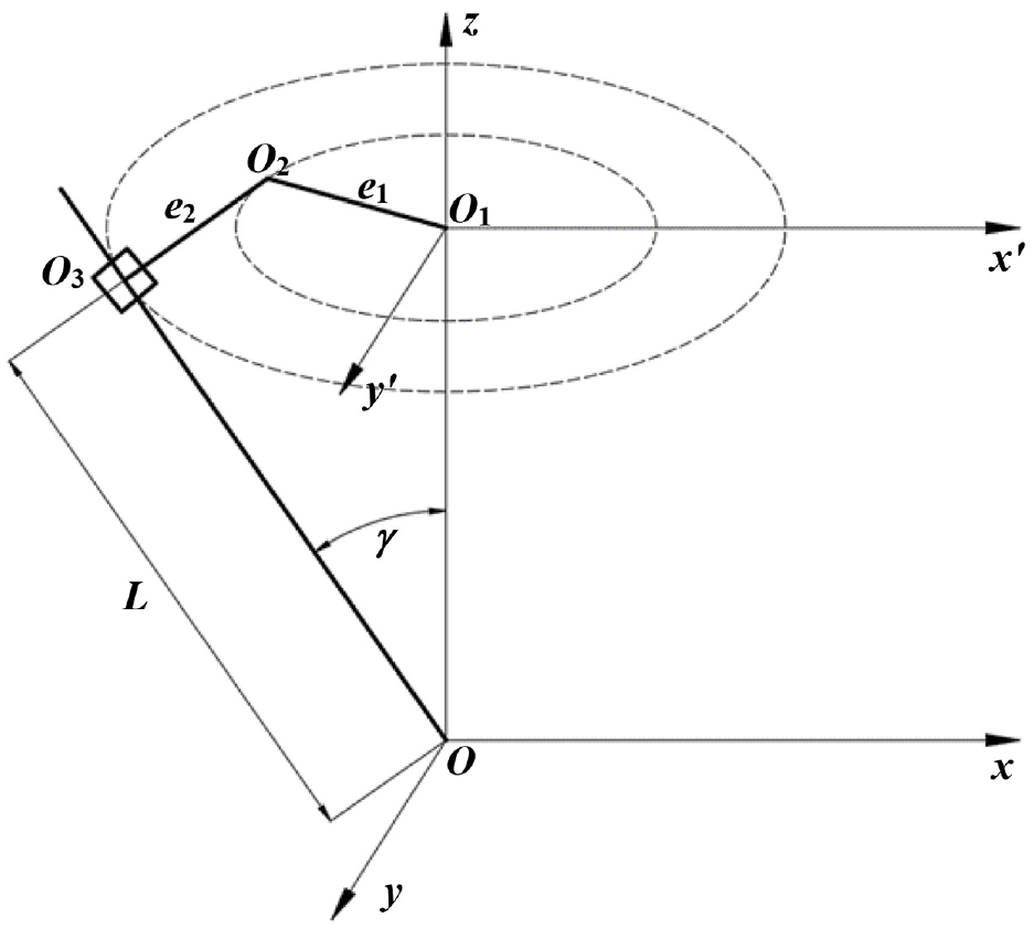
Kinematics model of swing shaft-eccentricity rings system.
Based on the kinematics model of the swing shaft-eccentricity rings system, the two-dimensional kinematics equation of point O3 can be expressed by equation (1).
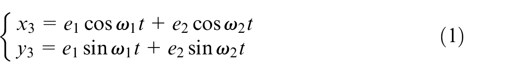
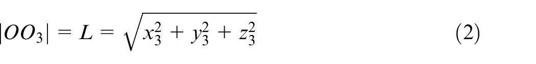
O (0,0,0) is the peak of the swing shaft and the origin of the coordinate system of the swing shaft-eccentricity rings system. The length of the swing shaft is L and can also be expressed by equation (2).
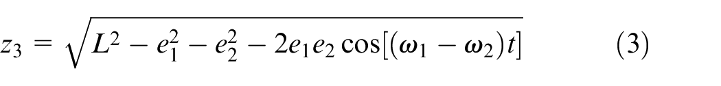
Introducing equation (1) into equation (2), equation (3) can be obtained as:
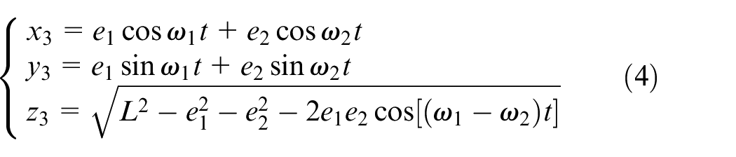
Therefore, the three-dimensional kinematics equation for point O3 can be expressed by equation (4).
Parameters of the T630 COF machine are shown in Table 1.
Parameters of T630 COF machine.
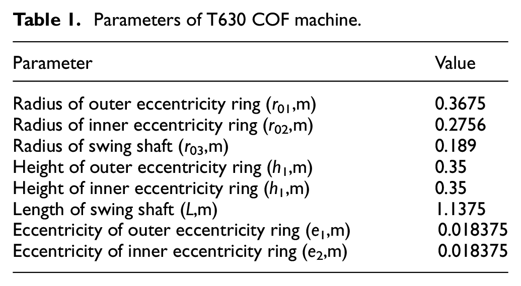
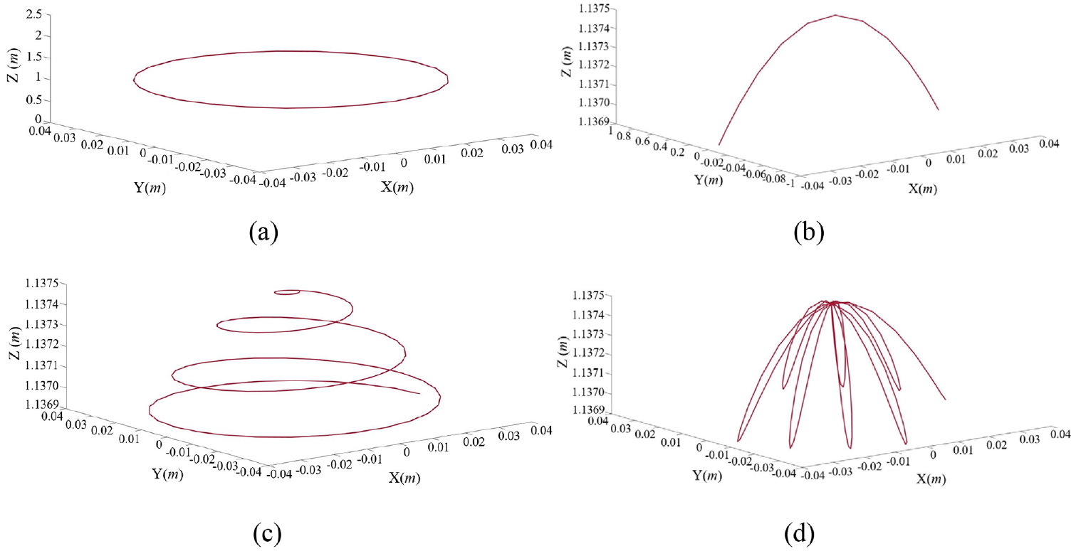
By introducing the parameters of the T630 COF machine into equation (4), the numerical solutions of the motion trail of point O3 can be obtained using MATLAB (numerical solving software), as shown in Figure 3. The magnitudes and directions of ω1 and ω2 influence the motion trail of point O3. If the magnitudes and directions of ω1 and ω2 are the same, the motion trail of point O3 will be a circle. If the magnitude is the same but the direction is different, the motion trail of point O3 will be the curve. If the magnitude is different but the direction is same, the motion trail of point O3 will be a helix. If the magnitude and direction are different, the motion trail of point O3 will be a rose curve.

Motion trail of swing shaft (a) ω1 = 8π rad/s, ω2 = 8π rad/s (b) ω1 = 8π rad/s, ω2 = −8π rad/s (c) ω1 = 8π rad/s, ω2 = 7π rad/s (d) ω1 = 8π rad/s, ω2 = −7π rad/s.
The kinematics simulation of the COF machine
As shown in Figure 4, a three-dimensional model of the swing shaft-eccentricity ring system was established in CREO (a common three-dimensional modeling software). The converting file for this model was set as the “*.X_T” file to be imported into ADAMS for the subsequent simulation. According to the kinematics mechanism of the COF machine, the motor drives the inner eccentricity ring and the outer eccentricity ring to rotate around their center axis. Therefore, during the kinematics simulation process, the revolute pair and angular velocity are applied to the inner and outer eccentricity rings. In addition, a spherical pair was applied between the swing shaft and the swing shaft bearing, and the fixed pair is applied on the swing shaft bearing. As a result of the simulation, the motion trail of point O3 was exported.
Three-dimensional model of swing shaft-eccentricity rings system.
The kinematics simulation model of the swing shaft-eccentricity rings system is shown in Figure 5.
Kinematics simulation model of swing shaft-eccentricity rings system.
The kinematics simulation results of the swing shaft-eccentricity rings system are shown in Figure 6. If the magnitudes and directions of ω1 and ω2 are the same, the simulation motion trail of point O3 will be the circle. If the magnitude is same but the direction is different, the simulation motion trail of point O3 will be a curve. If the magnitude is different but the direction is the same, the simulation motion trail of point O3 will be a helix. If the magnitude and direction are different, the simulation motion trail of point O3 will be the rose curve. The simulation motion trail of point O3 is the same as the motion trail of point O3 obtained by numerical solving.
Simulation motion trail of swing shaft: (a) ω1 = 8π rad/s, ω2 = 8π rad/s, (b) ω1 = 8π rad/s, ω2 = −8π rad/s, (c) ω1 = 8πrad/s, ω2 = 7π rad/s, and (d) ω1 = 8π rad/s, ω2 = −7π rad/s.
The dynamics simulation of the COF machine
The dynamics model of the COF machine
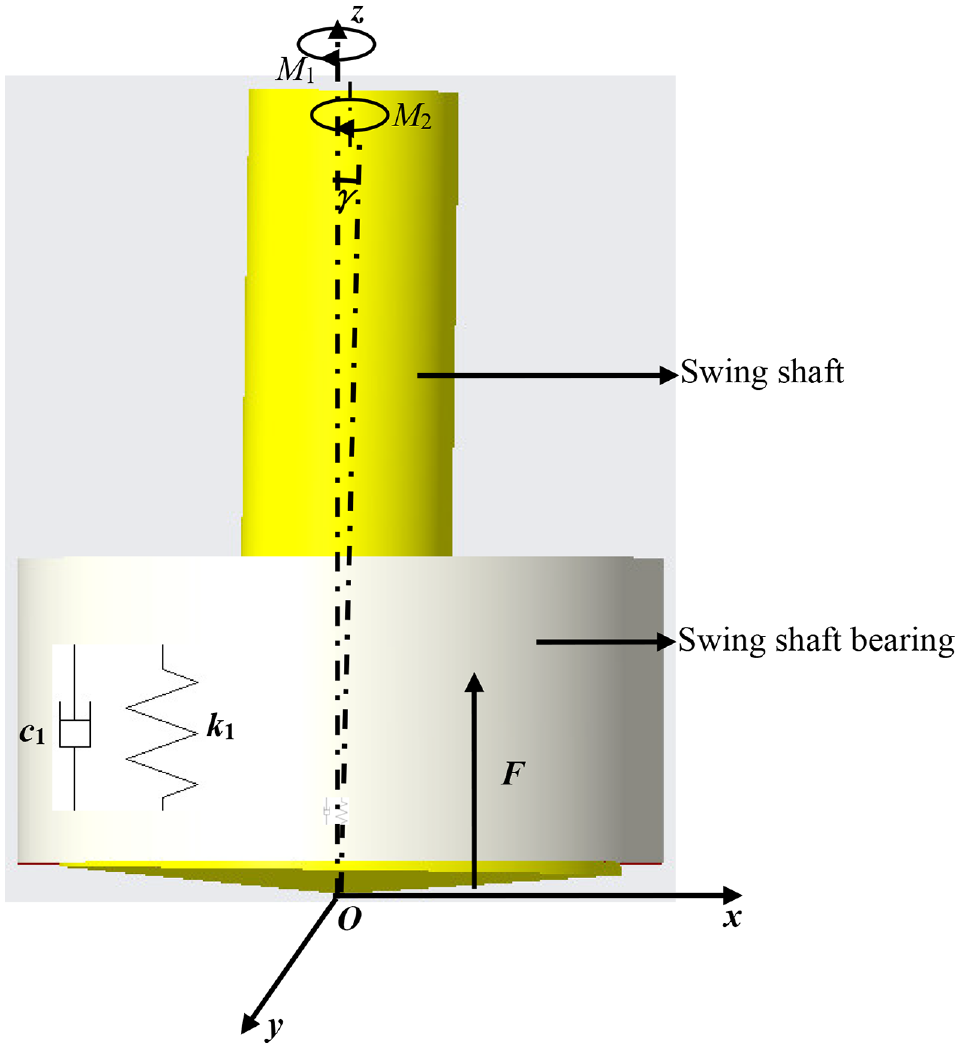
The dynamics model of the swing shaft is shown in Figure 7. The dynamics model is simplified as a spring-damping-mass model, and the concentrated mass represents the swing shaft. Furthermore, m3 denotes the mass of the swing shaft (kg), k1 is the equivalent stiffness between the swing shaft and the swing shaft bearing (N/m), c1 is the equivalent damping between the swing shaft and s the wing shaft bearing (N·S/m), F is the COF force (N), and M1 and M2 are torques around the center shafts of the eccentricities (N·m). During the COF process, the torques and the COF force drive the swing shaft movement.
Dynamics model of swing shaft.
The COF force (F) was calculated as follows 30 :

Where, nH is the shape limit coefficient of the die (n H ≥ 1, the specific value can be determined experimentally or by referring to the method of selecting this parameter in the calculation of the die forging pressure), 31 S is the contact area between the swing shaft and the forging part (mm2), nσ is the stress state coefficient of the contact surface between the swing shaft and the forging part, and σs is the yield stress of the forged part. S and nσ can be calculated as follows:
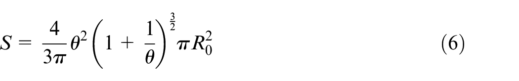
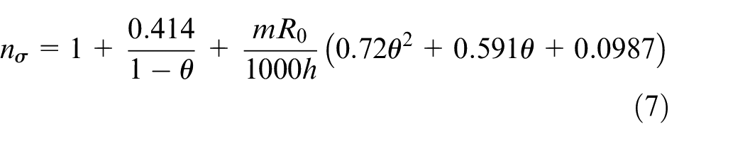
Where, R0 is the radius of the forging part (mm), h is the height of the forging part (mm), and m is the friction factor of plastic deformation. The relative movement of the lower die (θ) can be calculated using equation (8).
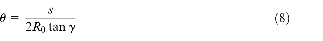
Where, s is the lower die movement of each turn (mm), and γ is the angle between the swing shaft axis and the z-axis.
In addition, torques (M1 and M2) can be calculated using the following equation:
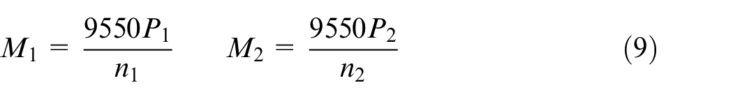
Where, P1 and P2 are the motor power (kW), and n1 and n2 are the rotation speeds of the eccentricity rings (rpm).
The dynamics simulation of the COF machine
The dynamics simulation model of the swing shaft-eccentricity rings system is shown in Figure 8. During the dynamics simulation process, the spherical pair was applied between the swing shaft and the swing shaft bearing, and a fixed pair was applied to the swing shaft bearing. In addition, torques (M1 and M2) and the COF force (F) were applied to the swing shaft. As a result of the simulation, the acceleration curve of Point 1 (Figure 8) was exported.
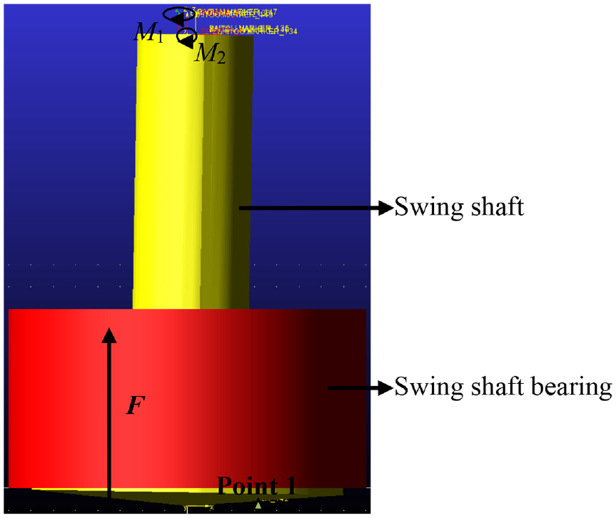
Dynamics simulation model of swing shaft-eccentricity rings system.
The dynamics simulation results of the swing shaft-eccentricity rings system are shown in Figure 9. When P1 was 40 kW and P2 was 40 kW, the acceleration at Point 1 varied periodically with time, and the amplitude of the acceleration was 1.96 m/s 2 .
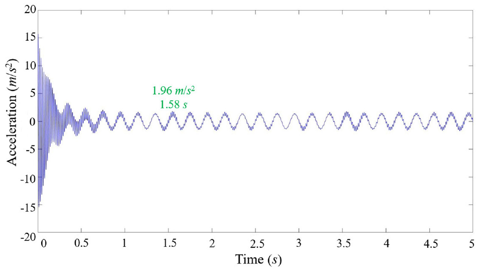
Simulation acceleration of Point 1 (P1 = 40 kW, P2 = 40 kW).
The verification experiment
An acceleration test experiment was conducted to verify the effectiveness of the simulation of the COF machine based on ADAMS. During the acceleration test experiment, the COF force and motor torques caused the swing shaft to move. An acceleration sensor was installed on the swing shaft to receive the acceleration signal. Subsequently, the acceleration signal was transformed into an electrical signal, which was conducive to the transmission, transformation, and preservation of the signal. Then, the electrical signal was amplified by a charge amplifier and transmitted to the LMS signal acquisition instrument. At this time, the electrical signal typically contains an interference signal. Therefore, the signal collected by the LMS signal acquisition instrument was preprocessed to reduce invalid signals. The analog signal was then converted into a digital signal using the A/D transformation of the signal acquisition system. Ultimately, the converted digital signal was transmitted to the LMS.Test.Lab software of the LMS signal acquisition instrument, and the signal was analyzed and disposed of in the software.
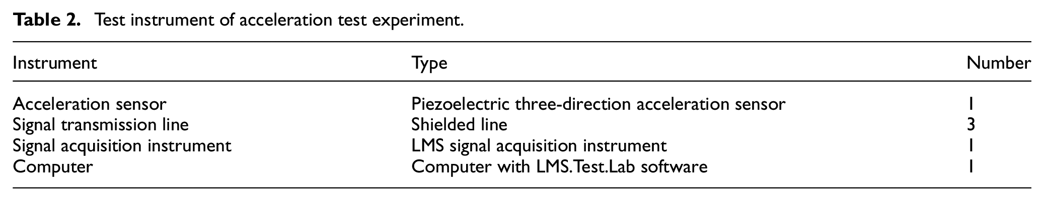
The acceleration test experiment is shown in Figure 10, and the main test instruments are listed in Table 2. As shown in Figure 11, an acceleration sensor was installed on the swing shaft to test its acceleration. The acceleration sensor was a piezoelectric three-directional sensor. During the COF process, the housing mass in the sensor squeezes the built-in piezoelectric chip as it moves, leading to a voltage signal. Subsequently, the voltage signal was converted into a charge signal by signal conditioning for acceleration measurement and processing. The three-directional acceleration sensor receives the acceleration signal of the swing shaft, transforms the acceleration signal into an electrical signal, and transmits it to the LMS signal acquisition instrument. The acceleration of the swing shaft can be viewed and analyzed using the LMS.Test.Lab software of the LMS signal acquisition instrument. Moreover, during the acceleration test experiment, the relative movement between the sensor signal transmission line and the swing shaft should be avoided. Furthermore, a shielded line should be used as the signal transmission line to avoid mutual interference among the signal transmission lines. Simultaneously, the signal transmission line should be fixed to avoid shaking, and the signal transmission line on the ground should avoid compression.
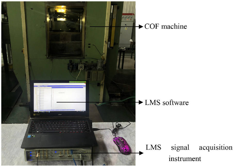
Acceleration test experiment.
Test instrument of acceleration test experiment.
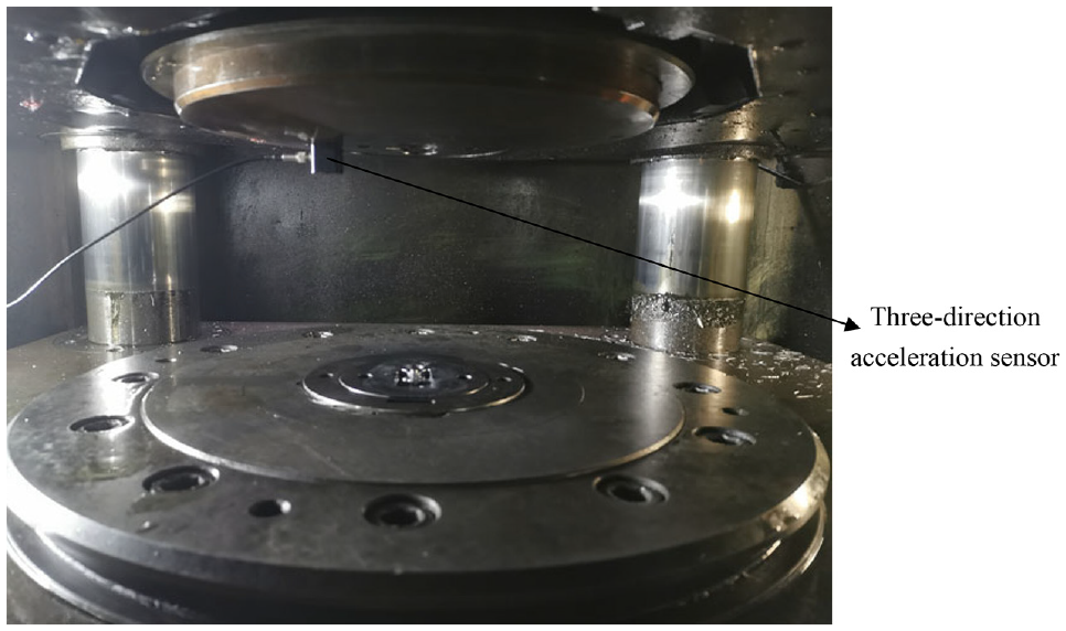
Installation site of three-direction acceleration sensor.
The results of the acceleration test are shown in Figure 12. Most of the time, the COF machine is a no-load state. When the time was 10.70 s, the COF machine was in the state of the COF process and the amplitude of the acceleration was 2.35 m/s 2 . Comparing the simulation acceleration (Figure 9) and the experimental acceleration (Figure 12) of the COF machine, the error of the simulation acceleration is acceptable (16%). The simulation of the COF machine based on ADAMS was effectively verified.
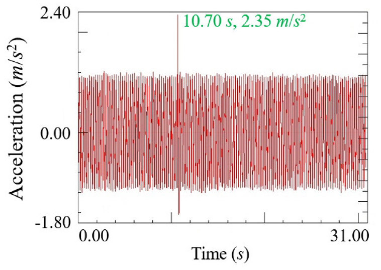
Experimental acceleration of Point 1 (P1 = 40 kW, P2 = 40 kW).
The structure optimization of the COF machine
Hua et al. 27 revealed that the vertical vibration of a COF machine is more drastic than its horizontal vibration, and has a much larger impact on the quality of the forged part. Consequently, for reducing the vibration of the COF machine, and improving the quality of the forged part, it is more effective to use a method for reducing the vertical vibration, rather than a method for reducing the horizontal vibration of the COF machine.
A structure optimization method for reducing vertical vibration is proposed in this study. In our method, an absorber composed of an elastic part, a damping part, and a mass block was installed on the swing shaft. The absorber was designed to absorb part of the vibration energy in order to reduce the vertical vibration of the swing shaft. The absorber design included the design of its mass, stiffness and damping mechanism.
Before the dynamics simulation of the optimized COF machine, a stability analysis of the vertical vibration of the optimized COF machine was carried out. The vertical dynamics model of the swing shaft is shown in Figure 13, where, z4 denotes the vertical displacement of the absorber (m), k2 is the equivalent stiffness between the swing shaft and the absorber (3.813 × 10⁷ N/m), c2 is the equivalent damping between the swing shaft and the absorber (1.127 × 10³ N·S/m), m4 is the equivalent mass of the absorber (60 kg). T is vertical external excitation of swing shaft (N).
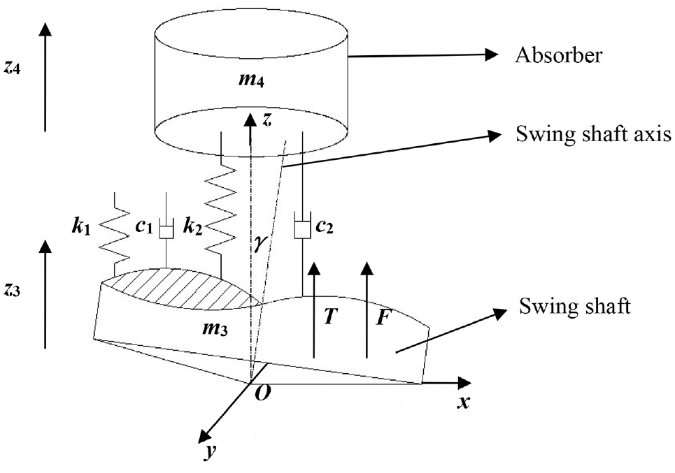
Vertical dynamics model of swing shaft.
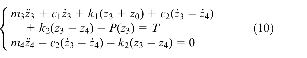
According to the generalized dissipation Lagrange principle, the vertical dynamic equation of the swing shaft can be expressed as equation (10).
Equation (10) can be converted into equation (11) 26 :
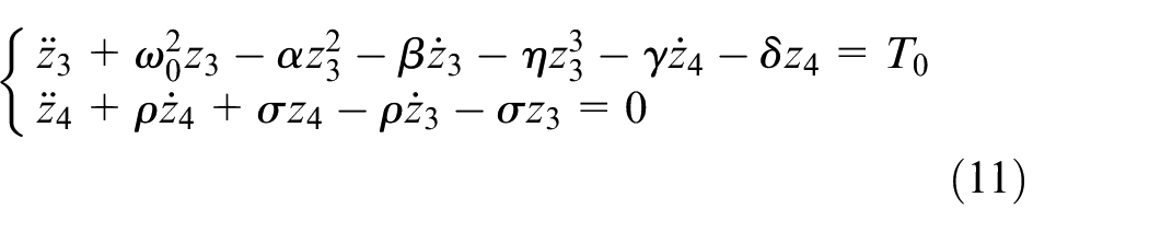
Where, ω0, α, β, η, T0, γ, δ, ρ, and σ are expressed as follows.
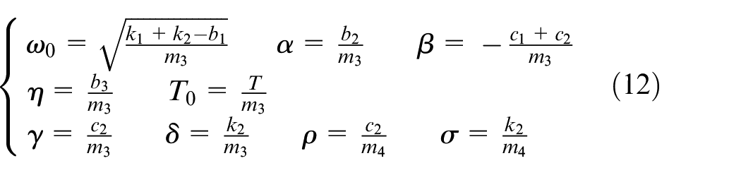
Where, b1, b2, and b3 are the parameters influencing the COF force. In terms of equation (11), several transitions occur.
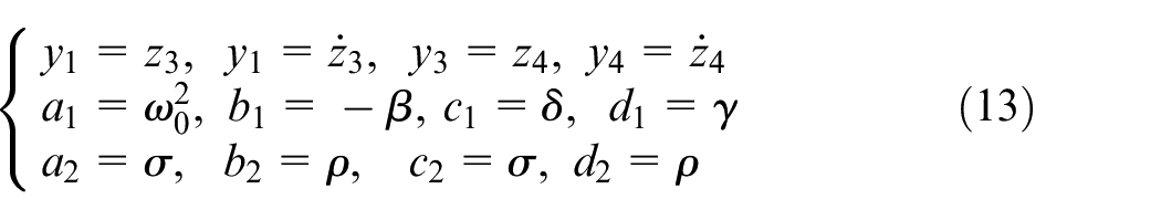
Equation (11) can be converted into the equivalent first order equation.
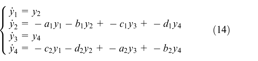
The Jacobian matrix in equation (14) at the origin can be expressed as:
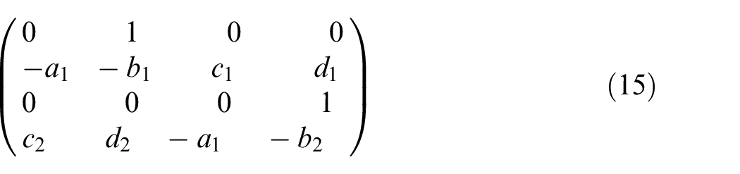
The characteristic equation corresponding to the Jacobian matrix can be expressed as equation (16).

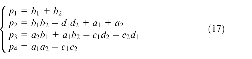
Where, p1, p2, p3, and p4 are obtained using equation (17).
The characteristic equation (16) is equivalent to equation (18).
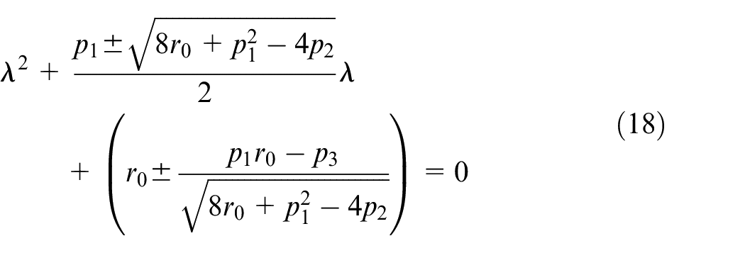
Where,
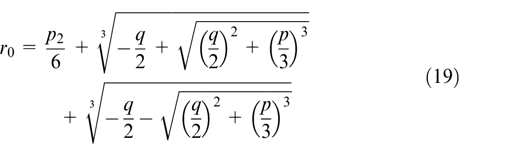

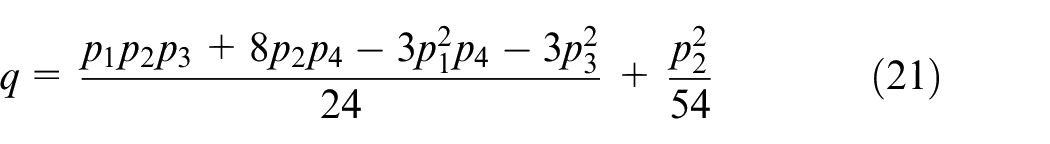
As for the characteristic equation (18), there are some transitions.
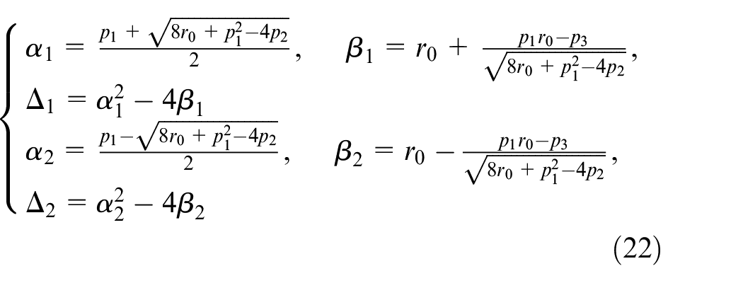
Subsequently, the characteristic equation (18) can be converted into characteristic equations (23, 24).


Based on the characteristic equations (23, 24) and the singularity stability theory, it can be observed that the vibration of the swing shaft will be unstable under the following conditions 32 :
When Δ1 < 0, α1 > 0, α2 = 0, β2 > 0, the solution of the characteristic equation (23) is a pair of conjugate complex roots with negative real parts, and the solution of the characteristic equation (24) is a pair of pure imaginary roots. When α1 = 0, β1 > 0, Δ2 < 0,α2 > 0, the solution of the characteristic equation (23) is a pair of pure imaginary roots, and the solution of the characteristic equation (24) is a pair of conjugate complex roots with negative real parts. The above two conditions correspond to the characteristic equation (16) with a pair of conjugate complex roots with negative real parts and a pair of pure imaginary roots, and the Hopf bifurcation is more likely to occur on the swing shaft.
When Δ2 < 0, β1 < 0, α2 > 0, the solution of the characteristic equation (23) is a positive real root and a negative real root, and the solution of the characteristic equation (24) is a pair of conjugate complex roots with negative real parts. When Δ1 < 0, α1 > 0, and β2 < 0, the solution of the characteristic equation (23) is a pair of conjugate complex roots with negative real parts, and the solution of the characteristic equation (24) is a positive real root and a negative real root. The above two conditions correspond to the characteristic equation (16) with a pair of conjugate complex roots with negative real parts and two real roots (one positive real root and one negative real root), and the chaos phenomenon tends to occur on the swing shaft.
By introducing the parameters of the COF machine into Eqs. (10)–(24), the Hopf bifurcation and chaos phenomena are less likely to occur on the swing shaft, and the vertical vibration of the optimized COF machine is therefore stable. Subsequently, a dynamics simulation of the optimized COF machine was performed to analyze the effect of reducing the vibration with the structure optimization.
The dynamics simulation model of the optimized swing shaft-eccentricity rings system is shown in Figure 14. During the dynamics simulation process, a spherical pair was applied between the swing shaft and the swing shaft bearing, and a fixed pair is applied to the swing shaft bearing. In addition, the torques (M1 and M2) and the COF force (F) are applied on the swing shaft. As a result of the simulation, the acceleration curve of Point 1 (Figure 14) was exported.
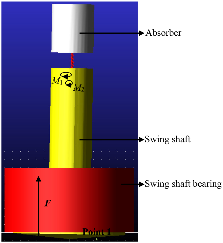
Dynamics simulation model of optimized swing shaft-eccentricity rings system.
The dynamics simulation results of the optimized swing shaft-eccentricity rings system are shown in Figure 15. When P1 was 40 kW and P2 was 40 kW, the amplitude of the acceleration was 1.225 m/s 2 . Comparing Figures 9 and 15, it can be observed that the vibration of the optimized COF machine was obviously reduced, which is conducive to improving the quality of the forged part.
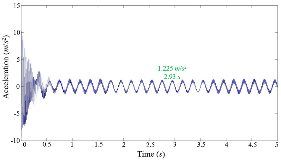
Simulation acceleration of Point 1 (P1 = 40 kW, P2 = 40 kW).
Conclusions
In this study, an automatic dynamic analysis of mechanical systems (ADAMS) was applied to conduct kinematics and dynamics simulations of the COF machine. The simulation of the COF machine was verified through an acceleration test experiment. Based on the simulation results, the kinetic and vibration performances of the COF machine were studied, and a structure optimization method for the COF machine was proposed. The following conclusions were drawn.
The simulation motion trail of the COF machine was the same as the motion trail obtained by numerical solving.
The magnitude and direction of ω1 (the angular velocity of the outer eccentricity ring) and ω2 (the angular velocity of the inner eccentricity ring) influence the motion trail of the COF machine. If the magnitude and direction are the same, the motion trail is a circle. If the magnitude is the same but the direction is different, the motion trail will be a curve. If the magnitude is different but the direction is the same, the motion trail will be a helix. If the magnitude and direction are different, the motion trail will be a rose curve.
Based on the singularity stability theory, the Hopf bifurcation and chaos phenomena are less likely to occur on the optimized COF machine, and the vibration of the optimized COF machine is therefore stable.
The structure optimization method of the COF machine is effective in reducing the vibration of the COF machine, which is beneficial to improving the quality of the forged part.
Footnotes
Declaration of conflicting interests
The author(s) declared no potential conflicts of interest with respect to the research, authorship, and/or publication of this article.
Funding
The author(s) disclosed receipt of the following financial support for the research, authorship, and/or publication of this article: The authors would like to thank the National Natural Science Foundation of China (No. 51575416), National Natural Science Foundation of China Youth Fund (52005375), China Postdoctoral Science Foundation (2020M672429) and the Fundamental Research Funds for the Central Universities (WUT: 2021IVB009) for the support given to this research.