
Abstract
The vibration of cold orbital forging (COF) machines is a major issue for the quality of forging parts. It is therefore necessary to investigate the vibration of COF machines and provide some effective methods for reducing the vibration. In this paper, horizontal and vertical dynamic models of COF machines are established. These dynamic models are then effectively verified by conducting experiments. By using dynamic models of the COF machine, the vibration performance of the COF machine is investigated. To investigate methods for reducing the vibration of the COF machine, the effects of some key parameters on the vibration of the COF machine are studied, which include the eccentricities and rotation angular speeds of the inner eccentricity ring and the outer eccentricity ring, the amplitude and frequency of external excitation, and the equivalent stiffness and equivalent damping between swing shaft and bearing. Investigative conclusions can be drawn: During the COF process, vertical vibration is more drastic than horizontal vibration. A larger absolute difference between the eccentricities of the inner eccentricity ring and the outer eccentricity ring contributes to reducing the horizontal vibration of the COF machine. A larger equivalent stiffness and a larger equivalent damping between the swing shaft and bearing, a smaller amplitude and a smaller frequency of the external excitation contribute to reducing the vertical vibration of the COF machine.
Introduction
Cold orbital forging (COF) is an advanced and complex incremental metal forming technology. 1 Compared with conventional forging, COF can reduce the forming force, improve the flowing capability of metal, and improve the loading state of the die. Therefore, COF is widely used to manufacture mechanical parts such as disks, rings, flanges, and gears. However, during the COF process, the COF machine is liable to vibrate due to the influence of the motor torque, external excitation, and COF force, which is detrimental to the quality of the forging part. To improve the quality of the forging part of the COF, investigations regarding the vibration of the COF machine and methods of reducing vibration are necessary.
Some scholars have conducted studies on COF. Regarding the COF process, Samołyk2,3 and Han and Hua4,5 investigated the deformation mechanism of parts in the COF. The forging force in the forging process was investigated by adopting the upper bound method 6 and the experimental method. 7 Regarding COF kinematics, Han et al.8,9 revealed the kinematic mechanism of the COF machine and obtained kinematic equations of the COF machine. Feng et al. 10 and Dong et al. 11 presented the influence of structural parameters on the kinetic locus of a COF machine. Regarding the COF application,12–15 investigated applications of COF in manufacturing spur bevel gears, gear racks, and rings. However, most studies on COF machines are focused on the COF process and kinematics of COF machines, but few have been performed on the vibration of COF machines.
COF machines are a type of metal forming machine. In recent years, many studies on the vibration of metal forming machines have focused on the vibration of cold rolling machines. A cold rolling machine is another type of metal forming machine that is used to manufacture strip steel. Liu et al. 16 and Bar and Świątoniowski 17 established a vertical dynamic model of a cold rolling machine with nonlinear external excitation. Lu et al.18,19 established a vertical dynamic model and a horizontal dynamic model, where the accuracy of the dynamic model was verified by comparing the simulation and experimental results. Kim et al.20,21 investigated several factors of vibration on a rolling machine, with the results showing that a small rolling force, small rotation speed of the work roll and a small chatter frequency contributed to reducing the vibration of the rolling machine. In addition, there are some investigations on the vibration of other metal forming machines. Ding et al. 22 presented a three-dimensional cutting force model of two-dimensional vibration-assisted micro end milling, and established a cutting process dynamic model of two-dimensional vibration-assisted micro end milling. Li et al. 23 built an extended dynamic model of milling machine considering mode coupling and process damping. Mei et al. 24 set up an accurate dynamic model for the numerical control machine feed system, and conducted the experiment to verify accuracy of the dynamic model. An et al. 25 adopted the virtual material method to build the flycutting machine model. Subsequently, the finite element method was applied to analyze the dynamic performance of the virtual material model. Relative to other metal forming machines, the kinematic mechanism and dynamic model of COF machines are more complicated; therefore, dynamic models of these metal forming machines cannot be applied to COF machines.
The objective of this paper is to investigate the vibration of COF machines. The kinematic mechanism of the COF machine is introduced, and a kinematic model of the COF machine is established. By analyzing the kinematic model and force state of the COF machine, horizontal and vertical dynamic models of the COF machine are established. To further verify the accuracy of the dynamic model, a COF experiment is performed. By using a dynamic model of a COF machine, the vibration performance of the COF machine is investigated. During the COF process, the horizontal vibration and vertical vibration of the COF machine vary periodically with time, where the vertical vibration is more drastic than the horizontal vibration. To investigate the methods for reducing vibration, the effects of some key parameters on the vibration of the COF machine are studied. Bringing variational parameters into the dynamic model of the COF machine, the results suggest that when the sizes and directions of the rotation angular speeds of the inner eccentricity ring and the outer eccentricity ring are identical, the horizontal vibration of the COF machine is minor. When the sizes and directions of the rotation angular speeds of the inner eccentricity ring and outer eccentricity ring are not identical, a larger absolute difference between the eccentricities of the inner eccentricity ring and outer eccentricity ring contributes to reducing the horizontal vibration of the COF machine. A larger equivalent stiffness and a larger equivalent damping between the swing shaft and bearing, a smaller amplitude and a smaller frequency of external excitation all contribute to reducing the vertical vibration of the COF machine.
Kinematic mechanism and kinematic model of the COF machine
Kinematic mechanism of the COF machine
The structure of a T630 COF machine can be seen in Figure 1. The COF machine mainly consists of four parts: a motor system, a swing shaft-eccentricity rings system, the cold rotary forging area of the forging part, and a hydraulic system. The motor system is the part transforming electricity energy to kinetic energy. The motor system produces horizontal torque, which is transmitted to the swing shaft-eccentricity rings system via power transfer shafts. Horizontal torque gives rise to the horizontal swing of the swing shaft-eccentricity rings system. The hydraulic system provides power for the vertical movement of the forging part. During the COF process, the forging part contacts the swing shaft directly, and a COF force is generated between the forging part and the swing shaft. The COF force and the vertical external excitation lead to vertical movement of the swing shaft-eccentricity rings system.
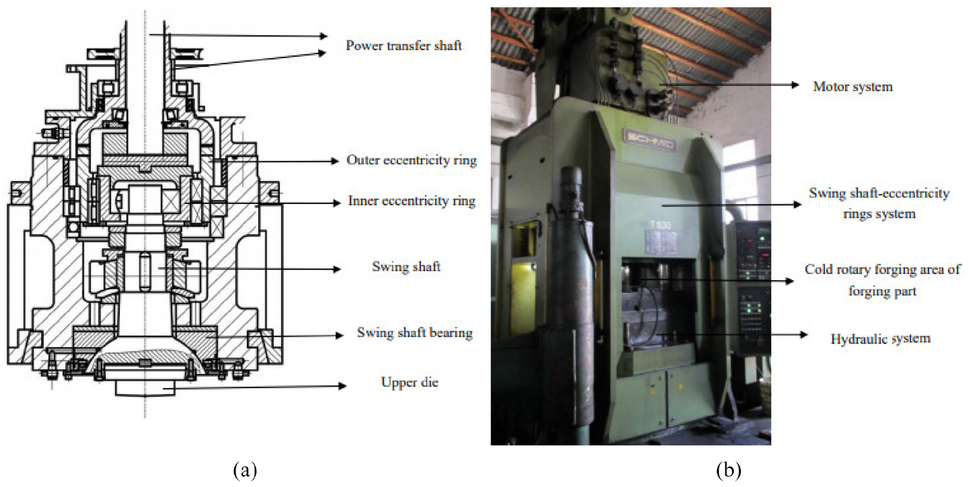
Structure (a) and equipment (b) of T630 COF machine.
During the COF process, horizontal torque, the COF force and the vertical external excitation lead to horizontal and vertical movements of the swing shaft-eccentricity rings system. The assembly of the swing shaft-eccentricity rings system is shown in Figure 2. The swing shaft-eccentricity rings system includes a swing shaft, an inner eccentricity ring and an outer eccentricity ring. Horizontal torque drives the inner eccentricity ring and outer eccentricity ring to rotate around their center axis. Meanwhile, the rotation of the outer eccentricity ring leads to the swing of the inner eccentricity ring around the center axis of the outer eccentricity ring. Therefore, the movement of the inner eccentricity ring is the resultant movement of rotation around the center axis of the inner eccentricity ring and the swing around the center axis of the outer eccentricity ring.
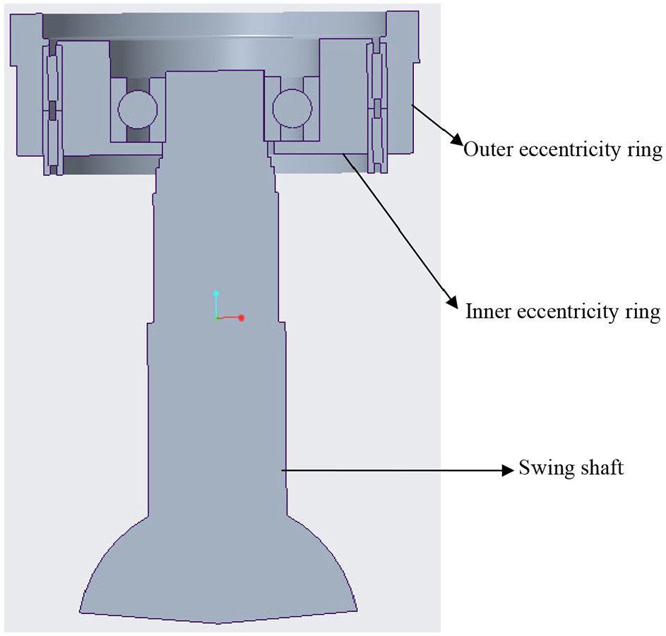
Assembly of swing shaft-eccentricity rings system.
Rotation of the inner eccentricity ring around the center axis of the inner eccentricity ring and the swing of the inner eccentricity ring around the center axis of the outer eccentricity ring lead to the swing of the swing shaft around the center axis of the inner eccentricity ring and outer eccentricity ring respectively. Therefore, the horizontal movement of the swing shaft is the resultant movement of the swing around the center axis of the inner eccentricity ring and the swing around the center axis of the outer eccentricity ring. Vertical movement of the swing shaft results from the COF force and vertical external excitation. During the COF process, the swing shaft contacts the forging part. The movement of the swing shaft directly influences the forging of the part.
Kinematic model of the COF machine
The structure of the outer eccentricity ring is shown in Figure 3. r01 is the outside radius of outer eccentricity ring (m), O1 is the center of the outside diameter, r02 is the inside radius (m), O2 is the center of the inside diameter, e1 is the eccentricity of the outer eccentricity ring (distance between point O1 and O2, m), h1 is the height of the outer eccentricity ring (m). The outer eccentricity ring is symmetric about the x axis on the xO1y plane, and the barycenter of the outer eccentricity ring (point B1) is on the x axis. The mass of the outer eccentricity ring (m1) can be calculated using equation (1).

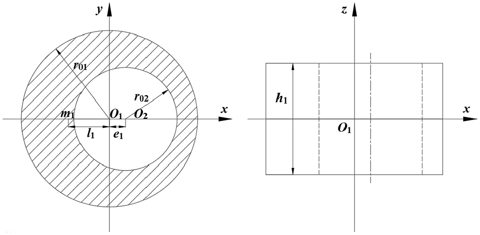
Structure of outer eccentricity ring.
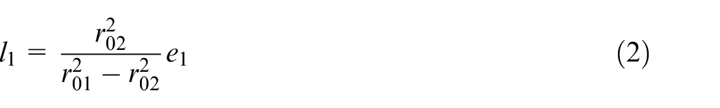
Where ρ0 represents the density of steel (the material of the eccentricity rings and the swing shaft are steel) (kg/m3). The distance between points m1 and O1 (l1, m) can be calculated by equation (2).
The outer eccentricity ring rotates around the z axis in the COF process. The rotational inertia of the outer eccentricity ring (J1) can be calculated via parallel-axis theory, as shown in equation (3).
The structure of the inner eccentricity ring is shown in Figure 4. r02 is the outside radius of the inner eccentricity ring (m), O2 is the center of the outside diameter, r03 is the inside radius (m), O3 is the center of the inside diameter, e2 is the eccentricity of the inner eccentricity ring (distance between points O2 and O3, m), and h2 is the height of the outer eccentricity ring (m). The inner eccentricity ring is symmetric about the x axis on the xO2y plane, and the barycenter of the inner eccentricity ring (point B2) is on the x axis. The mass of the inner eccentricity ring (m2) can be calculated by equation (4).

Structure of inner eccentricity ring.
The distance between point m2 and O2 (l2, m) can be calculated using equation (5).

The inner eccentricity ring rotates around the z axis in the COF process. J2 is the rotational inertia of the inner eccentricity ring, which can be calculated via parallel-axis theory, as shown in equation (6).
Figure 5 provides the structure of the swing shaft. The swing shaft consists of two cylinders and a cone, where the cone represents the upper die, r04 and r05 are the radius (m) of the upper cylinder and middle cylinder respectively, and d1, d2, and d3 are the heights (m) of the upper cylinder, middle cylinder, and cone respectively. The total height of the swing shaft (L) can be expressed by equation (7).

Structure of swing shaft.
The barycenter of the swing shaft (point B3) is on the rotation axis of the swing shaft. The mass of the swing shaft (m3) can be calculated by equation (8).

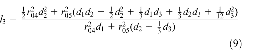
The distance between point m3 and O3 (l3, m) can be calculated by equation (9).
Assumptions should be taken to establish a kinematic model of a swing shaft-eccentricity rings system:
(1) The components of the swing shaft-eccentricity rings system are regarded as absolute rigid bodies without considering the effect of elastic deformation in the COF process.
(2) Kinematic pairs of the swing shaft-eccentricity rings system are considered to be close contacts without considering the effect of the space produced in the COF process.
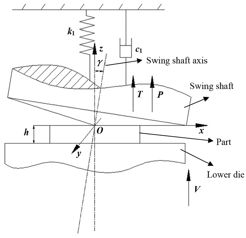
A kinematic model of the swing shaft-eccentricity rings system is shown in Figure 6, where OO3 is the swing shaft, and γ represents the angle between the swing shaft (OO3) and the z axis (swinging angle of the swing shaft). The distance of O1O2 is equal to e1 (eccentricity of the outer eccentricity ring (m)), and the distance of O2O3 is equal to e2 (eccentricity of the inner eccentricity ring (m)). The rotation of O1O2 around O1 represents the rotation of the outer eccentricity ring around its center axis, of which the angular velocity and angular displacement are ω1 (rad/s) and q1 (rad) respectively. The rotation and swing of O2O3 around O2 and O1 represent the rotation and swing of the inner eccentricity ring around the center axis of the inner and outer eccentricity ring respectively. The angular velocity and angular displacement of the rotation of O2O3 around O2 are ω2 (rad/s) and q2 (rad) respectively. The swing of O3 around O1 and O2 represent the swing of the swing shaft around the center axis of the outer and inner eccentricity ring respectively. The horizontal rotation and swing of the swing shaft-eccentricity rings system are caused by the output torque of the motor system, and the torques acting on O1O2 and O2O3 are M1 (N·m) and M2 (N·m) respectively. The vertical external excitation of the swing shaft and the COF force result in vertical vibration of the swing shaft.
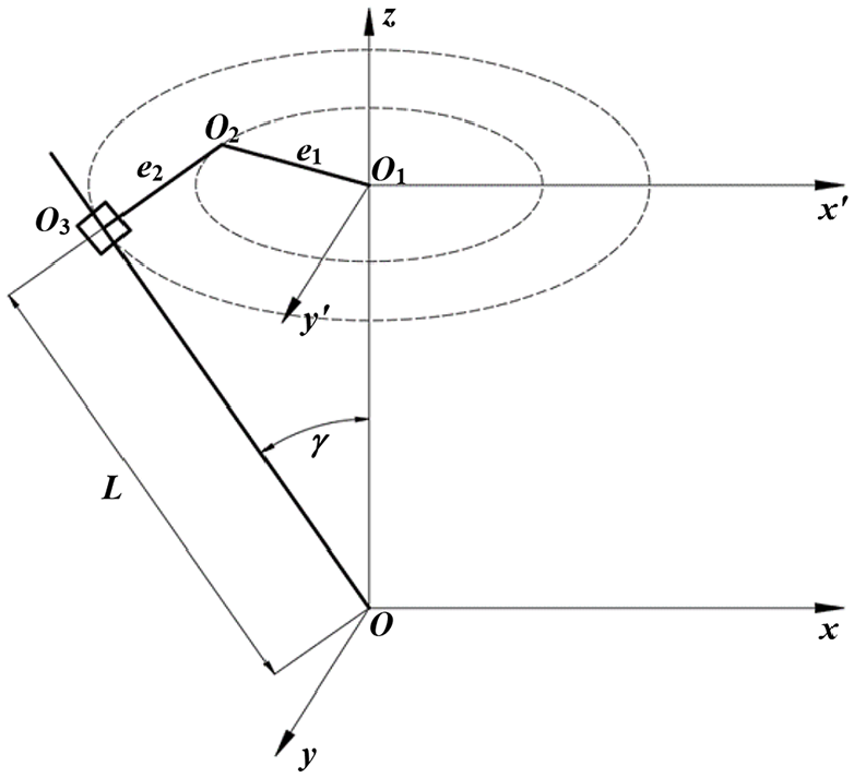
Kinematic model of swing shaft-eccentricity rings system.
Establishment and verification of the dynamic model of the COF machine
Horizontal dynamic model of the COF machine
As shown in the kinematic mechanism of the COF machine, the inner eccentricity ring and outer eccentricity ring are the driving components, and the swing shaft is the driven component. The structure of the eccentricity rings and the mechanical model of the eccentricity rings with two freedoms on the x′O1y′ plane are shown in Figures 7 and 8 respectively. The initial positions of O1O2 and O2O3 overlap with the x axis, and their initial phase angles are zero.
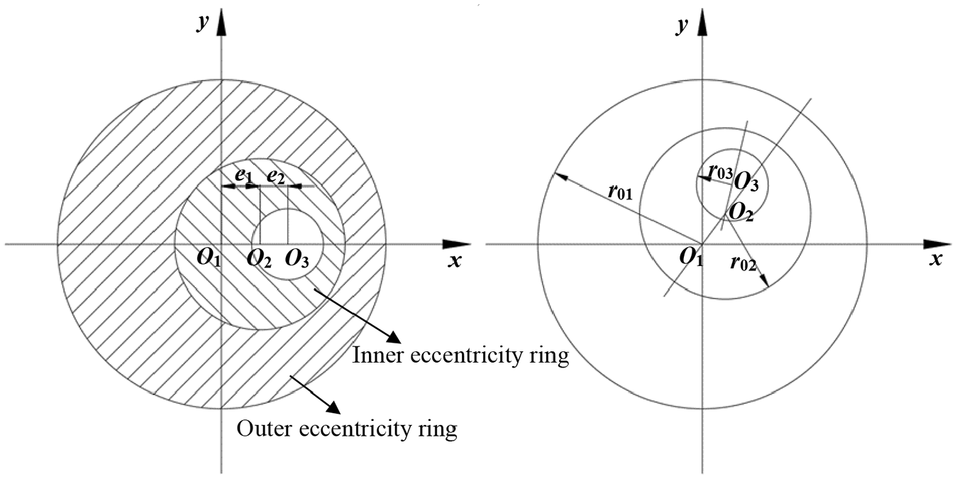
Structure of eccentricity rings.
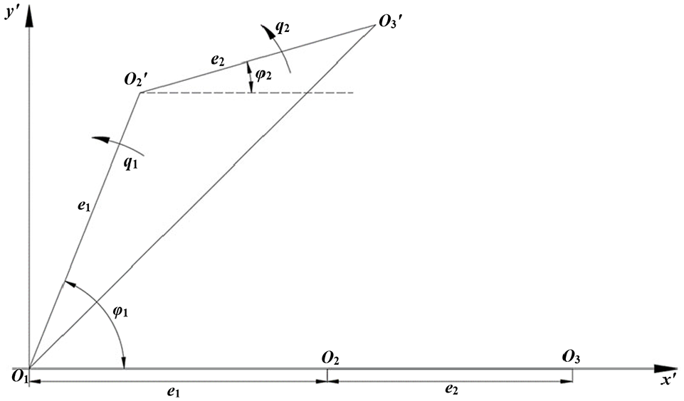
Mechanical model of eccentricity rings with two freedoms on x′O1y′ plane.
The torque of the motor is transmitted to the eccentricity rings by power transfer shafts. Cross sections of both ends of the output shafts will produce relative rotation under the torsion couple, where φ represents the relative torsional angle, which can be calculated by equation (10).
Where M represents the torsion couple acting on the power transfer shaft (N·m) and k0 can be calculated by equation (11).
Where G is the shear modulus of the material (GPa), D is diameter of the power transfer shaft (m), and l is the length of the power transfer shaft (m).
φ01 and φ02, which are the relative torsional angles of the two power transfer shafts under M1 and M2 respectively, can be calculated using equation (12).
Actual angular displacements of O1O2 and O2O3 (φ1 and φ2) consist of rotational angular displacement and relative torsional angle, which can be calculated by equation (13).
The movement track equations of B1(x1,y1), B2(x2,y2), and B3(x3,y3) on the x′O1y′ rectangular coordinate system can be obtained by the geometrical relationship shown in Figures 4 and 7. The movement track equations of B1, B2, and B3 can be expressed by equation (14).
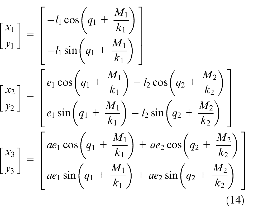
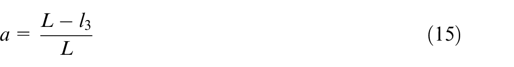
Where a can be calculated by equation (15).
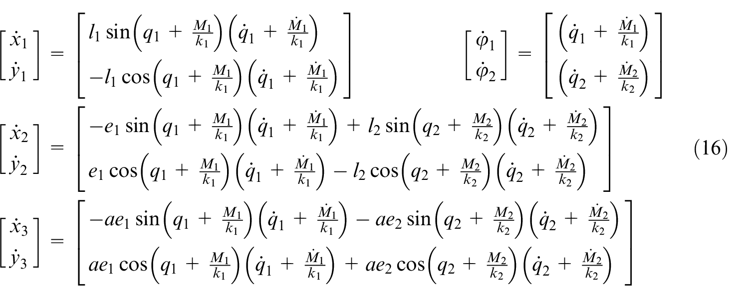
According to equation (14), the velocities of B1(x1,y1), B2(x2,y2), and B3(x3,y3) and the derivatives of φ1 and φ2 can be calculated by equation (16).
Based on Lagrange mechanics, the Lagrange equation of the swing shaft-eccentricity rings system can be expressed by equation (17).
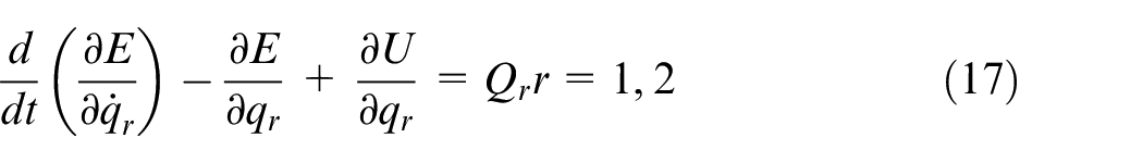
qr is the generalized coordinate of the swing shaft-eccentricity rings system, E is the kinetic energy of the swing shaft-eccentricity rings system, U is the potential energy of the swing shaft-eccentricity rings system, and Qr is the generalized force of the r-th generalized coordinate in the swing shaft-eccentricity rings system.
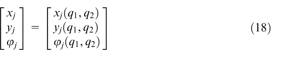
The barycenter displacement and angular displacement of the j-th component can be expressed as a function of generalized coordinates, as shown in equation (18).
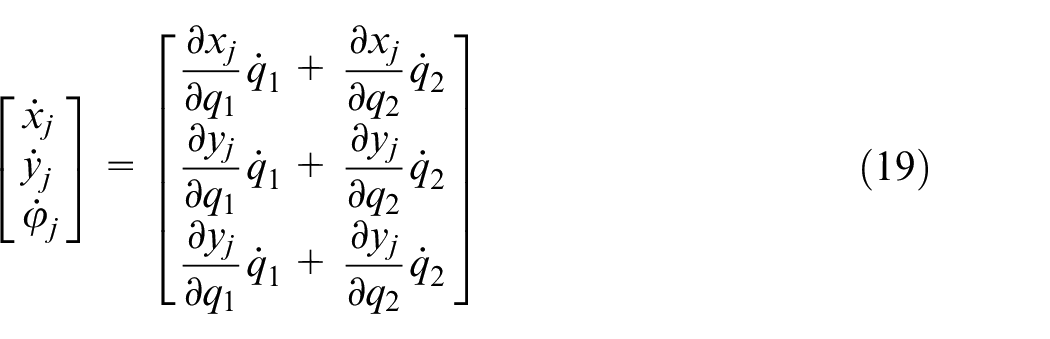
The barycenter velocity of the j-th component and the derivative of φj can be expressed by equation (19).
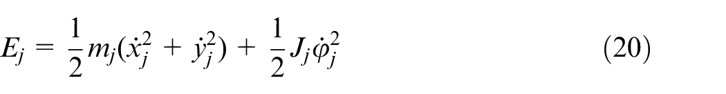
The kinetic energy of the j-th component in the swing shaft-eccentricity rings system can be calculated by equation (20).
Where
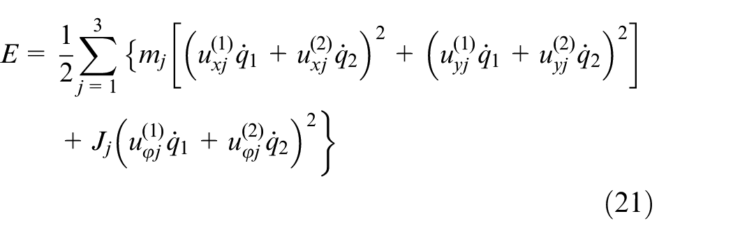
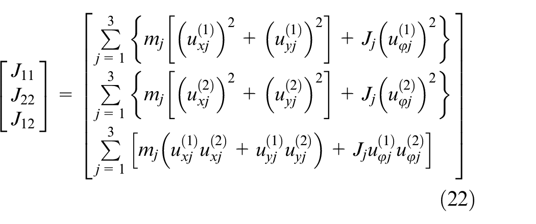
J11, J22, and J12 express the equivalent inertias of components in the swing shaft-eccentricity rings system, which can be shown by equation (22).
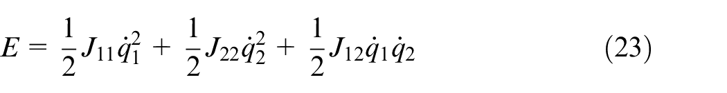
According to equations (21) and (22), the kinetic energy of the swing shaft-eccentricity rings system can be expressed by equation (23).
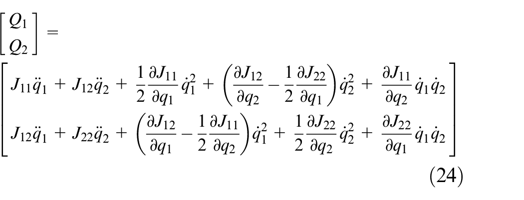
The dynamic equation of the swing shaft-eccentricity rings system is obtained by bringing equations (22) and (23) into equation (17), which is expressed as follows:
Where Q1 and Q2 are the generalized force of components in the swing shaft-eccentricity rings system, and can be obtained by virtual work principle, and δW1 (virtual work of generalized force) can be expressed as the following equation:

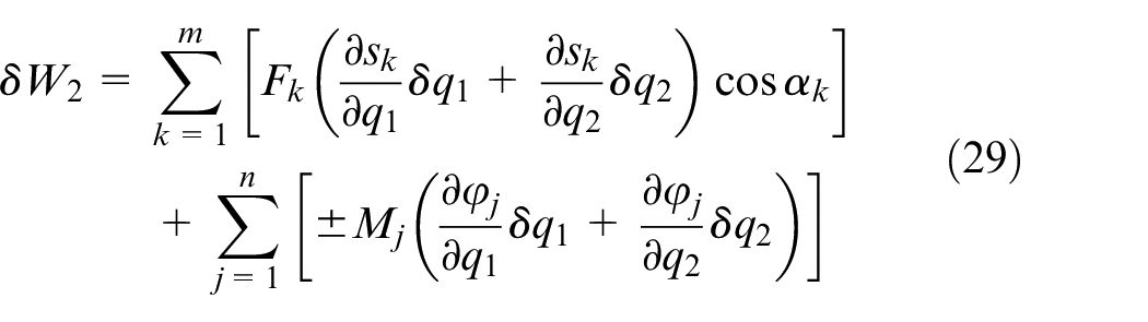
Where δq1 and δq2 are the virtual displacements corresponding to the generalized force, Fk (k = 1, 2, …, m) and Mj (j = 1, 2, …, n) are the external force and external torque on the swing shaft-eccentricity rings system respectively, and δW2 (virtual work of the external force and external torque) can be expressed by the following equation:
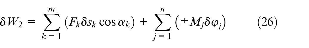
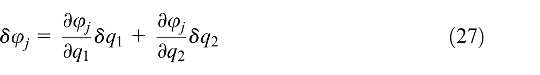
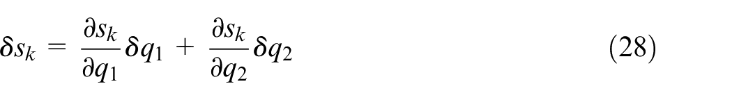
Where δφj is the angular virtual displacement caused by the external torque, δsk is the virtual displacement caused by external force, and αk is the angle between the external force and virtual displacement. δφj and δsk can be expressed as follows:
Introducing equations (27) and (28) into equation (26):
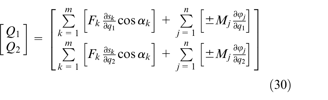
According to the virtual work principle, δW1 = δW2. Combining equations (25) and (29), Q1 and Q2 can be expressed by the following equation:
According to equation (30), Q1 and Q2 can be obtained:
Where
Introducing equations (31) and (33) into equation (24), M1 and M2 can be obtained. Afterward, the movement track of B3(x3, y3) can be obtained by bringing M1 and M2 into equation (14). The horizontal resultant velocity of B3(Vxy, m/s) can then be calculated by equation (34), and the horizontal resultant acceleration of B3(Axy, m/s 2 ) can be calculated by equation (35).
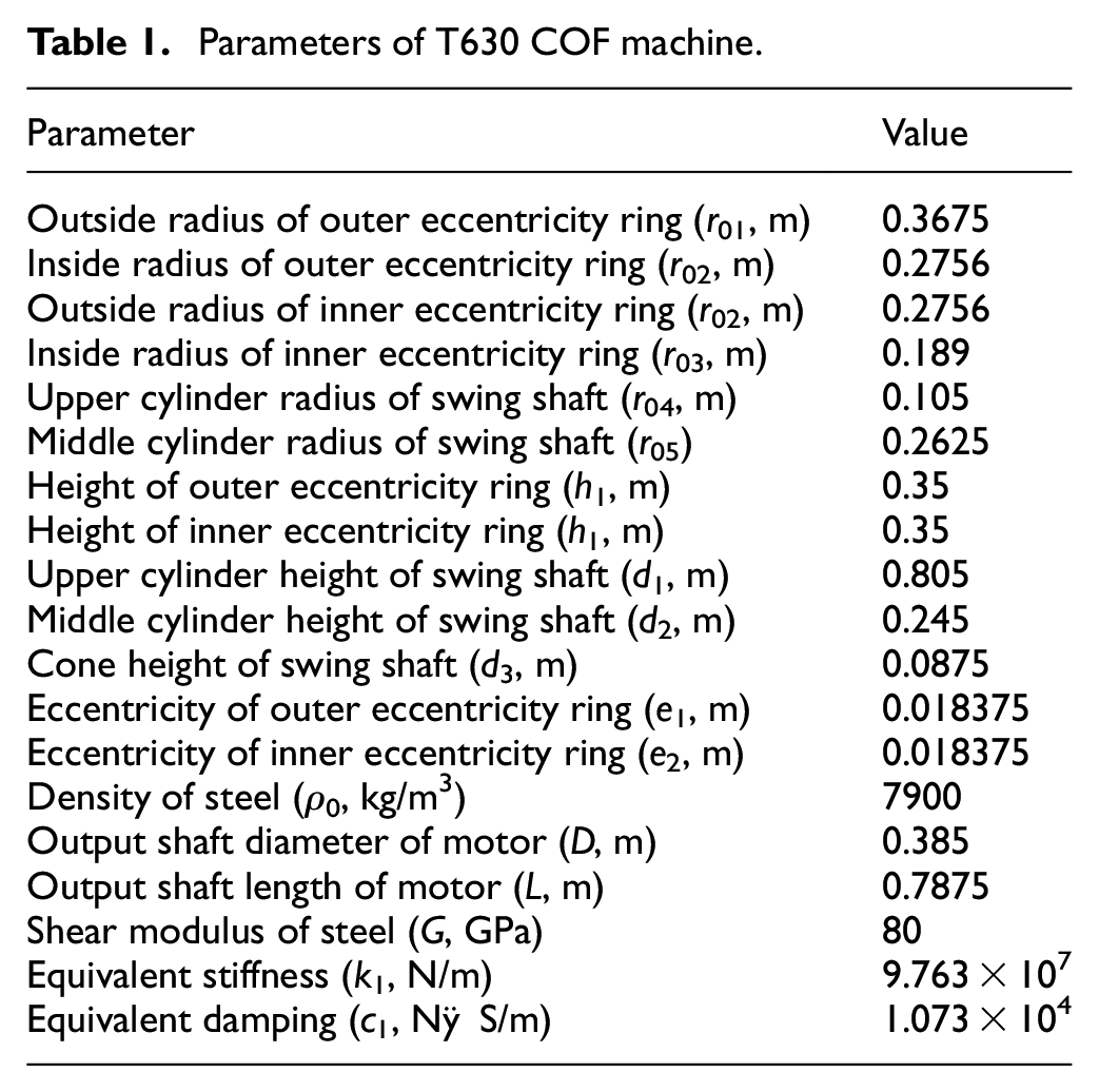
The parameters of the T630 COF machine are shown in Table 1.
Parameters of T630 COF machine.
Bringing the COF machine parameters into equations (24), (31), and (33) to (35), numerical simulation solutions can be obtained using MATLAB (numerical simulation solving software). The horizontal acceleration of the swing shaft is shown in Figure 9. In Figure 9, the horizontal acceleration of the swing shaft varies periodically with time, and the maximum horizontal acceleration amplitude of the swing shaft changes with ω1 and ω2. When the sizes of ω1 and ω2 are identical and the directions of ω1 and ω2 are opposite, the maximum horizontal acceleration amplitude of the swing shaft reaches the maximum value. When the size and direction of ω1 and ω2 are identical, the maximum horizontal acceleration amplitude of the swing shaft reaches its minimum value.
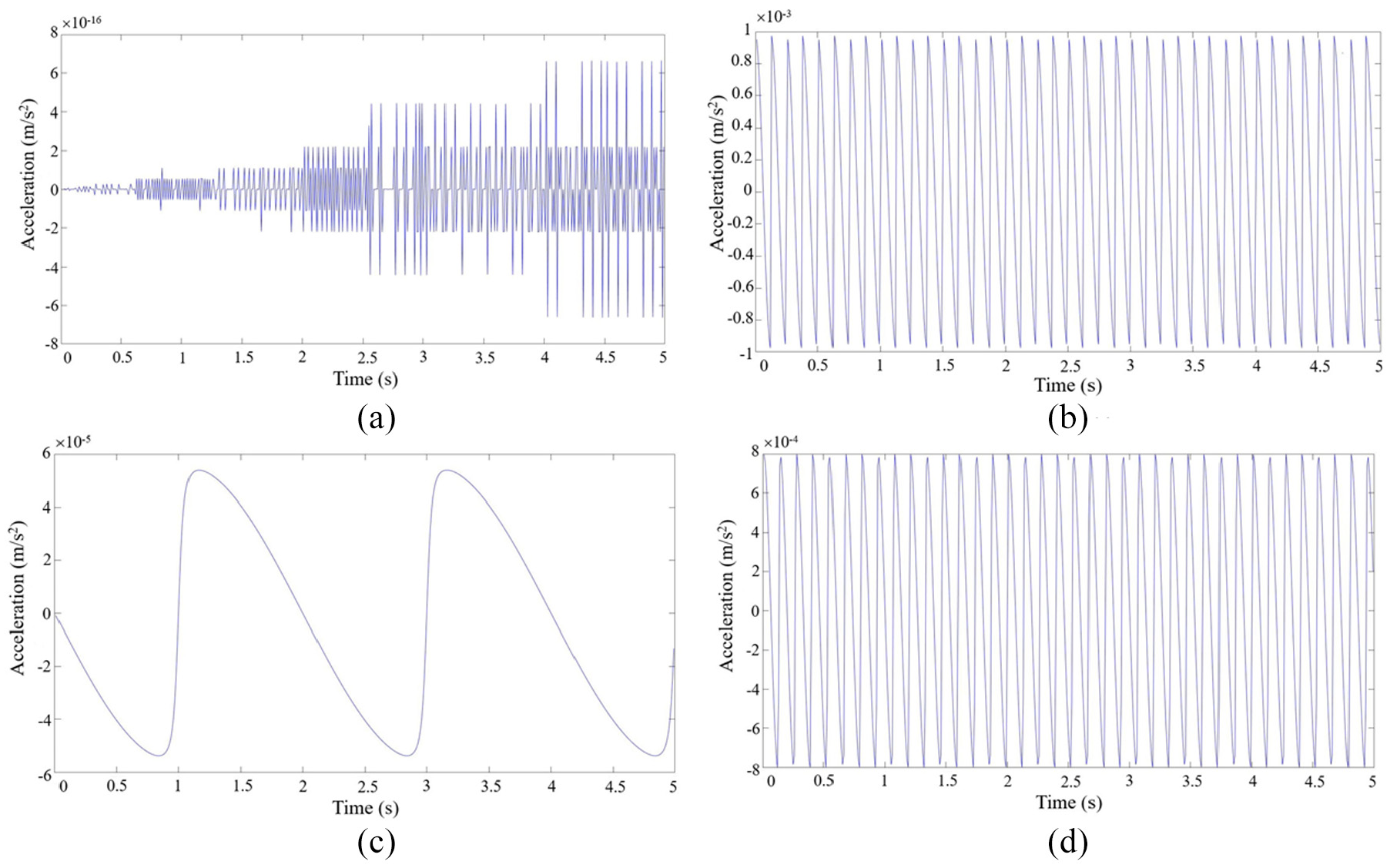
Horizontal resultant acceleration of swing shaft: (a) ω1 = 8π rad/s, ω2 = 8π rad/s, (b) ω1 = 8π rad/s, ω2 = −8π rad/s,(c) ω1 = 8π rad/s, ω2 = 7π rad/s, and (d) ω1 = 8π rad/s, ω2 = −7π rad/s.
Vertical dynamic model of the COF machine
The vertical dynamic model of the swing shaft is shown in Figure 10. The vertical dynamic model is simplified as a spring-damping-mass model, where the concentrated mass is equivalent to a swing shaft. m3 is equivalent mass of swing shaft (kg), k1 is the equivalent stiffness between the swing shaft and swing shaft bearing (N/m), c1 is the equivalent damping between the swing shaft and swing shaft bearing (N·S/m), and z3 is the vertical displacement of the swing shaft (m), of which the vertically upward direction is the positive direction of the vertical displacement. The thickness of the cylindrical part after the COF (h, m) can be calculated by h = h0 + z3, where h0 represents the thickness of the cylindrical part after the COF ignoring the effect of vibration (m). v is the vertical movement velocity of the forging part provided by the hydraulic system (m/s), P is COF force (N), and T is the vertical external excitation of the swing shaft (T = Fsinωt, N).
Vertical dynamic model of swing shaft.
The COF force (P) can be calculated using the following equation 26 :

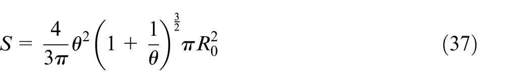
Where nH is the limit coefficient of die, S is the contact area between the swing shaft and the forging part (mm 2 ), nσ is the stress state coefficient of the contact surface between the swing shaft and the forging part, and σs is the yield stress of forging part. S and nσ can be calculated by follows:
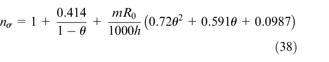
Where R0 represents the radius of the forging part (mm), and m is the friction factor of plastic deformation. The relative movement of the lower die (θ) can be calculated using equation (39).
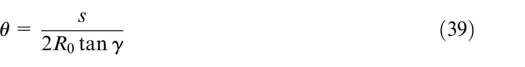
Where s is lower die movement of each turn (mm), and γ is the angle between the swing shaft axis and the z axis.
In the process of elastoplastic deformation, the COF force and displacement conform to nonlinear hysteresis due to the effect of periodic external excitation. The Taylor-series of P near z3 = 0 is expanded as follows:
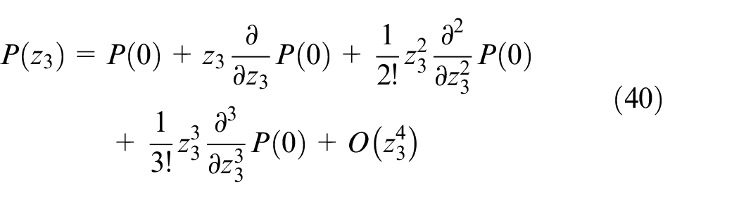
Where P(0) represents the steady-state COF force, and ΔP(z3) is the COF nonlinear hysteretic force, which can be expressed by equation (41).

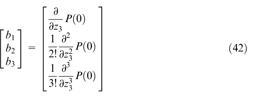
b1, b2, and b3 can be expressed by the equation below:
Combining equations (40) to (42), P can be expressed by the following equation:

According to the generalized dissipation Lagrange principle, the vertical dynamic equation of the swing shaft can be expressed by equation (44).

Where z0 is the equilibrium point in the process of COF. In the process of steady-state COF

Introducing equations (41), (43), and (45) into equation (44), the following equation can be gained:

Equation (46) can then be converted into equation (47):

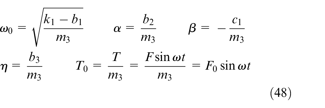
Where ω0, α, β, η, and T0 can be expressed by the follow.
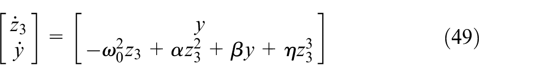
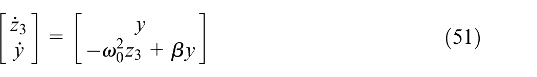
Equation (47) can be expressed as the following first-order equation by decreasing the order:
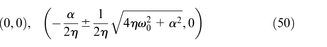
The singularity of the vertical dynamic system of the swing shaft can be obtained as follows:
After linearly processing equation (49), the following can be obtained:
The characteristic equation of equation (51) is shown as follows:

The solution of equation (49) is shown as follows:
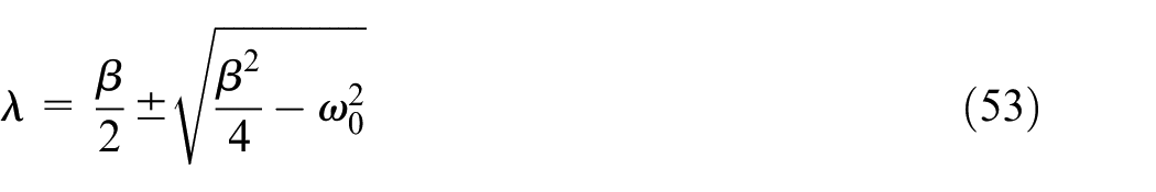
According to the singularity stability theory, the following can be obtained:
(1) When β < −2ω0 (b2 <
(2) When β > 2ω0 (b2 >
(3) When −2ω0 < β < 0 (
(4) When 0 < β < 2ω0 (0 < b2 <
(5) When β = 0, the solution of equation (53) is a pure virtual root, and the vertical dynamic system of the swing shaft exhibits stable periodic motion.
Bringing the 6300 KN COF machine parameters into equation (48), it can be determined that solution of equation (53) is a virtual root with a negative real part (−2ω0 < β < 0), and the singularity of the vertical dynamic system of the swing shaft is a stable node. Therefore, the vertical vibration of the swing shaft is relatively stable.
The nonlinear term of the vertical dynamic equation of the swing shaft is a weak nonlinear term. Equation (47) can then be converted into equation (54), where ε represents a small parameter.

Where:


Where σ is the tuning factor. Bringing equation (56) into equation (54), equation (57) can be obtained.

According to climax method, the solution of equation (57) can be in the following form.


Where φ = ωt + θ. Taking the quadratic derivative of equation (58) with respect to t and bringing it into the left side of equation (57), equation (61) can be obtained.

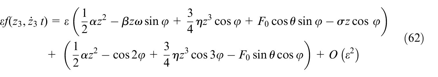
According to equations (55) and (58) to (60), the right side of equation (57) is shown as equation (62).
According to the equivalent coefficient method, the ε term of equations (61) and (62) is the same, and equation (63) can be obtained.
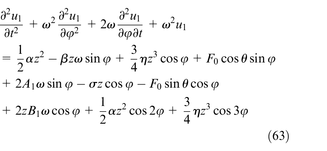
Eliminating the duration term of equation (63), the following equations can be obtained:
Bringing equation (66) into equation (58), the approximate analytical solution of z3 can be obtained as follows:
When the vertical motion of the swing shaft is periodic motion, the derivatives of z and φ are 0 and ω respectively. Bringing equations (64) and (65) into equations (59) and (60) and eliminating θ and σ, the amplitude-frequency response equation of the swing shaft can be obtained:
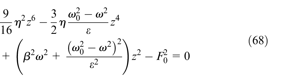
Where z represents the maximum vertical vibration amplitude of the swing shaft (m). As shown in the amplitude-frequency response equation, ω0, ω, β, η, and F0 influence the vertical vibration of the swing shaft.
Bringing the COF machine parameters into equation (47), numerical simulation solutions can be obtained via MATLAB (numerical simulation solving software). The vertical acceleration of the swing shaft is shown in Figure 11. The vertical acceleration amplitude-frequency curve of the swing shaft is shown in Figure 12. As shown in Figures 11 and 12, the vertical acceleration of the swing shaft is low-frequency vibration that varies periodically with time. Peak values of the frequency amplitude diagram of vertical vibration arise at 4 and 61 Hz. Compared to horizontal vibration, the vertical vibration is more drastic. The vertical vibration of the swing shaft has a much larger impact on the quality of the forging part than the horizontal vibration. The validity of the vertical dynamic model of the swing shaft will then be verified in the following, and a method of reducing the vertical vibration will be investigated.
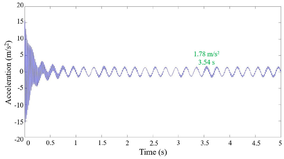
Vertical acceleration of swing shaft (F = 81,267 N).
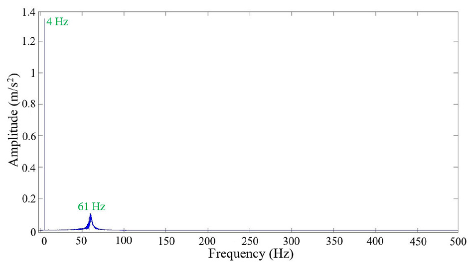
Vertical acceleration amplitude-frequency curve of swing shaft (F = 81,267 N).
Verification experiment of the dynamic model of the COF machine
The dynamic model of the COF machine has been established. Before using the established dynamic model to investigate the effects of key parameters on the vibration of the COF machine, the effectiveness of the dynamic model needs to be verified. As shown in Figure 13, verification experiment is performed on a T630 COF machine to verify the accuracy of the dynamic model. In the experimental process, the angular velocities of the inner eccentricity ring and outer eccentricity ring are 8π rad/s, and the hydraulic system drives the forging part to move upwards. In Figure 14, a unidirectional acceleration sensor is installed on the swing shaft. During the COF process, the vertical acceleration signal of the swing shaft is acquired by the acceleration sensor, and the vertical acceleration signal is transmitted to the LMS signal acquisition instrument. The vertical acceleration signal of the swing shaft can then be viewed and analyzed with LMS software.
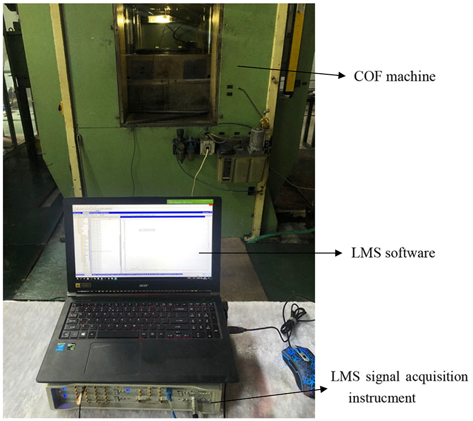
Verification experiment of dynamic model.
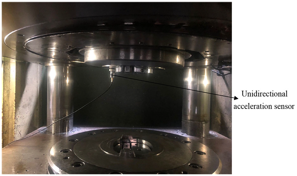
Installation site of unidirectional acceleration sensor.
In the LMS software, the vertical acceleration signal of the swing shaft is fast Fourier transformed. The time-domain signal of the vertical acceleration of the swing shaft is transformed to a frequency-domain signal. The experimental vertical acceleration amplitude-frequency curve of the swing shaft is shown in Figure 15, where it can be seen that vertical vibration of the swing shaft is a low-frequency vibration, and the frequencies of vertical acceleration with a high amplitude are approximately 4 and 69 Hz. Comparing Figures 12 and 15, the simulation frequencies of vertical acceleration with a high amplitude are very close to the experimental frequencies. The dynamic model of the COF machine is verified effectively.
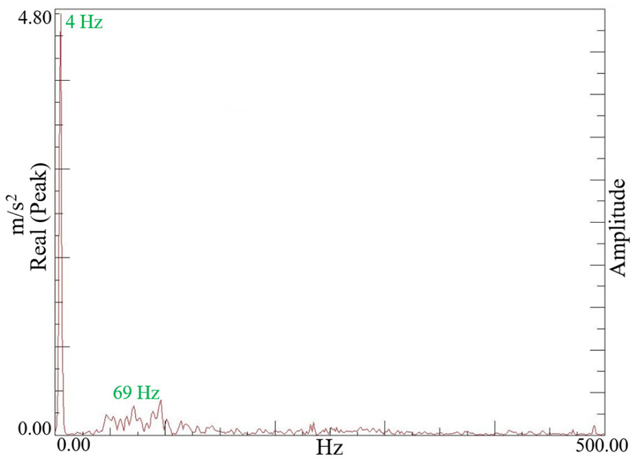
Vertical acceleration amplitude-frequency curve of swing shaft (F = 81,267 N).
Effects of key parameters on the vibration of the COF machine
As shown in the dynamic model of the COF machine, e1 and e2 (eccentricities of eccentricity rings) influence the horizontal vibration of the swing shaft. ω0 (the relative parameter of the equivalent stiffness between the swing shaft and bearing), ω (the relative parameter of the frequency of external excitation), β (the relative parameter of the equivalent damping between the swing shaft and bearing), and F0 (the relative parameter of the amplitude of external excitation) have the influence on vertical vibration of swing shaft. To investigate methods for reducing the vibration of the swing shaft, the effects of e1, e2, ω0, ω, β, and F0 on the vibration of the swing shaft will be investigated in this section.
The sum of e1 and e2 is 36.75 mm, and the peak value of the horizontal acceleration of the swing shaft with a variation of e1 (e1 = 1, 2, 3, …, 35 mm) is shown in Figure 16. In Figure 16(a), if ω1 is 8π rad/s and ω2 is 8π rad/s, the minimum peak value of horizontal acceleration occurs when e1 is 10 mm. The peak value of the horizontal acceleration varies with the variation in e1, but the variation is negligible.
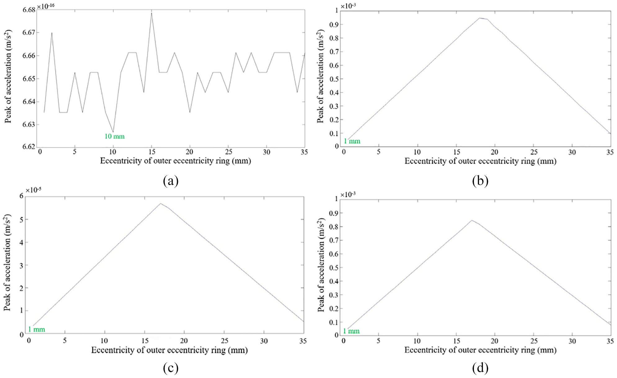
Peak value of horizontal acceleration of swing shaft with variation of e1: (a) ω1 = 8π rad/s, ω2 = 8π rad/s, (b) ω1 = 8π rad/s, ω2 = −8π rad/s, (c) ω1 = 8π rad/s, ω2 = 7π rad/s, and (d) ω1 = 8π rad/s, ω2 = −7π rad/s.
In Figure 16(b) to (d), if the size or direction of ω1 and ω2 are different, then the variation tendency of the peak value with the variation in e1 is similar. The minimum peak value of the horizontal acceleration arises when e1 is 1 mm. When the size or direction of ω1 and ω2 are different, the horizontal vibration is lighter with a larger absolute value of the difference between e1 and e2.
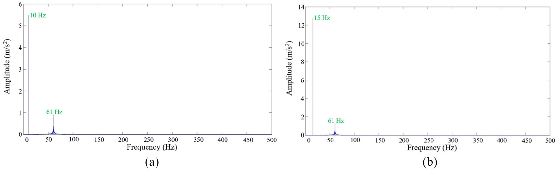
Figure 12 represents the vertical acceleration amplitude-frequency curve of the swing shaft when the value of ω0 is 146,400 N/kg·m. When the values of ω0 are 196,400 or 246,400 N/kg·m, FFT of the vertical acceleration of the swing shaft is shown in Figure 17. The amplitude of the highest peak decreases and the frequency of another peak increases as ω0 increases. According to equation (48), reducing the mass of the swing shaft, increasing the equivalent stiffness, and reducing the COF force can increase the value of ω0 and contribute to reducing the vertical vibration of the swing shaft.
Vertical acceleration amplitude-frequency curve of swing shaft: (a) ω0 = 196,400 N/kg·m and (b) ω0 = 246,400 N/kg·m.
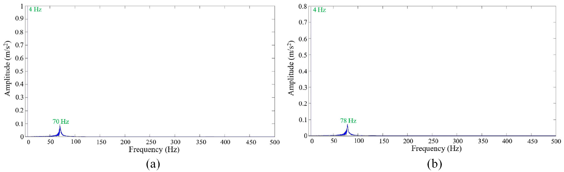
Figure 12 represents the vertical acceleration amplitude-frequency curve of the swing shaft when ω is 25.12 rad/s. When the values of ω are 62.8 or 94.2 rad/s, the FFT of the vertical acceleration of the swing shaft is shown in Figure 18. The amplitude of the highest peak and another peak increase as ω0 increases. Decreasing the frequency of external excitation can decrease the value of ω and will be beneficial to reducing the vertical vibration of the swing shaft.
Vertical acceleration amplitude-frequency curve of swing shaft: (a) ω = 62.8 rad/s and (b) ω = 94.2 rad/s.
When the values of β are −22.82 or −30.08 N·S/kg·m, the vertical acceleration amplitude-frequency curve of the swing shaft is shown in Figure 19. Comparing Figures 12 and 19, the amplitude of the second highest peak becomes slightly higher as value of β increases. According to equation (48), increasing the equivalent damping can decrease the value of β and will help to slightly reduce vertical vibration of the swing shaft.
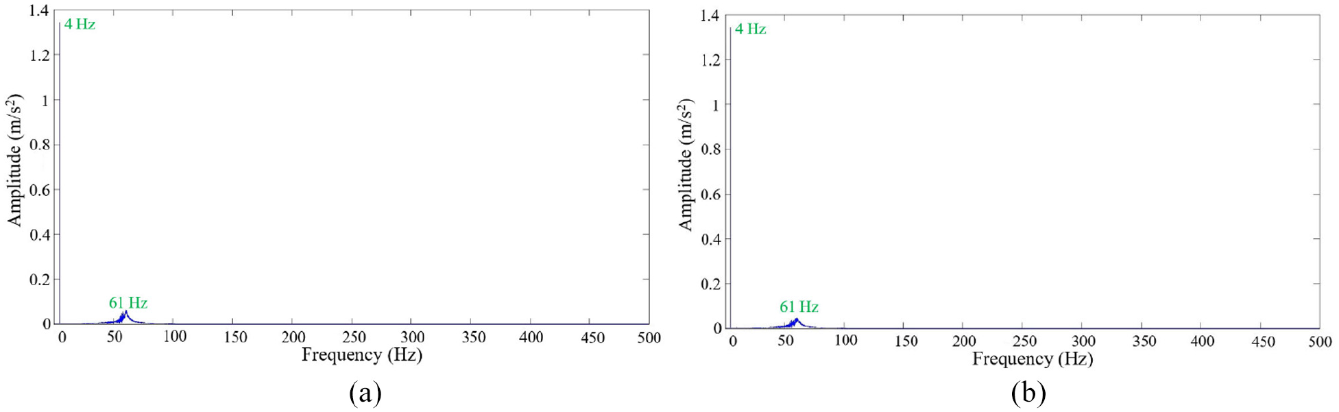
Vertical acceleration amplitude-frequency curve of swing shaft: (a) β = −22.82 N·S/kg·m and (b) β = −30.08 N·S/kg·m.
Figure 12 represents the vertical acceleration amplitude-frequency curve of the swing shaft when F0 is 117.926 N/kg. When the values of F0 are 212.4369 or 226.9478 N/kg, the FFT of the vertical acceleration of the swing shaft is shown in Figure 20. The peak value of the highest peak becomes higher as F0 increases. According to equation (48), decreasing the amplitude of the external excitation can decrease the value of F0 and will contribute to reducing the vertical vibration of the swing shaft.
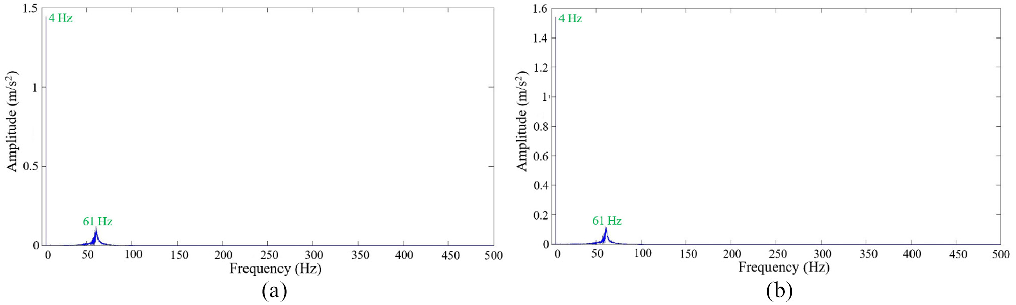
Vertical acceleration amplitude-frequency curve of swing shaft: (a) F0 = 212.4369 N/kg and (b) F0 = 226.9478 N/kg.
Conclusions
In this study, horizontal and vertical dynamic models of COF machines were established. The dynamic models were effectively verified by performing the vibration measurement experiment of the swing shaft. Using the dynamic model, the effects of several key parameters on the vibration of the swing shaft were investigated. Some conclusions can be drawn as follows:
The horizontal vibration and vertical vibration of the COF machine vary periodically with time, and the vertical vibration is more drastic than the horizontal vibration.
When the sizes and directions of the rotation angular speeds of the inner eccentricity ring and outer eccentricity ring are identical, the horizontal vibration of the COF machine is minor. When the sizes and directions of the rotation angular speeds of the inner eccentricity ring and outer eccentricity ring are not identical, a larger absolute difference between the eccentricities of the inner eccentricity ring and the outer eccentricity ring contributes to reducing the horizontal vibration of the COF machine.
A larger equivalent stiffness and a larger equivalent damping between the swing shaft and bearing, a smaller amplitude and a smaller frequency of external excitation contribute to reducing the vertical vibration of the COF machine.
Footnotes
Declaration of conflicting interests
The author(s) declared no potential conflicts of interest with respect to the research, authorship, and/or publication of this article.
Funding
The author(s) disclosed receipt of the following financial support for the research, authorship, and/or publication of this article: The authors would like to thank the National Natural Science Foundation of China (No. 51575416), 111 Project (B17034), Innovative Research Team Development Program of Ministry of Education of China (No. IRT17R83), the National Natural Science Foundation of China Youth Fund (No. 52005375), and the China Postdoctoral Science Foundation (2020M672429) for the support given to this research.