
Abstract
In the drilling process of horizontal and highly deviated well sections, cuttings are deposited on the lower side of annulus under the action of gravity during its transport, which affects the normal drilling operation. A variety of cuttings removal tools have emerged and achieved good results, but they are only effective when the drill string is rotating, while it is difficult to ensure the removal effect of cuttings in sliding drilling. In the drilling process of directional well and horizontal well, rotary drilling is sometimes difficult to meet the requirements of wellbore control, and sliding drilling is often used at this time. Therefore, there is an urgent need for a tool that can effectively remove cuttings in sliding drilling. In the present work, an efficient vortexing cuttings removal tool (VCRT) has been developed and the Computational Fluid Dynamics (CFD) simulation technology was used to study the cuttings removal mechanism of VCRT. The cuttings removal effect under the action of VCRT was compared with that of the conventional cuttings removal tool (CCRT) and the conventional drill pipe. The results show that VCRT has good cuttings removal effect in both sliding and rotary drilling conditions. The average cuttings volume fraction under the action of VCRT during sliding drilling is 59% lower than that of the conventional drill pipe, and 26% lower than that of CCRT. The average cuttings volume fraction under the action of VCRT during rotary drilling is 78% lower than that of the conventional drill pipe, the removal efficiency is similar to CCRT, but VCRT can send more cuttings into the annulus. The research reveals the mechanical mechanism of VCRT which provides a scientific basis for the cuttings removal mechanism of VCRT.
Keywords
Introduction
With the continuous development and improvement of drilling technology, horizontal well and extended-reach well have been more and more used. In the drilling process of horizontal and highly deviated well sections, cuttings will be deposited on the lower side of the borehole under the action of gravity, and it is easy to form the cuttings bed, which is difficult to be removed. The cuttings bed will cause backing pressure and increase torque and friction of drill string, make downhole instruments unable to work normally, and seriously affect the safety and the efficiency of drilling. If the cuttings in the borehole cannot be removed timely, it will cause stuck drills, broken drilling tools, and even lead to wellbore abandoned.1,2 In addition, the cuttings also increase the difficulty of casing running and cementing, affect the quality of cement cementing, and cause the interflow of oil, gas, and water layers. Therefore, if the cuttings bed cannot be cleaned timely and effectively, it will cause many complex problems, seriously affect the drilling speed, increase the drilling cost, and cause unnecessary losses.
In order to study the hole cleaning problems and the cuttings migration laws in the borehole annulus of horizontal wells, many researchers have carried out relevant laboratory experiments, field tests and theoretical research, and established empirical and theoretical models to describe the cuttings migration laws. Nguyen and Rahman
3
proposed a three-layer model to describe the deposition and migration of cuttings in extended-reach and horizontal well sections. In this model, the annulus is consisted with three layers: the upper layer is the fluid flow layer, the middle layer is the layer with variable cuttings concentration, and the lower layer is a cuttings bed with uniform cuttings concentration. Based on the theory of solid-liquid two-phase flow theory, Guoet al.
4
established a three-layer dynamic migration model of cuttings in the whole section of an extended-reach well. The study found that the flow rate has a great influence on the formation rate of the cuttings bed, the erosion rate and the well flushing time. Sayindla et al.
5
studied the hole cleaning efficiency of oil-based drilling fluids and water-based drilling fluids with similar viscosity distributions. Experiments show that oil-based drilling fluids have better hole cleaning performance than water-based drilling fluids when the drill string is not rotated. Olawale et al.
6
studied the effect of low-viscosity drilling fluid and drill string rotation on hole cleaning through experimental analysis and graphical evaluation. The results show that low-viscosity drilling fluid can erode the cuttings bed faster, and drill string rotation can speed up cleaning. Sun et al.
7
studied the influence of rotational speed and drilling fluid viscosity on the distribution of cuttings bed by numerical simulation method, and put some suggestions according to the simulation results: during drilling operations, when the tripping speed is 0.25−0.75 m/s, the viscosity of the drilling fluid should be less than 30
Over the years, researchers have proposed a variety of solutions to the cuttings bed removal problems.9–13 The general cuttings bed removal methods include: improving the performance of drilling fluids, increasing the rotational speed of drilling tools, increasing the annulus fluid velocity, and mechanical cuttings removal methods, etc. However, these methods have their limitations, such as increasing the performance of the drilling fluid will increase the extra cost, excessive rotation speed will lead to the failure of the drilling tools, and the velocity of the annulus fluid is limited by the pump. In order to avoid the problems mentioned above, scholars improved the drill string structure to improve the cuttings removal effect and the improved drill string is called cuttings removal tool.
The cuttings removal tool is an effective hole cleaning tool, which has both hydraulic and mechanical functions and can be used to destroy and remove the cuttings bed. Cuttings removal tools can improve the migration state of cuttings particles during drilling, and effectively solve the problems of cuttings accumulation during drilling in horizontal wells and extended reach wells. Van Puymbroeck and Williams 14 of VAM company introduced a downhole mechanical cleaning device (Figure 1(a)). The experimental results show that the device can reduce the time of hole cleaning, and can better destroy the cuttings bed in both highly deviated and horizontal well sections. Wylie et al. 15 and Rodman et al. 16 introduced a cuttings removal tool of DBS company, the tool is called Cuttings Bed Impeller (CBI) (Figure 1(b)), which can clean the wellbore effectively. Heitmann et al. 17 has developed a cuttings removal tool with a helical blade, the tool is machined with a helix on the drill string. When working, the helix will form a forced vortex in the annulus, thereby improving the drilling fluid disturbance ability to improve the efficiency of hole cleaning. Chen et al. 18 used CFD simulation technology to study the flow characteristics of annulus flow field under the action of Effective HydroClean Drill Pipe (EHCDP). The mechanism of EHCDP was revealed, and the influence of the helical structure on the flow characteristics of the annular fluid was analyzed. Liu et al. 19 used the Euler multiphase flow model to simulate the cuttings migration in the horizontal well section. By comparing the distribution of cuttings in the annulus of the wellbore before and after the use of the cuttings removal tool, the engineering parameters for the best hole cleaning effect are obtained.
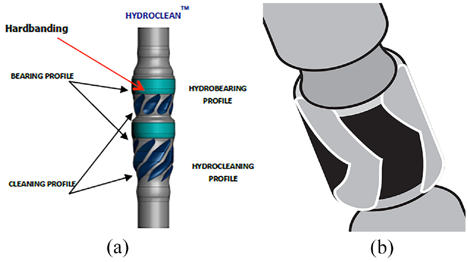
Typical cuttings removal tools. (a) hydroclean of VAM and (b) Cuttings Bed Impeller (CBI) of DBS.
However, these cuttings removal tools are fixed on the drill string and rotate synchronously with the drill string. The cuttings removal effect is restricted by the rotation speed of the drill string. Moreover, the drill string does not rotate during sliding drilling in the horizontal section, which makes the cuttings removal tool ineffective.
In order to improve the efficiency of cuttings removal and solve the problem of cuttings deposit on the lower side of the borehole during sliding drilling, Sinopec East China Oilfield Service Corporation developed an efficient Vortexing Cuttings Removal Tool (VCRT), which has an internal turbine structure and can be driven by the flow of drilling fluid to rotate the tool. The turbine structure allows VCRT to play an effective role during sliding drilling. In order to study the cuttings removal effect of VCRT, this paper uses CFD method to simulate the annulus flow field under the action of VCRT. As a comparison, the CCRT and the conventional drill pipe model were simulated under the same boundary conditions.
Structure design and working principle
VCRT is consisted with an upper joint, a lower joint, spiral channel on the upper and lower joint, a turbine with three rotating arris structures, and the structure of VCRT is shown as Figure 2. The basic parameters of VCRT model established in this paper are as follows: the outer diameter of the drill pipe is 168.3 mm, the maximum outer diameter of the spiral channels and the rotating arris structures are both 214.0 mm, and the rotating arris structure length is 199.3 mm. Assume that this tool is used with an

VCRT model.

VCRT working principle.
CFD model of VCRT
Physical model
According to the parameters of VCRT model (as shown in Figure 2), the simplified physical model is established. The total length of the model is 1.4 m, drill pipe diameter is 168.3 mm, borehole diameter is 233.2 mm, the rotating arris structure length is 0.2 m. The simplified physical model is shown as Figure 4.

Physical model.
Mesh model
Considering that the solid boundary of VCRT changes with time, the flow of the annulus fluid is unsteady. The sliding mesh method is adopted to simulate the unsteady flow, the fluid is divided into different computational domains as shown in Figure 5(c), then the governing equations of the fluid can be solved in each subdomain. There are relative movements between different zones, and the interpolation method is used to transfer field data on the interface, and the information of each subdomain is exchanged by converting the relative velocity into the absolute velocity. The meshing of the model is shown in Figure 5(a), the meshing at the inner wall is shown in Figure 5(b), and the meshing at the cross section of the rotating zone is shown in Figure 5(c) and (d). A finer boundary layer mesh is arranged on the wall. The total number of elements is 2,718,459 and the total number of nodes is 818,846.

Mesh model. (a) meshing of the model, (b) mesh the outer surface of the tool, (c) different computational zones, and (d) fine mesh at the boundary.
Calculation model
CFD software ANSYS Fluent is used for the model calculation, and the Euler method is used to study the effect of VCRT on the two-phase flow field of drilling fluid and cuttings. There are three two-phase flow models based on the Euler method in ANSYS Fluent: Mixture Model, Volume of Fluid (VOF) Model, and Eulerian Model. The VOF model is suitable for stratified or free surface flow, the mixing and Eulerian models are suitable for phase mixing or separation flow, or the volume fraction of discrete phases exceeds 10%. In this paper, the real flow in the wellbore annulus can be simplified as a two-phase flow, the first phase is drilling fluid, the second phase is cuttings, and cuttings are widely distributed in the wellbore annulus, therefore the mixed model is suitable to analyze the working condition during the horizontal wells drilling.
Turbulence model
The Realizable

Where ρ is the density of the mixed phase,
Theoretical model of cuttings migration
Cuttings migrate in the wellbore with the drilling fluid. The drilling fluid is liquid phase, and the cuttings are solid phase. They form a multiphase mixed fluid, and the governing equation is as follows.22–24
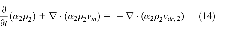
(1) The continuity equation is given by:


Where m is the mixture quality, kg;
(2) Momentum equation:
where
(3) Energy conservation equation 22 :

Where
(4) Relative speed and drift speed of cuttings
The relative velocity (also referred to as the slip flow velocity) is defined as the velocity of the cuttings relative to the velocity of drilling fluid. 22

Where
The relationship between the drift velocity and the relative velocity of cuttings is:

The mixed model in ANSYS Fluent uses an algebraic slip formulation. The basic assumption of the algebraic slip mixed model is to specify the algebraic relationship of the relative velocities, and the local equilibrium between the phases should be achieved on short spatial scales.

Where

Where

Where
(5) Volume fraction equation of cuttings
From the continuity equation of the cuttings, the volume fraction equation of the cuttings can be obtained 22 :
Two-phase flow model
The parameters of drilling fluid and cuttings are shown as Table 1, the length of the initial distribution of cuttings is 1.4 m, the height is 20 mm, the volume fraction of cuttings on the lower side of the wellbore is 0.95, and the density gradually decreases along the height direction. The initial cuttings distribution is shown in Figure 6.
The parameters of drilling fluid and cuttings.
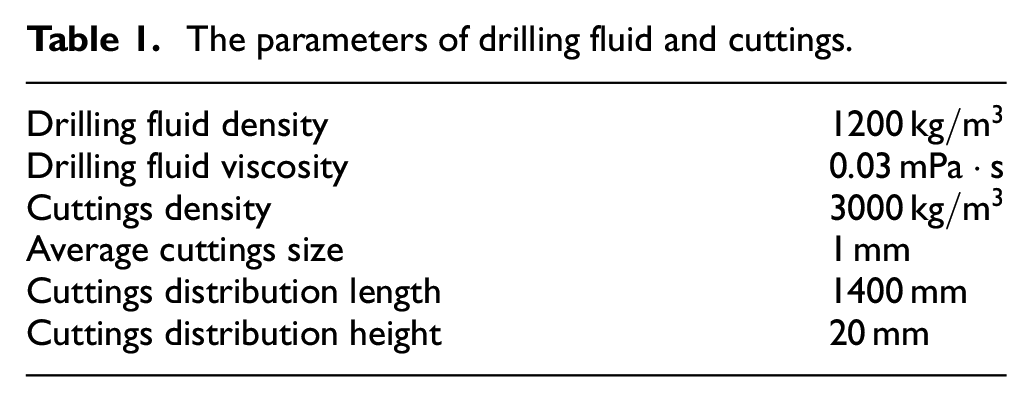
Initial cuttings distribution.
Volume fraction (

In this paper, Drilling fluid is the first phase, and cuttings are the second phase.
Boundary conditions
During rotary drilling, the drill string rotating speed is 60
The boundary conditions of VCRT, CCRT, and conventional drill pipe during rotary drilling.

The boundary conditions of VCRT, CCRT, and conventional drill pipe during sliding drilling.

Cuttings removal effect of VCRT
Sliding drilling condition
In the construction of directional wells, sliding drilling is still common in some geographic locations. During sliding drilling, the cuttings removal effect of CCRT will be seriously affected due to the non-rotating drill string. However, even if the drill string is not rotating, VCRT can also drive the rotating structure to rotate under the action of drilling fluid to achieve cuttings removal. The sections of 0.55 (section A), 0.70 (section B), 0.90 m (section C), line 1 and line 2 were selected to study the cuttings removal efficiency of VRCT, CCRT, and conventional drill string under sliding drilling conditions, and the location is shown as Figure 7.
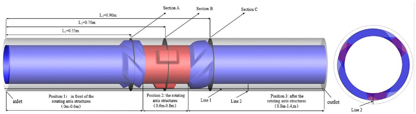
The location of section (a–c) and the path line l, 2.
Figure 8 shows that when sliding drilling 0.42 s, the distribution of cuttings at section A, B, and C under the action of the conventional drill pipe do not change significantly. CCRT has the spiral structure, therefore the cuttings at section C have reduced, but there are still a certain amount of cuttings distributed on the lower side of the annulus. However, under the action of VCRT, the cuttings on the lower side of the wellbore at section C are significantly reduced, and most of the cuttings are distributed on the higher side of the annulus. During sliding drilling, although the drill string does not rotate, the internal turbine of VCRT drives the external rotating arris structures to rotate. The rotating arris structures agitate the cuttings at the bottom of the borehole and carry them into the higher side of the annulus.
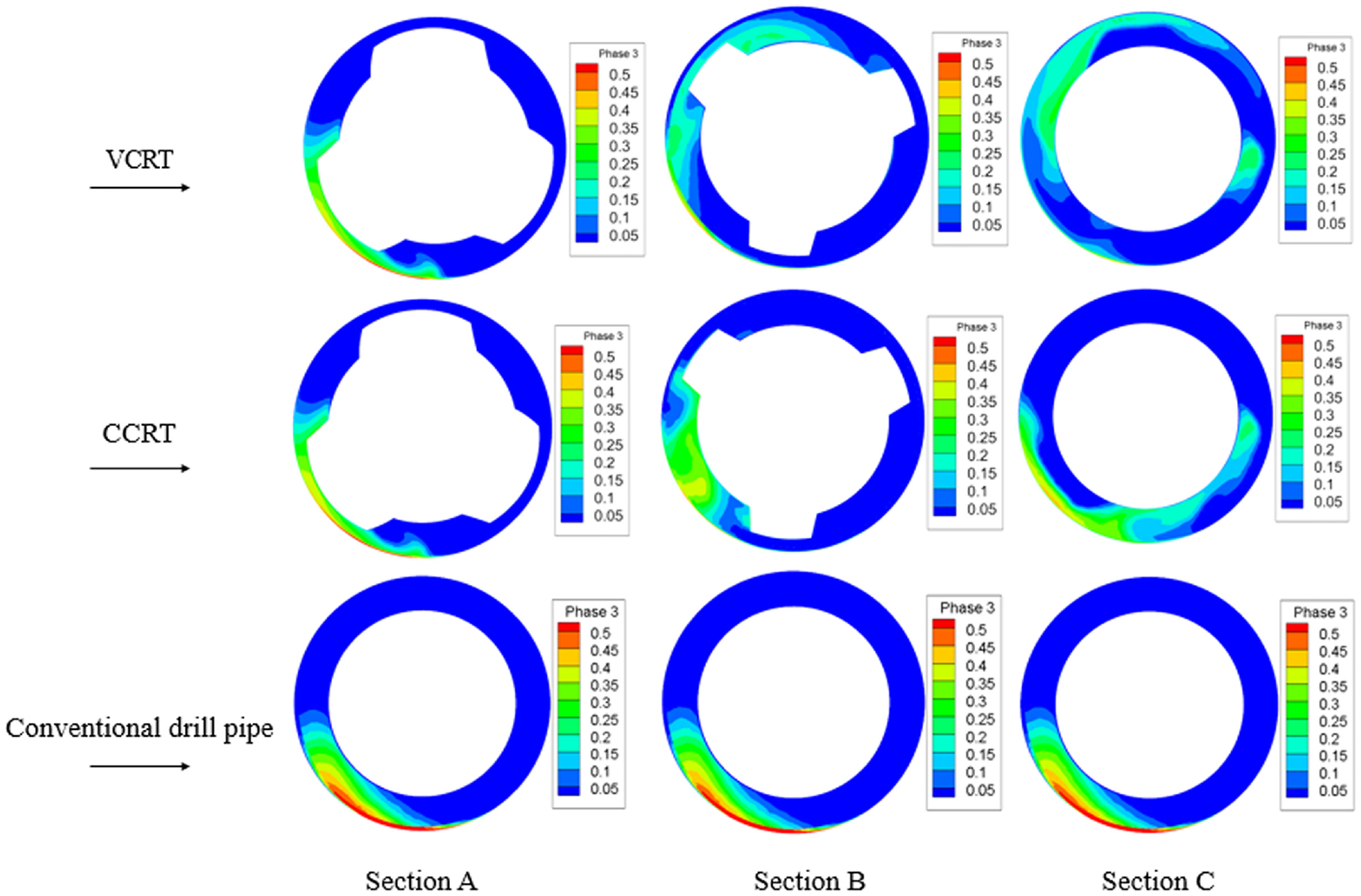
The cuttings distribution of the three tools in section (a–c) in sliding drilling at 0.42 s.
It can be seen from Figure 8 that the cuttings removal effect of VCRT and CCRT is obviously better than that of conventional drill pipe. In order to deeply explore the cuttings removal effect of VCRT, two critical paths, line 1 and line 2, were taken out to observe the cuttings migration. Where line 1 is a path through the inlet and outlet at the bottom of the model. Line 2 is a path from the inlet 1.0 m, Z-axis direction 0–25 mm, and the path lines are shown as Figure 7.
Figure 9(a) shows that the cuttings volume fraction at position 1 (as shown in Figure 7) under the action of VCRT is similar to that of CCRT. However, under the action of the rotating arris structures, the volume fraction of cuttings at position 2 (as shown in Figure 7) under the action of VCRT is significantly less than that of CCRT. As for the position 3 (as shown in Figure 7), the cuttings volume fraction under the action of VCRT is still less than that of CCRT. The total cuttings volume fraction is obtained by integrating the cuttings volume fraction over a distance of 0–1.4 m, and the total cuttings volume fraction under the action of VCRT is about 26% lower than that of CCRT.

Volume fraction curve of cuttings at line 1, 2 of the two tools in sliding drilling at 0.42 s: (a) cuttings volume fraction curve on line 1 and (b) cuttings volume fraction curve on line 2.
The cuttings volume fraction curves at line 2 (Figure 9(b), when sliding drilling 0.42 s) indicate that VCRT has a smaller cuttings volume fraction than the CCRT. The total cuttings volume fraction under the action of CCRT is 4 times higher than that of VCRT. The reason for this phenomenon is that the drilling fluid flowing through the rotating edge is enhanced after the action of the rotating arris structures of VCRT, the cuttings volume fraction under the action of VCRT at the same position is significantly lower than that of CCRT.
Rotary drilling condition
Figure 10 shows that the volume fraction of cuttings under the action of CCRT at section A, B, and C are similar to that of CCRT. During rotary drilling, the special structure on the CCRT rotates with drill pipe, which can effectively clean up the cuttings, thus the volume fraction of cuttings greatly reduced. However, the cuttings under the action of VCRT are more distributed on the higher side of the annulus, this is due to the higher rotational speed (180 r/min) of the rotating arris structures, which can generate higher energy to throw cuttings from the lower side of the wellbore into the annulus, therefore the removal effect of VCRT is still stronger than CCRT. As for the conventional drill pipe, Figure 10 shows that the cuttings still deposit on the lower side of annulus, the removal effect is significantly worse than the other two tools. Although the cuttings removal efficiency of conventional drill pipe improved due to the rotation of drill string, the improvement effect is limited.

The cuttings distribution of the three tools in section (a–c) in rotary drilling at 0.42 s.
It can be seen from Figure 10 that the removal efficiency of VCRT and CCRT is ideal during rotary drilling. Therefore, this paper mainly discusses the removal efficiency difference between VCRT and conventional drill pipe, and same as slide drilling, line 1 and line 2, were taken out to observe the cuttings migration.
It can be seen from Figure 11(a) that due to the rotation of the drilling string, the volume fraction of cuttings at the bottom are both pretty small compare to the sliding condition. At position 1 and position 3, the volume fraction of cuttings under the action of VCRT close to 0, significantly less than conventional drill pipe. The internal turbine of VCRT drives the external rotating arris structures to rotate under the hydraulic drive of the drilling fluid. And its speed is faster than that of the drill string. As a result, the cuttings volume fraction peak position under the action of VCRT is different from that of the conventional drill pipe and the value is close to that of the conventional drill pipe. The total cuttings volume fraction under the action of VCRT is about 78% lower than that of CCRT.
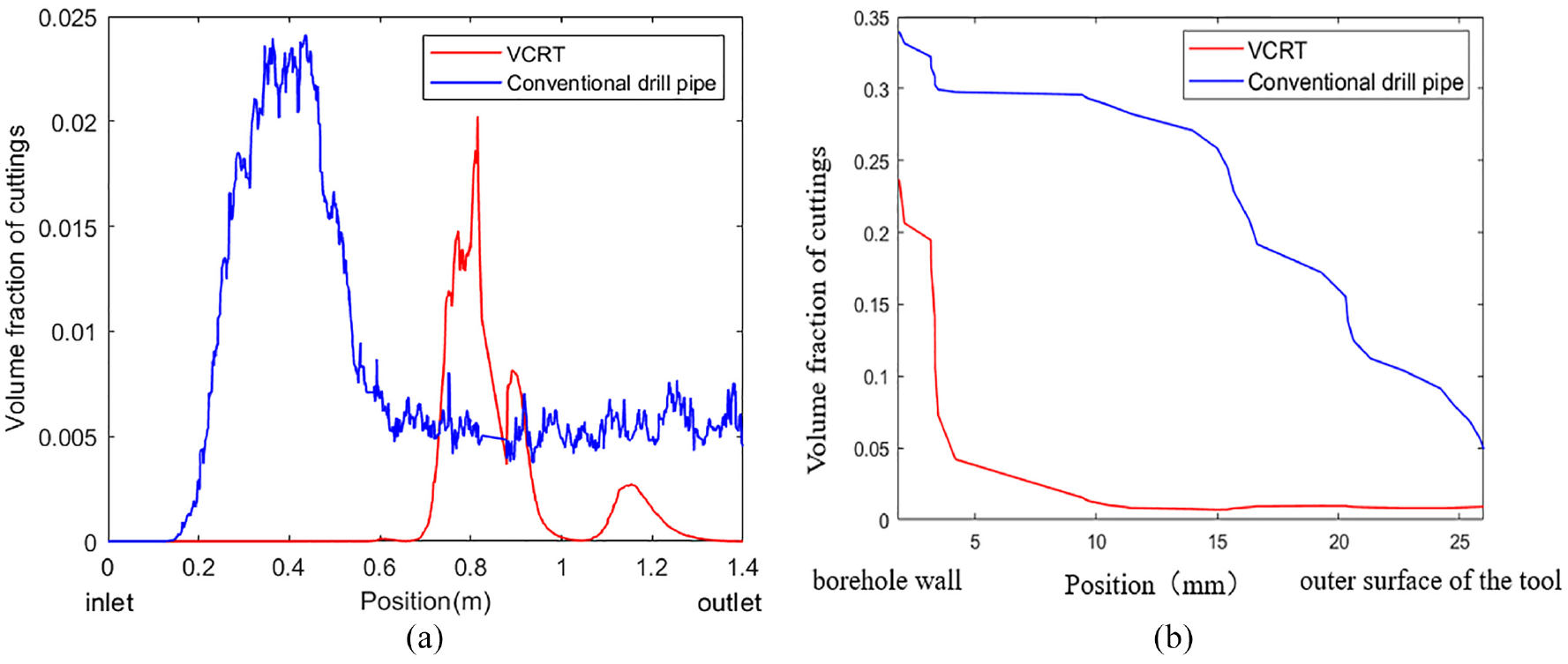
Volume fraction curve of cuttings at line 1, 2 of the two tools in rotary drilling at 0.42 s: (a) cuttings volume fraction curve on line 1 and (b) cuttings volume fraction curve on line 2.
The cuttings volume fraction curves at line 2 (Figure 11(b), when sliding drilling 0.42 s) indicate that the volume fraction of cuttings under the action of conventional drill pipe is significantly higher than that of VCRT. This is because the drill pipe surface of conventional drill pipe does not have any special structure, even if the drill string rotates, the energy generated is far less than that of VCRT, thus the removal efficiency is also very different. The cuttings distribution trend of VCRT is similar to that of sliding drilling, but volume fraction is less than sliding drilling, which indicates that rotation of drill string can improve cuttings removal efficiency of VCRT.
The distribution of cuttings in annulus changes with time under the action of different tools
In order to further explore the migration law of cuttings under the action of VCRT, this paper selects section B to observe the distribution of cuttings within a period of time. Analysis the difference of the cuttings distribution at section B under the action of VCRT, CCRT and conventional drill pipe under rotary drilling and sliding drilling conditions.
Figure 12 shows that at 0 s, the cuttings under the action of the three tools are all distributed on the lower side of the wellbore. As time flows, the cuttings on the lower side of the wellbore under the action of VCRT are reduced mostly, followed by CCRT, and the worst is the conventional drill pipe. At 0.42 s, the cuttings are significantly reduced under the action of VCRT, and most of the cuttings are distributed on the higher side of the wellbore, while CCRT and conventional drill string still have a certain amount of cuttings distributed on the lower side of the wellbore. The rotating arris structures of VCRT agitate the cuttings at the bottom of the borehole and carry them into the higher side of the annulus, than the cuttings can be expelled with the drilling fluid to achieve good cleaning effect.

The distribution of cuttings of the three tools at different times in section B during sliding drilling.
Figure 13 shows that during rotary drilling, the cuttings removal efficiency under the action of VCRT is still significantly better than that of conventional drill pipe. Compared with the sliding drilling (as shown in Figure 12), due to the rotation of the drill string, the cuttings under the action of the VCRT are more distributed in the annulus, indicating that the rotation of the drill string can enhance the cuttings removal ability of VCRT.
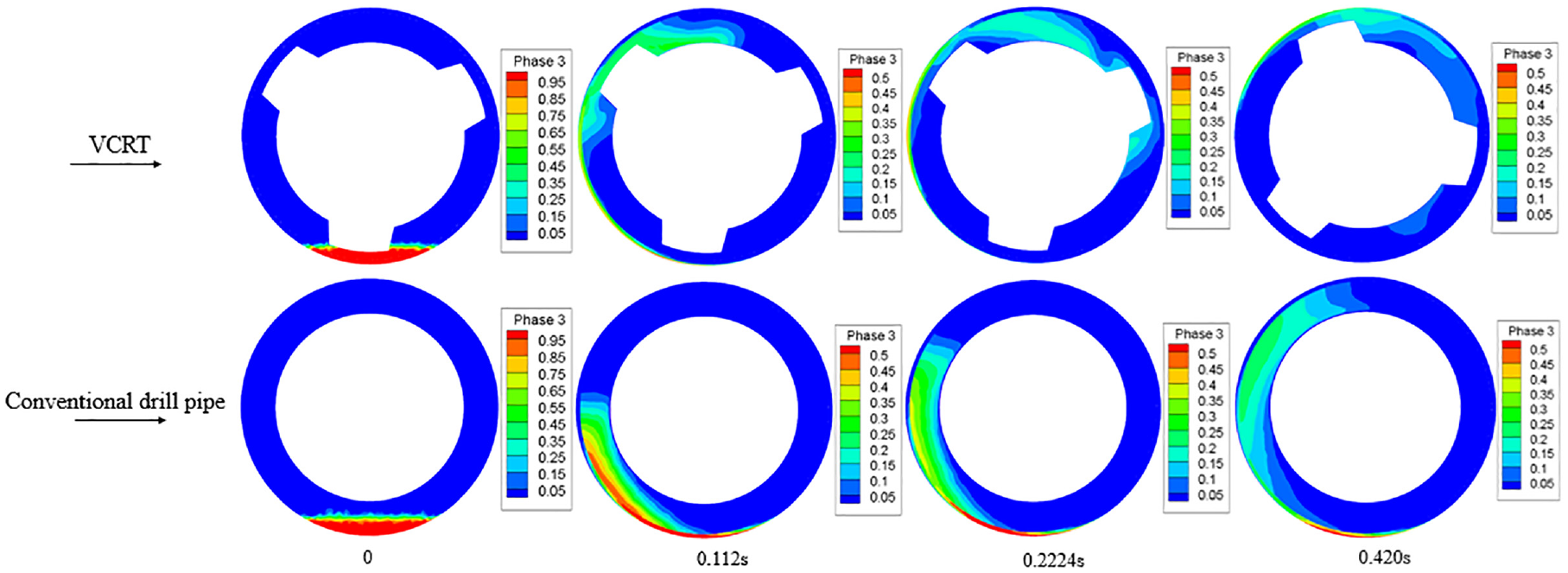
The distribution of cuttings of the two tools at different times in section B during rotary drilling.
When the time is 0.588 s, there are still a certain quantity of cuttings distributed at the bottom under the action of conventional drill pipe, while the cuttings under the action of VCRT are less distributed. Because of the rotation of the drill pipe, the conventional drill pipe can also bring the cuttings from the bottom into the higher side of the annulus under the action of the rotary drill pipe, but the effect is limited.
The facet average of volume fraction of cuttings on a surface (
Figure 14 shows the cuttings that passing through section B under the action of VCRT, the conventional drill pipe and CCRT in a certain period of time. During sliding drilling, the average cuttings volume fraction that passing through section B under the action of VCRT is 20% higher than that of the conventional drill pipe, and 15% higher than that of CCRT.

The average cuttings volume fraction curve of section B: (a) sliding drilling cuttings volume fraction curve and (b) rotary drilling cuttings volume fraction curve.
During rotary drilling, the cuttings passing through section B under the action of VCRT and conventional drill pipe are both increased, but the amount of cuttings passing through section B is still significantly higher than conventional drill pipe under the action of VCRT. The average cuttings volume fraction that passing through section B under the action of VCRT is 23% higher than that of conventional drill pipe.
Discussion
The advantage of VCRT compared with CCRT is that it can effectively destroy the cuttings bed in sliding drilling, thus the following discussion is carried out under the sliding condition. The pressure drop in the annulus flow field under the action of VCRT is 0.20 MPa. Tables 1 and 2 show the distribution of cuttings at different times on the same line under the sliding drilling condition. Line 1 and line 2 are both located on the lower side of the annulus, and the cuttings are deposited on the lower side of the annulus in the initial state (as shown in Figure 6). The fewer the cuttings content on the lower side of the annulus, the better the cleaning effect of the borehole.
Table 4 shows that the average cuttings volume fraction under the action of VCRT on line 1 is less than that of CCRT at any time. At 0.42 s, the average cuttings volume fraction under the action of VCRT on line 1 is about 26% lower than that of CCRT.
Average cuttings volume fraction at different times in line 1.

Figure 10(a) shows the distribution of the cuttings: at position 2(as shown in Figure 15), the volume fraction of the cuttings under the action of VCRT is close to 0, which is much smaller than that of CCRT. The cuttings volume fraction of VCRT is also smaller than that of CCRT at position 3(as shown in Figure 15). This is because the rotation of the rotating arris structures throws the cuttings from the lower side of the annulus into the higher side, therefore the cuttings on the line 1 are greatly reduced. In addition, the rotation of the rotating arris structures causes changes in the flow field, resulting in vortices. These vortices have changed the flow characteristics of the annulus flow field, and drilling fluid trends to flow from the lower side of the annulus to the higher side. This flow trend can transport cuttings from the lower side of the annulus to the higher side, therefore the cuttings under the action of VCRT are less than that of CCRT. It can be seen from Table 5 that the average cuttings volume fraction under the action of VCRT on line 2 is also smaller than that of CCRT at any time.

Section 1.0, 1.2, and 1.4 m away from the inlet.
Average cuttings volume fraction at different times in line 2.

Figure 16 shows the average cuttings volume fraction curve of the section 1.0, 1.2, and 1.4 m (as shown in Figure 15). By observing the cuttings passing through different sections at the same time, it can be found that: under the sliding drilling condition, the time-dependent variation of cuttings volume under the action of conventional drill pipe is approximately a decreasing function, the cuttings passing through the annular section are gradually reduced with time. Under the action of VCRT, the cuttings passing through the same section show a Gaussian distribution, and the cuttings that passing through the annular section first increase and then decrease.
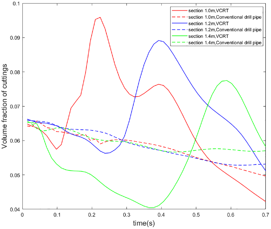
The average cuttings volume fraction curve of the section 1.0, 1.2, and 1.4 m.
Taking section1.0 m as an example, at the beginning, the flow of drilling fluid drives some cuttings in the initial state (as shown in Figure 6) to pass through section 1.0 m, but the quantity is small, and then the cuttings that enter the annulus due to the rotation of the rotating arris structures reach section 1.0 m, the cuttings passing through this section begin to increase. When most of the cuttings pass through the section, the subsequent cuttings decrease, and the cuttings passing through also decrease, so the overall trend is to increase first and then decrease. This distribution means that the cuttings are carried into the higher side of the annulus due to the rotation of the rotating arris structures, and the higher axial velocity of the higher side of the annulus is easier to carry the cuttings out of the wellbore. However, conventional drill pipe can only take away part of the cuttings on the surface of the cuttings bed by relying on the flow of drilling fluid, and cannot effectively destroy the cuttings bed, therefore the number of cuttings passing through the section shows a decreasing trend.
The average setting velocity of cuttings under the action of VCRT at section 1.4 m is about −0.00319 m/s (the gravity direction in the model is the negative direction along the Z-axis), while the average setting velocity of cuttings under the action conventional drill pipe is about −0.01269 m/s. The setting velocity of cuttings under the action of VCRT is much lower than that of conventional drill pipe, thus the cuttings can be migrated farther by the drilling fluid. Therefore, cuttings are difficult to accumulate under the action of the VCRT, and the cuttings removal efficiency under the action of VCRT is better.
Conclusion
The CFD method can better reveal the action mechanism of various cuttings removal tools. Based on the cuttings multiphase flow model, the changing law of the volume fraction of cuttings can be obtained, and the cuttings removal effect of various tools can be better evaluated.
During the sliding drilling condition, at 0.42 s, the average cuttings volume fraction under the action of VCRT on line 1 was 26% lower than that of CCRT; The average volume fraction of cuttings passing through section B is 15% higher than that of CCRT. During the sliding condition, the VCRT can better excavate and agitate the cuttings deposited on the lower side of the annulus, and throw them to the higher side to discharge with the drilling fluid.
During the rotary drilling condition, at 0.42 s, the average cuttings volume fraction under the action of VCRT on line 1 is 78% lower than that of conventional drill pipe; The average volume fraction of cuttings passing through the section B is 23% higher than that of conventional drill pipe. Under the rotary drilling condition, a large quantity of cuttings is still deposited on the lower side of the wellbore under the action of the conventional drill pipe (as shown in Figure 13), but VCRT can effectively remove the cuttings, the performance of VCRT is better.
VCRT uses the drilling fluid to drive the rotating arris structures, and the rotation of the rotating arris structures will throw the cuttings deposited on the lower side of the annulus into the higher side, therefore more cuttings can be discharged with the drilling fluid. VCRT can better destroy the cuttings bed deposited on the lower side of the borehole, and has the better borehole cleaning effect than CCRT and conventional drill pipe.
Footnotes
Handling Editor: Chenhui Liang
Declaration of conflicting interests
The author(s) declared no potential conflicts of interest with respect to the research, authorship, and/or publication of this article.
Funding
The author(s) disclosed receipt of the following financial support for the research, authorship, and/or publication of this article: This research was supported by the National Natural Science Foundation of China (52174003, U1663205, 51804194, 51704191) and Shanghai Leading Academic Discipline Project (S30106).