
Abstract
In this article, the authors establish the vehicle-track coupled model of smart railway track with rail-borne electromagnetic generator and conduct a symplectic analysis in frequency domain. A vehicle-track model considering vehicle traveling load is constructed, and the pseudo-excitation method is used. The frequency-dependent stiffness of rail pad is involved in the calculation model to get accurate results of rail natural frequency. The calculated results indicate that the smart railway track with electromagnetic generator will not affect the random vibration response of vehicle and bogie, but it could have certain influences on the wheelset and under-rail structure, especially the vibration response of rail, whose acceleration Power Spectrum Density difference reaches 18.6% with frequency shift of 54 Hz at basic frequency of 730.2 Hz, whereas the low frequency (below 200 Hz) rail vibration is not affected. The methods and results could serve as a guideline for the safety checking and dynamics calculation of smart railway track with rail-borne electromagnetic generator.
Keywords
Introduction
Motivation
Rail transport, as a means with a high level conveyance of passenger and cargo, plays an important role in our daily life. The building of rail infrastructure has experienced a sustainable growth in the past decade, especially in some developing countries. However, in remote areas, it is difficult to ensure power supply to rail-side monitoring equipment. It is therefore necessary to develop a new energy strategy to resort to renewable energy sources. Actually, Germany has already engaged in covering more than one-third of its annual 12 billion kilowatt-hour energy requirement for the railway network with renewable sources by 2020. 1
Review of the state of the art
The investigation of smart railway track is divided into two parts: (1) smart material and structure of the energy harvester and calculation of its electrical power generation capability, and (2) dynamic calculation of railway track with smart structures of energy harvester, including the dynamic response analysis and safety check. Studies of part 1—smart material and structures of energy harvesters in the railway industry are abound in literature and the smart structure can be categorized into two approaches—piezoelectric and electromagnetic device.
With regard to energy harvesters specified for transportation area, piezoelectric energy harvesting technology was widely investigated and application of piezoelectric pavement for highway traffic monitoring had been reported. 2 Nelson et al. 3 utilized both an inductive voice coil located near the rail and a piezoelectric device mounted under the rail for power harvesting for track monitor. Wang et al. 4 designed a mechanical power harvester with rack pinion, flywheel, and rotationally electromagnetic generator. Yuan et al. 5 conducted a comprehensive investigation of piezoelectric drum transducer for energy generation under loads of running urban vehicles. The test results showed that the rms output power is 0.081 mW with full load condition of Shanghai urban. The peak open-circuit voltage could be 50–70 V. Besides track-borne energy harvester, Pasquale et al. 6 designed a bogie-borne energy harvester with magnetic suspensions. The device with package of 150 × 125 × 95 mm 3 could generate 100 mW power output tested on a scaled roller rig, which simulated the freight train velocity of 80 km/h. In our previous study, we also introduced a new proposal of rail-borne electromagnetic energy harvester for powering the wireless sensor networks in the railway industry. 7
Although a myriad of energy harvesters were proposed and fabricated, only a few studies have discussed their influence on railroad vibration response. Yuan et al. 5 conducted a track-piezoelectric coupling analysis in time domain by Runge-Kutta method. In our previous study, we implemented track irregularity Power Spectrum Density (PSD) into the vehicle-track model and carried out calculation numerically by fast explicit integration methods.8,9 The abovementioned calculation methods use random samples of track irregularity PSD as excitation source, and the wheelset/track dynamic responses are solved by explicit integration method. The numerical integration methods in time domain could simulate the non-linear interaction force of wheelset/track, but it requires a huge calculation effort and it is hard to simulate the frequency-variant characteristics of rail pads. 10 Lu et al. 11 and Zhang et al. 12 adopted pseudo excitation method and symplectic mathematical scheme to build a vehicle-track coupled system model to analyze the random vibration of the coupled system. With symplectic mathematical scheme, only the track structure between adjacent sleepers needs to be modeled, which is subjected to the wheel–rail contact force, and the number of the degree of freedoms (DOFs) of track substructure is reduced to 16, which has improved the computational efficiency greatly. Zhao et al. 13 explored the efficiency method to study an infinitely long beam resting on a Kelvin foundation under moving random loads.
In a summary, there are few studies to consider the dynamic response and safety check of railway track with smart structures of energy generators, which sets the main motivations to undertake this study. The novel feature of the present investigation is the exploitation of symplectic mathematics scheme to calculate the dynamic response of railway track with smart electromagnetic energy generators.
Scope of paper
Based on the foregoing discussions, in this article, the authors utilize the pseudo excitation method and symplectic mathematics scheme to establish the symplectic analysis model of vehicle–track coupled system with electromagnetic energy generator. The proposed methods can analyze the random vibration of the vehicle–track coupled system with or without electromagnetic transducer. The efficiency of the calculations is greatly improved. Section “Introduction” of this article presents the review of the state-of-the-art of track-borne energy harvester in railway industry, which inspires the author to conduct this study. Section “Theory and modelling” presents the theory and modeling of symplectic mathematics methods to calculate the random vibration of the vehicle–track coupled system. Electromagnetic energy harvester is involved in the modeling to explore its influence on the dynamic responses of railway track. Section “Material and method of rail natural vibration test” presents the test methods for rail vibration characteristics. Results of both the natural frequency and random vibration analysis are shown in Section “Vibration characteristics of railway track with electromagnetic generator considering frequency-dependent stiffness of rail pad.” Finally, Section “Conclusion” gives a discussion on the necessity to implement the proposed methods for frequency response analysis of railway track system with electromagnetic generator and draws a conclusion.
Theory and modeling
Vehicle model
We built the vehicle model as a multi-body system with 10 DOFs as shown in Figure 1. The rail transit vehicle moves on the rail track at a constant speed of

Vehicle-track coupled system with electromagnetic generator.
Track model
The track substructure, which consists of three layers, that is, the rail, sleeper, and foundation, is assumed as an infinite Euler–Bernoulli beam supported on a discrete continuous elastic foundation.
For the railway track configuration with electromagnetic generator, the energy generator is rigidly connected to the rail web; it is neither connected to the wheelset nor to the rail sleeper, so we treat the parallel configuration as an added mass to the rail, and calculate the resultant change of the rail mass and rail moment of inertia. For this configuration, we assume the energy transducers were uniformly distributed at both sides of the rail, and thus, an additional moment of inertia, which stems from the structure profile of the energy transducers, is calculated by
The rail dynamics equation (Euler-Bernoulli beam assumption) reads

where

where
Therefore, the dynamic equation of railway track configuration with electromagnetic generator can be expressed as follows

Where
Sympletic model of railway track
The embedded sleeper track is the most commonly used track structure for subways, which can also be approximated as an infinite periodic structure (as shown in Figure 2). Therefore, the symplectic mathematical scheme can be adopted to establish the equations of motion of the track.
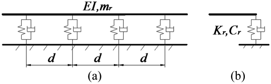
Schematic drawings of vertical whole structure and substructure of embedded sleeper tracks. (a) Whole structure and (b) substructure.
The track has four degrees of freedom, including the vertical and rotational degrees of freedom (zu1, θu1, zu2, and θu2) at each of its two interfaces of the beam. When the track is subjected to steady-state harmonic excitation, its equation of motion is expressed as

Where
For non-loaded substructure, the internal degree of freedom can be eliminated and the following equation can thus be obtained

Where ua, ub, pa, and pb are the response and nodal force vectors of the left- and right-hand interfaces of the ith substructure, respectively.
Equation (5) can be further transformed into a form of state space vector


Where S is the wave propagation transformation matrix μ is the propagation coefficient and eigenvalues of S, 1/μ is also the eigenvalue. In addition,
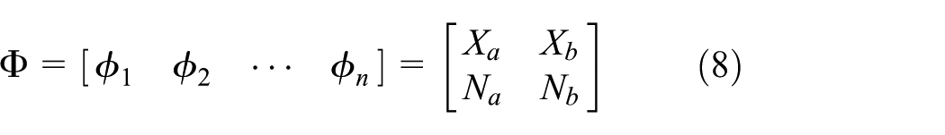
Pa and Pb are the dynamic stiffness matrices of the left- and right-hand interfaces of the substructure, which can be obtained from the characteristic vector matrix Φ

The degrees of freedom ua and ub in equation (5) be expressed in mode space as

Where a and b are coefficient vectors. By eliminating the internal degree of freedom ui in equation (5), the equation about the undetermined coefficients a and b can be expressed as below

Where
After getting the vectors a and b through the above equation, the required responses uk, pk at the kth interface of the periodic structure can be obtained in accordance with equation (10)


Where the subscripts l and r of uk, pk mean the left- and right-hand interfaces of the substructure; positive k is to the right of the loaded substructure and negative k is to its left, with the 0th interface being between the loaded substructure and the one to its right for k > 0 and to its left for k < 0.
Vehicle-track vertical coupled relations
Assuming that the vehicle and the track are connected through linear Hertz contact spring kh, 15 the wheel-rail force can be thus expressed as

Where uri is the displacement of the rail at the ith wheel-rail contact point, ri is the pseudo track irregularity, and uwi is the displacement of the ith wheelset.
For a single carriage, there are four contact points between wheel and rail. The left- and right-hand displacement vectors of the ith substructure, ul,i and ur,i, can be obtained as the sum of the responses caused by each of the four wheel-rail forces, that is

Consequently, the displacement of the rail at the contact point is expressed as

Furthermore, the equation of motion of the coupled vehicle-track system can be obtained

Where
Pseudo-excitation method for random vibration of the vehicle-track coupled system
Pseudo-excitation method is an accurate and efficient random vibration analysis method. The stationary random vibration analysis can be equivalent to the harmonic vibration analysis. The schematic of pseudo excitation can be expressed as the equation (17)


According to the traditional random vibration theories, when the linear system is subjected to the single-point stationary random excitation of the PSD Sxx, the response PSD of the system Suu can be obtained by multiplying Sxx by the frequency response function H(ω), that is shown in equation (17a); if the system is subjected to the unit harmonic load eiωt, its corresponding response will be shown in equation (17b); According to the nature of linear system, if

Based on the pseudo-excitation method, if the PSD of the track irregularity Sr(ω) is known, the pseudo-excitation vectors of the single carriage at the four vehicle-track contact points can be constructed

Where t2 = 2lt/v, t3 = 2lc/v, t4 = 2(lt + lc)/v, v is the vehicle speed. After the introduction of pseudo-excitation, the pseudo force vector

Thus, the pseudo response
Material and method of rail natural vibration test
Test method of rail natural vibration characteristics with GJ-III fastener
The accelerometers were placed on the top surface of rail at middle span. The excitation was generated by force-hammer along the longitudinal direction of track. The frequency response function was tested at each point. The distance between each point, the testing procedure, and methods refer to the international standard of EN 15461. 16 Test instruments include 24 bits analog–digital converter (INV3018CT, Dongfang Institute) with sampling frequency of 12,800 Hz, exciting-hammer (LC1302B) with measuring range of 50 kN and sensitivity of 0.105 mV/N, piezoelectric accelerometer (LC0102 T) with frequency range of 2–3000 Hz, sensitivity of 5 mV/g, and measuring range of 1000 g. Five measurements were conducted, and the average value was recorded. The test equipments and setup are illustrated in Figure 3.
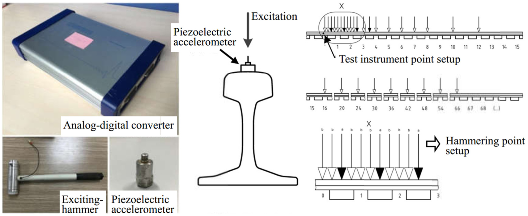
Test instrument and hammering point setup.
Test results of rail natural vibration characteristics with GJ-III fastener
The rail acceleration admittance is of significant importance to understand the natural vibration characteristics of rail. The tested acceleration admittance of rail original point is shown in Figure 4. The first order resonant mode of rail can be found. For railway track with GJ-III fastener, the rail natural frequency is 160.9 Hz. The amplitude of admittance increases gradually from 1 to 160.9 Hz, and then it decreases gradually and enters a flat and wavy area. The profile of wavy curve in the frequency range of 200–600 Hz is decided by the natural vibration characteristics of rail. We programmed a finite element analysis (FEA) script to calculate the natural frequency of rail with GJ-III fastener with frequency-dependency characteristics and the comparison of test and theoretical results can be found in Table 2 in the section “Natural frequency calculation of track considering frequency-dependent stiffness of rail pad.”
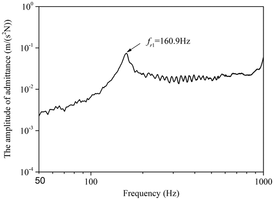
Vertical direct acceleration mobility amplitude curves of rails at mid-span.
Vibration characteristics of railway track with electromagnetic generator considering frequency-dependent stiffness of rail pad
The measurement and prediction of the dynamic mechanical performances of rail pads
It can be found that the stiffness of rail pad of different kinds of high polymer materials and the excitation frequency approximately form a linear relationship under the logarithmic coordinate system,17–19 as expressed in equation (21)

Where K0 is the low-frequency initial stiffness of the rail pad at the low excitation frequency f0 (usually f0 = 3∼5 Hz), k is the slope of the linear relationship between the rail pad stiffness and excitation frequency under the logarithmic coordinate system, representing the frequency-dependent extent (or frequent-dependent degree) of the rail pad stiffness. It can be easily seen from equation (21) that the relationship between the stiffness of rail pad of different materials and the excitation frequency mainly depends on its low-frequency initial stiffness K0 and its stiffness’ frequency-dependent extent k.
Figure 5 shows the frequency-dependent stiffness of the test pads in GJ-III fasteners within 1000 Hz and under 20 °C. It is clear that the actual dynamic mechanical parameters of rail pads are not supposed to be the frequency-independent and temperature-independent constants. Overall, the stiffness of rail pads increase with the decrease of temperatures or the increase of frequencies.

The frequency-dependent stiffness of GJ-III rail pad within 1000 Hz and under 20°C.
According to the experimental data, the linear slope for the changes in the stiffness of GJ-III rail pad with the frequency under the logarithmic coordinate system is all 0.131 under 20°C; in addition, the initial stiffness of GJ-III rail pad is 16 kN/mm under an excitation of 3–5 Hz.
Natural frequency calculation of track considering frequency-dependent stiffness of rail pad
For accurate calculation of random vibration response of railway track, we take the frequency-dependent stiffness of rail pad into consideration. Normally, the static stiffness of rail pad is used and the value is set to be a constant. In this article, instead of static stiffness, we use the frequency-dependent stiffness of rail pad, that means the rail pad stiffness Kr(fn) is a variable quantity, whose value is depended on the dynamic vibration frequency of rail. Thus, an iteration algorithm is developed, whose flow chart is shown in Figure 6.

Flow chart of algorithm of rail pad stiffness calculation.
Take the calculation of rail natural frequency for an instant. First, we assume an initial frequency f0, get the initial fastener stiffness Kr(f0) at this frequency, and then calculate the natural frequency f1 of rail. Next step is to make a judgment of f0 and f1, the criterion is the allowable numerical calculation error (in this case the error is set to be 0.1 Hz), if f1–f0 > 0.1 Hz, the iterative calculation goes on and the rail vibration frequency f2 is obtained based on the fastener stiffness of Kr(f1). After going through the nth iteration and meeting the judgment criterion, that is, fn– fn–1 < 0.1 Hz, we end the iteration. The final rail natural vibration frequency is set to be fn. We use the track structure with parameters listed in Table 1 and compare the results of test and calculation, the comparison is shown in Table 2.
Parameters of track model.

Comparison of rail natural frequency with constant or frequency-dependent stiffness of rail pad.

It is found that when we use the constant rail pad stiffness, the calculation results of rail natural frequency is 124.9 Hz. Compared to the test results, the difference reaches 36 Hz (22.4%), whereas if we use the frequency-dependent rail pad stiffness, the calculation results is 158.7 Hz, the difference is only 2.2 Hz. This difference mainly comes from the simplification of track model. The foundation is assumed to be a rigid body. Generally, we could realize more accurate calculation of rail vibration frequency by utilizing the frequency-dependent rail pad stiffness.
Natural frequency analysis of railway track with electromagnetic generator
As shown in Figure 1, the energy generator is rigidly connected to the rail web; it is neither connected to the wheelset nor to the rail sleeper, so we treat the parallel configuration as an added mass to the rail, and calculate the resultant change of the rail mass and rail moment of inertia. The mass of the energy transducers per meter is 15 kg and the additional moment of inertia is 145.4 cm4. The rail natural frequency up to 20th order is calculated for both the normal railway track and smart railway track, the above-mentioned frequency-dependent rail pad stiffness is also involved in the calculation.
As shown in Figure 7(a), the first order natural frequency of the steel rail of normal railway track is 158.7 Hz, whereas that of smart railway track is 142.1 Hz. This difference is due to change of rail vibration characteristics induced by the added mass and moment of inertia of electromagnetic generators. Figure 7(b) shows the difference in relation to the order. The higher the order, the larger the difference, and the relationship scales non-linearly with the order. Thus, the existence of electromagnetic generator will have a larger influence on the high-frequency component of rail vibration.

Natural frequency and its’ difference of steel rail with/without electromagnetic generator. (a) Natural frequency and (b) natural frequency difference.
Random vibration analysis of railway track with electromagnetic generator
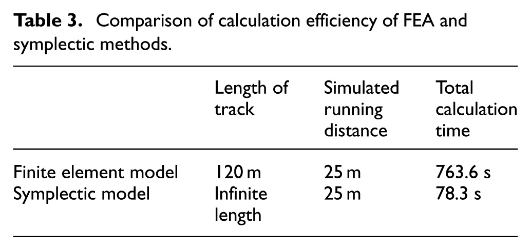
In order to ensure the accuracy, the numbers of DOFs of the track structure model with a limited length should be 200 at least when it is modeled by the finite element method. Compared with the FEA method, the symplectic mathematical scheme can model the track structure with unlimited length; furthermore, by unitizing the railway track between adjacent sleepers, the numbers of DOFs of each track substructure are reduced to 16. Therefore, the numbers of DOFs of the FEA model are 10 times more than the symplectic model, so that the symplectic model can greatly improve the computational efficiency. If the calculation model requires longer railway track length, the symplectic model possesses more advantage over the FEA counterpart. Thus, the symplectic method has much higher calculation efficiency than the finite element method. An example is analyzed to verify the efficiency improvement of the symplectic model by using the computer with the configuration of i7-4790 CPU and 16G RAM. The comparison of calculation efficiency of FEA and symplectic methods is shown in Table 3.
Comparison of calculation efficiency of FEA and symplectic methods.
Based on the natural frequency analysis, it is found that the difference between normal railway track and smart railway track is quite obvious. To further study the random vibration response of the two railway tracks, we use the Sympletic method and the vehicle-track coupled model. The vehicle parameters are listed in Table 4. America fifth grade track irregularity spectrum is added as the external excitation. Different track spectrum has different application condition, different range for vehicle velocity, and is suitable for different track line. Normally, for common track line, American AAR fifth grade track spectrum (vehicle velocity below 144 km/h) and AAR sixth grade track spectrum (vehicle velocity below 176 km/h) are widely used worldwide; for high-speed track line, German low disturbance track spectrum (vehicle velocity above 250 km/h) and German high disturbance track spectrum (vehicle velocity below 250 km/h) are widely used worldwide. This study is aimed at implementing the rail-borne electromagnetic energy generators into the common railway; therefore, the American AAR fifth grade track spectrum (vehicle velocity below 144 km/h) is used in this article.
Dynamic parameters of the metro vehicle.

According to the calculation results, the PSD of vehicle and bogie acceleration is nearly same for two railway tracks. The added electromagnetic generators would only have an influence on the wheelset and under-rail structures. As shown in Figure 8, for the normal railway track, the first order dominant frequency of wheelset acceleration PSD is 38.2 Hz with peak value of 1.031 m2/s4/Hz, whereas for the smart railway track, the peak value is 0.984 m2/s4/Hz. The difference is 4.56%, which is acceptable from the viewpoints of railway engineering. Thus, the existence of electromagnetic generator would not affect the running safety of rail transport vehicle.

PSD of wheelset acceleration with/without electromagnetic generator.
Figure 9 shows the PSD of rail acceleration of two railway tracks. It is observed that at the frequency range less than 200 Hz, the PSD profiles of two tracks are quite similar; however, when the frequency is larger than 200 Hz, the PSD variation is quite obvious. At the predominant frequency A, the corresponding rail acceleration peak values are 0.815 m2/s4/Hz (normal railway track) and 0.777 m2/s4/Hz (smart railway track). The percentage of peak value difference reaches 4.66% without basic frequency shift (41.6 Hz for both tracks). At the predominant frequency B, for normal railway track, the rail acceleration peak value is 0.720 m2/s4/Hz with frequency value of 730.2 Hz, whereas for smart railway track, the rail acceleration peak value is 0.844 m2/s4/Hz with frequency value of 676.2 Hz. The percentage reaches 17.2 with frequency shift of 54 Hz. The similar trend is also observed at predominant frequency C. So the rail-borne electromagnetic generator would change the predominant vibration frequency of rail, especially the high-frequency component.
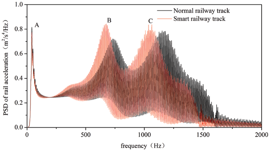
PSD of rail acceleration with/without electromagnetic generator.
Conclusion
We conducted natural frequency analysis and random vibration analysis of the railway track with/without electromagnetic generators. The pseudo excitation method and symplectic mathematics model were utilized to improve the calculation efficiency and get more accurate results in frequency-domain. The main findings were as follows: (1) the smart railway track with electromagnetic generator will not affect the random vibration response of vehicle and bogie, but it could have certain influences on the wheelset and under-rail structure; (2) the frequency-dependent stiffness of rail pad needs to be involved in the calculation model to get more accurate results of rail natural frequency; (3) the rail-borne electromagnetic generators could change the natural frequency of rail and the difference value scales non-linearly with the order; therefore, a safety check calculation (i.e. dynamic response calculation, ride safety and ride comfort check) is necessary for the railway engineers to implement the rail-borne electromagnetic generators; and (4) the rail-borne electromagnetic generator could have an influence on the vibration response of railway track at different frequency range. Its influence to the vehicle and bogie is negligible, but could change the PSD peak value of rail acceleration at frequency range larger than 200 Hz. The high-frequency component of natural frequency would be shifted obviously. The results in this article could be helpful to the dynamics evaluation of smart railway track with rail-borne electromagnetic generator.
Footnotes
Handling Editor: ZW Zhong
Declaration of conflicting interests
The author(s) declared no potential conflicts of interest with respect to the research, authorship, and/or publication of this article.
Funding
The author(s) disclosed receipt of the following financial support for the research, authorship, and/or publication of this article: This work was supported by the National Science Fund for Distinguished Young Scholars under Contract 51425804.