
Abstract
This study proposes a linear electromagnetic generator that can harvest vibration energy from a transformer and supply electricity to a monitoring system. The sensor system delivers voltage and electricity information from a transformer and it usually requires a battery that must be replaced periodically. These result in high costs, working hours, and manpower, and workers may sometimes face very dangerous situations, especially when a transformer is located in a mountainous area or an elevated position that cannot be accessed easily. The transformer vibrates at a frequency of approximately 50 Hz or higher. In this study, a linear electromagnetic generator was designed to analyze and harvest this vibration energy. A prototype was produced and its performance was tested, which showed that more than 100 mW of electricity could be produced, which is the minimum amount required for the electricity analysis system.
Introduction
Studies on energy harvesting technology are being carried out to help address environmental and energy depletion issues. 1 Energy can be harvested from wasted sources such as solar thermal energy, vibration energy, and pressure energy, which can be converted into usable electricity. 2 Mechanical vibration has high energy density, it is not affected by climate conditions, and it is not constrained by space. Vibration energy can be harvested from ambient micro-vibrations, from body activities, and from mechanical equipment. 3 It is not influenced by the environment since a device can be built without being exposed to the outside, so it can be applied as a plug-in type device, unlike other harvesting systems. 4 The vibration energy harvesting systems are electrostatic, electromagnetic, piezoelectric, and so on. Electrostatic harvesting systems are advantageous for miniaturization, but they have low energy conversion efficiency. Systems that use piezoelectric ceramics are expensive, and it is fragile. 5 Electromagnetic harvesting systems have lower production cost, longer lifetime, and higher power efficiency.6,7 Electromagnetic methods include linear generators and rotary generators. In a rotary-type generator, linear vibration motion is converted into rotary motion using screws, chains, or gears. This increases the weight of the generator and complicates the structure and maintenance, in contrast to a linear generator. 8
Park et al. 9 carried out a study to charge a mobile phone battery by harvesting and applying dormant vibration energy to a linear generator. Kim and Choi 10 carried out a feasibility study for a self-powered wireless emergency call button using an electromagnetic energy harvesting mechanism. Lim et al. 11 developed a tubular electromagnetic linear generator. Linear electromagnetic generators could be useful for harvesting vibration energy in various industries.
Figure 1 shows a common transformer which vibrates at a frequency of 60 Hz with displacement of approximately ±1.5 mm. A wireless load monitoring system which is circled in the figure helps prevent failures by detecting abnormalities. 12 The monitoring system measures the voltage, current, and temperature of the transformer and delivers information to an administrator.

Transformer and wireless load monitoring system.
An electric battery is essential for supplying electricity to the monitoring. However, it requires periodic management for charging and replacement on a 2-year basis. If the transformer is located in a mountainous area or in an elevated position where people cannot access it easily, the maintenance requires high costs, working hours, and manpower, and workers may sometimes face very dangerous situations. Therefore, an electromagnetic linear generator was studied to harvest the vibration energy and address these issues. The generator was analyzed through MAXWELL, a commercial electromagnetic finite element analysis program, and a prototype was produced and tested to verify the performance.
Analysis of vibration characteristics
The linear electromagnetic generation system for harvesting vibration energy is shown in Figure 2(a). The system is attached to the top of the transformer. It can be modeled by assuming the vibration is due to excitation of the bottom base of the generator, as shown in Figure 2(b). The vibration can be expressed mathematically using equation (1)

where y(t) and x(t) indicate the vibration displacement of the transformer and the displacement of the generator armature, respectively. y(t) can be expressed as a sine wave using

where ζ is the damping ratio of the generator and r is ratio of the base excitation frequency
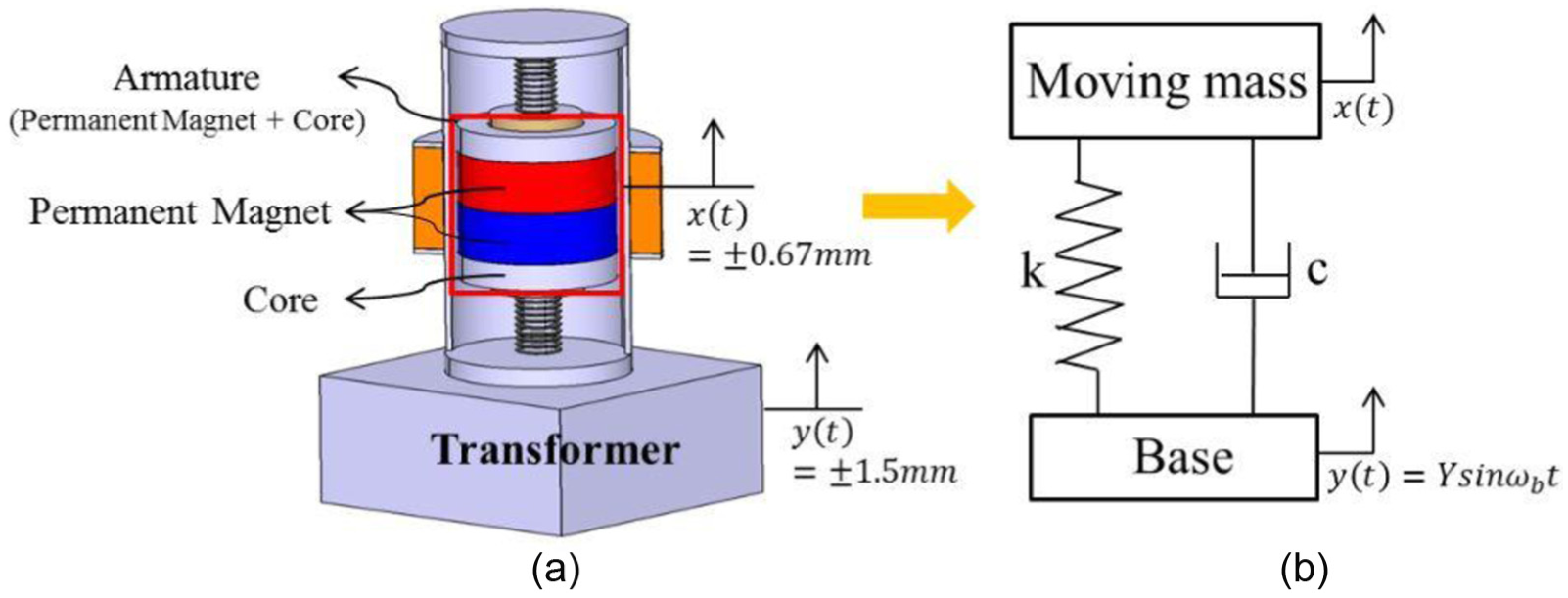
Schematic diagram of vibration model of linear generator system.
The bottom amplitude displacement is very small, so the generator should be designed using the energy amplification effects based on the resonance phenomenon according to the base excitation frequency, the armature mass of the generator, and the natural frequency. Therefore, the maximum displacement of the armature for the optimal natural frequency and base excitation displacement can be calculated according to the base excitation frequency using equation (2), 13 as shown in Figure 3. Figure 3 shows the displacement transmissibility, which is the ratio of the maximum displacement to the input displacement according to each natural frequency change. The displacement transmissibility is highest when the bottom base excitation frequency is 60 Hz and the natural frequency is approximately 60 Hz. The maximum displacement of the armature at this point is ±0.67 mm. It is possible to maximize the output of the generator by inducing the resonance phenomenon using this information.

Bottom base excitation frequency and displacement transmissibility according to natural frequency.
Structure and principle of linear electromagnetic generator
Figure 4 shows a schematic diagram of structure of the proposed generator, which consists of an armature, stator, and case. The armature consists of a permanent magnet, core, and shaft, while the stator consists of electromagnetic coils. A neodymium–ferrite (Nd-Fe) magnet is used for the permanent magnet. Non-magnetic stainless steel is used for the shaft, and steel 1010 is used for the core. Tension and compression springs were used to apply the resonance phenomenon to the armature.

The structure of proposed linear electromagnetic generator.
When the transformer’s base excitation frequency of 60 Hz is applied to the generator, the armature moves up and down in the axial direction. Electromotive force is induced in the stator coil and generates electrical energy. As shown in Figure 5, a magnetic flux lines are produced as a result of linear reciprocating motion of the permanent magnet as a result of the vibration. The magnetic flux generated by the magnet flows in the core and passes through the electromagnetic coil terminal of the stator through an air gap between the armature and the stator. The generated electromotive force can be expressed as follows according to Faraday’s law
where N is the number of coil turns, Φ is the flux passing for each electromagnetic coil turn during time t, and

Magnetic flux lines produced by the permanent magnets.
Electromagnetic characteristics of the linear generator in the axial direction
The generator’s length is limited shape to 130 mm, and the diameter is limited to 80 mm. The length and diameter of the generator were designed to be 60 and 50 mm, respectively. According to these standards, a linear electromagnetic generator model was selected based on the ratio of the size of the permanent magnet to that of the core. MAXWELL was used to analyze the electromagnetic characteristics of the selected model, which are expressed based on axial symmetry modeling, as shown in Figure 6. Because the shaft located at the innermost part of the generator is a non-magnetic body, it is excluded from the modeling for electromagnetic analysis.
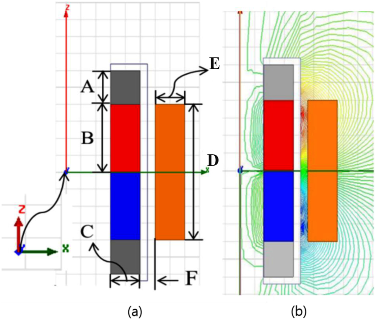
(a) Basic simulation modeling in an axial-symmetric view and (b) flux distribution plot.
A maximum armature displacement of ±0.67 mm and a base excitation frequency of 60 Hz were applied as the input conditions based on the analysis of the vibration characteristics. Table 1 shows the model specifications, and Table 2 shows the materials of each component used in MAXWELL. Two magnets and two cores were used, each with a thickness of 10 mm. The height of the magnet was 20 mm, and that of the core was 10 mm. AWG 26 with a diameter of 0.405 mm was used for the coil, which had 1870 single-phase turns. The simulation was carried out using transient analysis to check the generation output of the linear generator over time passed with a stop time of 0.3 s and a time step of 0.5 ms. Figure 7 shows the induced voltage and current of the linear generator from MAXWELL. The average voltage and current generated were 6.0021 V and 0.080 A, respectively, and the generation output was approximately 500 mW. Figure 6(b) shows the flux distribution plot.
Axial-symmetric view linear electromagnetic generator properties in MAXWELL.

Properties of linear electromagnetic generator.


Transient analysis results of generation (induced voltage and current).
Production and experiment of linear electromagnetic generator
For the experimental verification, the linear electromagnetic generator was produced as shown in Figure 8 and Table 3. The figure also shows the produced armature, while Figure 9 shows the experimental process.

The prototype of linear electromagnetic generator (left) and armature (right).
Linear electromagnetic generator specifications.


The experimental process.
After attaching the generator to the fixture jig, an acceleration sensor was installed near the armature to record the displacement data of the armature. Then, we connected a function generator, a base excitation amplifier, and exciter equipped with a linear electromagnetic generator. An experiment was carried out by applying driving current with frequency of 60 Hz to check the displacement data of the armature of the linear electromagnetic generator. The voltage and electric power on each resistance were also measured when adjusting the amplifier driving current, and the acceleration data from the sensor were monitored using a PC and a data acquisition (DAQ) device. The acceleration data were converted to the displacement using MATLAB.
The base excitation vibration input control method in the simulation was different from that in the experiment. In the electromagnetic simulation, the analysis was carried out using a ±0.67-mm input displacement to the armature, but in the actual experiment, the armature displacement was not controlled. Therefore, currents of 2, 4, and 6 A (below the maximum permitted current of 7 A for the amplifier) were applied to the exciter at 60 Hz for the experiment. Figure 10 shows the generated voltage results and the displacement results. The voltage increases with the load resistance, while the armature displacement shows a significantly less change with different load resistances.

(a) Voltage generated (V) and (b) displacement generated (mm) with different loads and amplifier driving currents.
Table 4 shows the correlation results between the generated voltage and displacement for each driving current, and Figure 11 shows a graph of the results. The voltage changes linearly with respect to the driving current closely. Figure 12 shows the expected power (W) for an armature displacement of ±0.67 mm. As a result of the experiment with increasing load resistance, the voltage per unit displacement was measured. Based on this, we calculated the generated voltage and current according to the predicted displacement and predicted that the maximum power would be generated at a load resistance of 75 Ω. The maximum electricity output occurred at a load resistance of 75 Ω. The voltage and current were approximately 4.6 V and 0.0613 A, and the electricity output was approximately 300 mW.
Voltage per unit displacement generated according to the load at different amplifier driving currents (V/mm).


Voltage per unit displacement generated according to the load at different amplifier driving currents (V/mm).

Expected power (W) for displacement of 0.67 mm.
The expected electricity output exceeded the minimum of 100 mW required for the wireless load monitoring system of the transformer. Therefore, the generator could replace the battery for the monitoring system.
Conclusion
In this study, a linear electromagnetic generator was designed to drive the wireless load monitoring system for a transformer by harvesting the vibration energy. To simulate the generation of electric power, the dynamic finite element analysis using commercial software “MAXWELL” was performed. A prototype was produced and tested, which verified that the generator could produce more than 100 mW of electricity. This is the minimum value to operate the monitoring system. In result, it shows the possibility that our proposed energy harvesting system can replace the battery system and supply electricity to a monitoring system.
Footnotes
Handling Editor: Yucheng Liu
Author note
Author Seong Jin Cho is now affiliated to Korea Textile Machinery Convergence Research Institute, Gyeongsan, Republic of Korea.
Declaration of conflicting interests
The author(s) declared no potential conflicts of interest with respect to the research, authorship, and/or publication of this article.
Funding
The author(s) disclosed receipt of the following financial support for the research, authorship, and/or publication of this article: This work was supported by Civil-Military Technology Cooperation Program (no. 16-CM-EN-17) funded by the Defense Acquisition Program Administration and the Ministry of Trade, Industry and Energy in Korea.