
Abstract
The electromagnetic piezoelectric hybrid-driven 3-degree-of-freedom motor is a new multi-degree-of-freedom motor. To further analyze the torque characteristics of the electromagnetic piezoelectric hybrid-drive 3-degree-of-freedom motor. First, the principle and basic structure of the hybrid-drive motor are introduced, and the displacement and pressure distribution of the stator–rotor contact surface are obtained by analytical method. Based on this, the torque model of the piezoelectric stator-drive motor is obtained. Then, the air-gap magnetic field model of the permanent magnet rotor is obtained by analytical method, and the electromagnetic stator-torque model is obtained. Finally, the torque model of the electromagnetic piezoelectric hybrid-drive 3-degree-of-freedom motor is established by vector synthesis. The effects of piezoelectric stator mounting position angle, stator–rotor contact materials, and preload on motor torque are analyzed by simulation. The advantages of electromagnetic piezoelectric hybrid drive are analyzed, and the rationality of the model is preliminarily verified. It lays the foundation for further optimization design and performance improvement of electromagnetic piezoelectric hybrid-drive 3-degree-of-freedom motor.
Keywords
Introduction
With the development of modern intelligent industry, the requirements for precision of multi-degree-of-freedom drive devices are constantly increasing. The multi-degree-of-freedom motion actuator composed of the traditional single-degree-of-freedom motor has complicated mechanical structure, 1 large volume, and low positioning control precision, which cannot meet the requirements of intelligent precision driving. The multi-degree-of-freedom motor has a simple structure and high integration, which can be applied in a precise drive system. 2 There are two main driving methods for multiple free motors: piezoelectric and electromagnetic.
Piezoelectric-driven multi-degree-of-freedom ultrasonic motors were first proposed by the Tokyo University of Agriculture and Technology. 3 In recent years, international scholars have conducted extensive research on ultrasonic multi-degree-of-freedom motors. 4 Yamagata University proposed a small cylindrical 3-degree-of-freedom motor. The hollow cylinder of the stator of the motor acts to conduct amplifying vibration, and the vibration is provided by a piezoelectric layer below the cylinder. Muroran Institute of Technology proposed a disk-type multi-degree-of-freedom ultrasonic motor and conducted in-depth comparative studies on different bearing lubrication methods.4,5 Zhejiang University conducts in-depth research on mathematical models and motion control of traveling wave multi-degree-of-freedom motors.6,7 Shanghai University proposed a sandwich motor of more than 10 degrees of freedom 8 and established a fixed-rotor contact model. Nanjing University of Aeronautics and Astronautics proposed a circular standing wave multi-degree-of-freedom motor 9 and reviewed the current problems in the design of this type of motor. Harbin Institute of Technology proposed a sandwich ultrasonic multi-degree-of-freedom hybrid-drive motor, 10 and they produced a prototype and analyzed the characteristics of the variable excitation mode of multi-degree-of-freedom ultrasonic motor. Southeast University has designed a multi-degree-of-freedom ultrasonic motor with a double stator clamping structure, 11 which has improved drive torque and improved output performance and stability. Piezoelectric-driven motors have received the widest attention because of their high power density, stable efficiency at very small dimensions, high positioning accuracy, fast response, and power-off interlocking. 12 However, since the piezoelectric-driven motor is based on friction transmission, its performance and life depend on the performance of the friction interface. 13
Electromagnetic-drive multi-degree-of-freedom motors were developed first by the Soviets. In recent years, international scholars have done a lot of research on electromagnetically driven multi-degree-of-freedom motors. For example, Tianjin University applied Halnach array structure to spherical multi-degree-of-freedom motors to improve the complexity of motor magnetic field distribution and motor performance. 14 Hefei University of Technology proposed a new spherical multi-degree-of-freedom stepper motor 15 and analyzed the magnetic field, torque, and mechanical model of the motor in detail. On the basis of summarizing the advantages and disadvantages of the predecessors, Hebei University of Science and Technology proposed a new 3-degree-of-freedom motor with double-layer coil rotor single-layer permanent magnet structure and optimized the motor structure by particle swarm optimization. 16 Hanyang University proposed a new 3-degree-of-freedom motor with a double-excitation source of sandwich structure. 17 This motor greatly reduces the cost of the motor because the rotor no longer uses permanent magnets. Nanyang Technological University proposed a spherical motor for conformal printing, 18 which greatly improves the reliability of the printing system. Although the multi-degree-of-freedom motor has high mechanical integration and simple transmission, the structure of electromagnetic-drive multi-degree-of-freedom motor is relatively complicated, and the magnetic field is difficult to control. The improvement of control and positioning accuracy is always a difficult point. The torque output produced by the rotor is very difficult and the loss is large during torque output. At present, the structure of electromagnetic-drive multi-degree-of-freedom motor is more complicated, and the reliability still falls short of the required state. 19
The development of electromagnetic piezoelectric hybrid-drive motors has gradually become a development trend.20–23 Piezoelectric-drive multi-degree-of-freedom motor is immune to external electromagnetic interference, which provides the possibility of electromagnetic piezoelectric hybrid-drive multi-degree-of-freedom motor development. The electromagnetic-drive multi-degree-of-freedom motor24,25 has relatively complicated structure, the magnetic field is difficult to control, the control and positioning accuracy is low, the torque output by the rotor is difficult, and the torque loss is large. Piezoelectric-drive multi-degree-of-freedom motors have problems such as low lifetime and performance affected by fixed-rotor friction materials. The multi-degree-of-freedom motor with electromagnetic drive is suitable for working at high speed and low torque, but its structure is complicated and it is difficult to achieve miniaturization, and the control-positioning accuracy is low, which is not suitable for precise work. Multi-degree-of-freedom motor with piezoelectric drive is compact in structure, flexible in design, easy to realize miniaturization, self-locking, fast response, and free from external electromagnetic interference. It is especially suitable for low-speed and high-torque applications; but the life of piezoelectric-driven motor is short, and it is not suitable for continuous operation. Therefore, combining the electromagnetic drive and the piezoelectric drive can not only avoid the problems of the two drive modes but also improve the speed, accuracy, and torque of the motor.
In order to further study the electromagnetic piezoelectric hybrid-drive multi-degree-of-freedom motor, a 3-degree-of-freedom electromagnetic piezoelectric hybrid-drive motor was modeled and analyzed. First, the piezoelectric-driven stator–rotor contact model and the electromagnetically driven air-gap magnetic field model are established by combining the piezoelectric drive and electromagnetic-drive principle. Then the torque model of the electromagnetic piezoelectric hybrid-drive 3-degree-of-freedom motor is established by vector synthesis method. The simulation software analyzes the influence of piezoelectric-drive stator position, stator–rotor contact material, and preload on motor torque and verifies the rationality of the analysis results by finite element analysis.
Electromagnetic piezoelectric hybrid-driven 3-degree-of-freedom motor structure and operation mechanism
The electromagnetic piezoelectric hybrid-drive 3-degree-of-freedom motor is mainly composed of four stators and one rotor. The structure diagram is shown in Figure 1. As shown in Figure 2, the stator is composed of three piezoelectric stators (No. 1 stator, No. 2 stator, and No. 3 stator) and one electromagnetically driven stator (No. 4 stator) in Figure 3. The piezoelectric ceramic piece on the piezoelectric stator is applied with an alternating voltage. This voltage phase difference is 90°, the frequency is the same, and the amplitude is the same. Due to the inverse effect principle of piezoelectric ceramics, two-phase standing waves are reflected. The two-phase standing wave amplitudes are equal and the phase difference in time and space is 90°. The two-phase standing waves are superimposed to form a circular traveling wave. At this time, the rotor of the motor rotates in the tangential direction of the particle surface of the stator surface, and the direction of rotation of the rotor is opposite to the direction of the traveling wave.
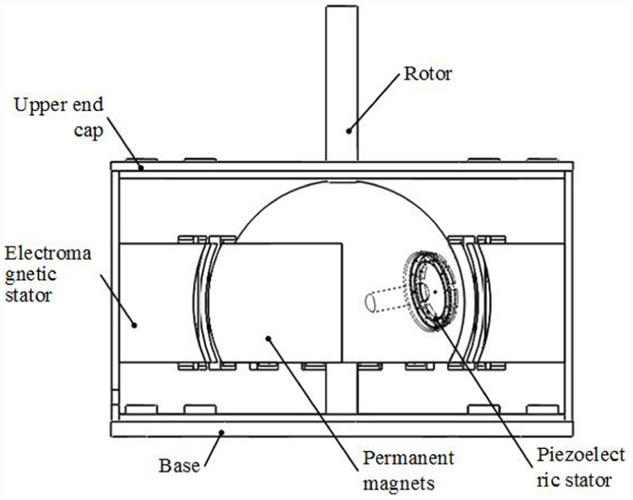
Electromagnetic piezoelectric hybrid-drive 3-degree-of-freedom motor overall structure diagram.
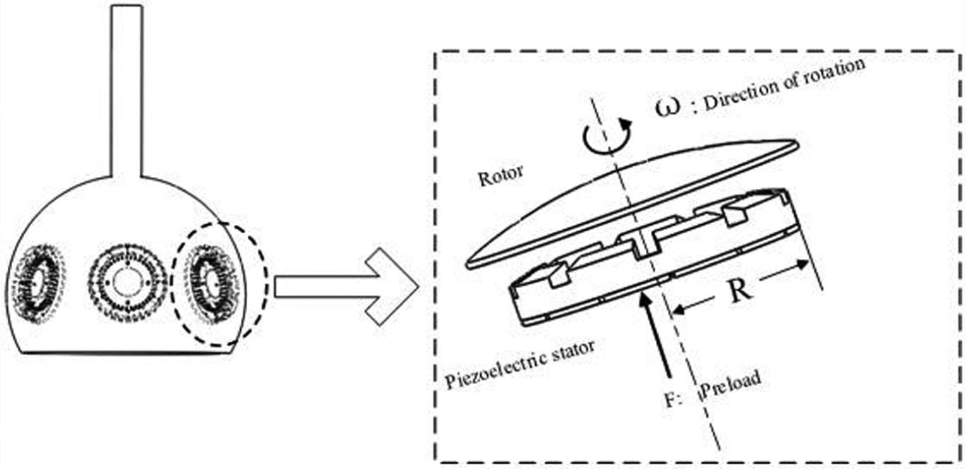
Electromagnetic piezoelectric hybrid-drive 3-degree-of-freedom motor rotor and piezoelectric stator.

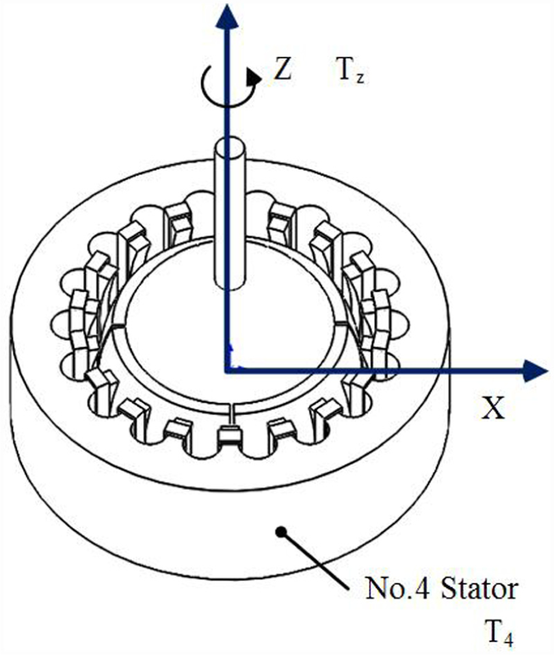
Electromagnetic piezoelectric hybrid-drive 3-degree-of-freedom motor rotor and electromagnetic stator.
As shown in Figure 3, the spherical rotor surface is mounted with four permanent magnets. The electromagnetic-drive torque is generated by the interaction of the surface-mounted permanent magnets and the fourth stator. Through the coordinated control of the four stators and the two drive modes being sequential in this process, the motor can finally achieve 3-degree-of-freedom motion.
Piezoelectric stator-drive model
Stator traveling wave generation
The piezoelectric ceramic piece on the piezoelectric stator is applied with an alternating voltage. This voltage phase difference is 90°, the frequency is the same, and the amplitude is the same. Due to the inverse effect principle of piezoelectric ceramics, two-phase standing waves are reflected. The two-phase standing wave amplitudes are equal and the phase difference in time and space is 90°. The two-phase standing waves are superimposed to form a circular traveling wave. The inverse piezoelectric effect can be expressed by the piezoelectric equation 26


where e is the piezoelectric constant matrix (eT is the transposition of the piezoelectric constant matrix),


u is a position function of the point on the ceramic piece, and (x, y, z) is the position vector. There is no displacement of the ceramic piece in the Y-axis direction, only the force in the X1 direction is considered, and the electric field obtained by the ceramic piece is a uniform electric field. The ceramic sheets are polarized in the thickness direction, and the length of the ceramic sheets is greater than the radial width.
From the above assumptions
The above assumptions are brought into the piezoelectric equation to obtain

According to Newton’s second law, the equation of motion of ceramic sheets can be known

Equation (7) is brought into equation (8) to obtain
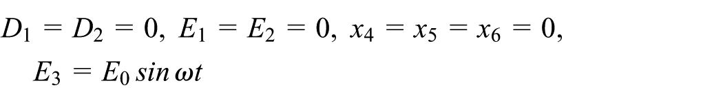
The electric field component E3 is a uniform electric field

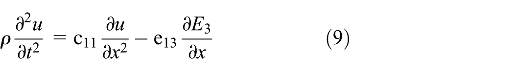
Therefore, the piezoelectric wave equation is

where ρ is the density of the piezoelectric ceramic.
The special solution for obtaining the traveling wave equation is


where,
Equations (12) and (13) are brought into equation (7):
The traveling wave is obtained by superposition of the two-phase standing waves of a and b

Contact model of stator and rotor
It is assumed that the contact layer of the stator is an elastomer. The stator is displaced to the maximum displacement in the Z-axis direction when the stator is in contact. The stator is a rigid body and does not displace, and the friction between the stator and rotor is ignored. The stator–rotor contact is equivalent to the contact of the parabolic indenter with the contact layer (elastomer) as shown in Figure 4.

Stator and rotor contact diagram.
The preload applied by each stator is F, then the one-dimensional pre-stress experienced by each peak is
The waveform of the stator waveform at a certain time is

The stator–rotor contact zone displacement function can be set to

where d0 is an unknown constant.
When the stator friction is neglected, the stator and rotor boundary shear force is 0:
The normal stress distribution of the fixed rotor is:
According to the balance of the stator and rotor

a is half of the fixed-rotor contact distance for one wavelength of the stator.
When the stator’s normal contact force

Suppose the rigid body does not shift, so B" = 0.
So we get

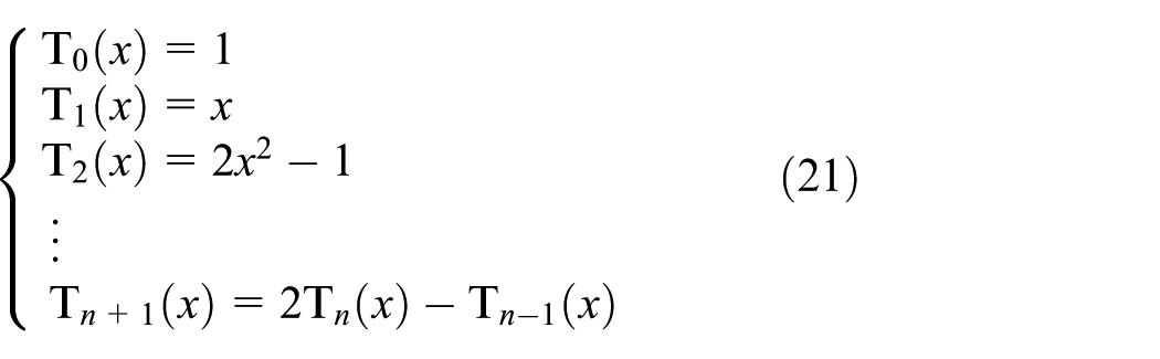
The method of solving the first type of Freehold equation by the Chebyshev polynomial of Popov28,29


Form obtained

The contact pressure of the contact point of the contact zone is 0, so,
Equation (24) is taken into equation (17) to

Equation (24) is taken into equation (19) to

Therefore,
The stator-torque contact surface force distribution equation

The displacement equation of the stator–rotor contact surface

Friction model of stator and rotor
According to the Coulomb friction model30,31


where μd is the dynamic friction factor; μs is the static friction factor; vrel is the relative sliding speed of the stator; p(x) is the normal pressure, and F is the tangential thrust
In the contact region within the normal contact pressure, on the cut synthetic rotor thrust F
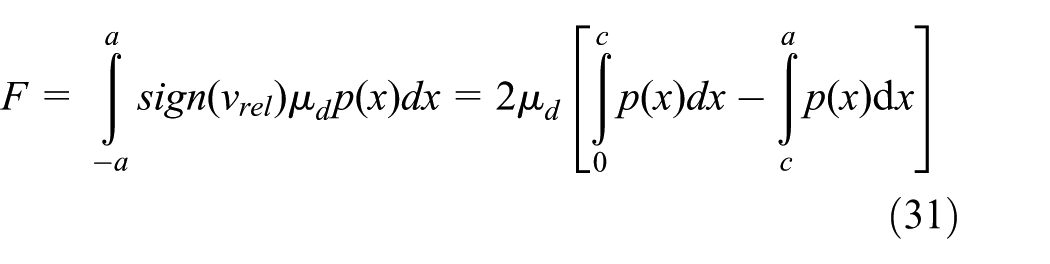
where c is the point at which the relative sliding speed of the rotor is zero. When c = a, the maximum tangential thrust is obtained, and the single stator obtains the maximum output torque

where n is the number of traveling wave peaks; R1 is the radius of the stator rotor contact surface; j = 1, 2, 3.
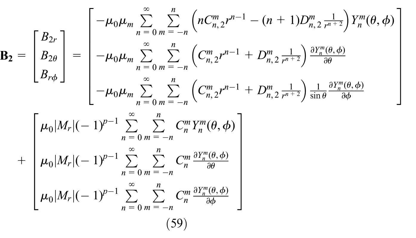
Electromagnetic stator-drive model
Electromagnetic-drive stator–rotor air-gap magnetic field
According to the boundary condition of the magnetic medium, the magnetic field generated by the rotor permanent magnet can be divided into three parts

where
According to the principle of the motor, there is no current excitation in the rotor area, which can be obtained

The negative value of the gradient of the scalar magnetic position can represent the magnetic field strength

According to the structure of the motor, the permanent magnets are symmetrically distributed, so

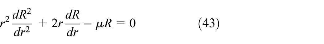
Then the scalar magnetic positions of the three regions satisfy the Laplace equation

According to the structure of the permanent magnet, the residual magnetization of the motor in the spherical coordinate system can be expressed as

where p (p = 1, 2, 3, 4) is the permanent magnet number, L is the total number of permanent magnets.
In the spherical coordinate system, the magnetic position V can be expressed as a function of the spatial point (r, θ, φ), that is, V(r, θ, φ), where r is the coordinate radial distance of the point, θ is the latitude, and φ is longitude.
The Laplace equation of the magnetic position V can be expressed as the Laplace equation of the scalar magnetic position

Assume

Equation (40) is divided by R(r) Y(θ, φ)

Equation (41) is multiplied by r2 on both sides, and the variables are adjusted

where μ is the parameter introduced by the separation variable method.
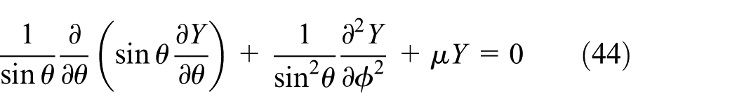
The spherical harmonic equation further separates the variables, assume
where λ is the parameter introduced by the separation variable method.
Obtained by simultaneous equations (43), (45), and (46)

where
The permanent magnet rotor boundary conditions are:
The magnetic mark is 0 at infinity

so,
The magnetic mark is finite at the origin of the magnetic field

so,
The tangential and radial components of the magnetic induction at the interface of the medium are continuous


The expression of magnetic induction in spherical coordinates is
The radial component of the residual magnetization is expressed in the form of a spherical harmonic function. Any single-valued and finite function

where,


The special solution of the specific magnetic mark can be obtained by the above boundary conditions. The air-gap magnetic-tight fundamental wave of the motor can be obtained by calculation

Electromagnetic coil–drive torque model
The magnetic field generated by the energized coil (radial length q (mm)) interacts with the magnetic field generated by the permanent magnet, which produces the Lorentz force of the interaction (the force is macroscopically expressed as Ampere); the electromagnetic force generated by a certain coil dl micro-element that can be obtained by the law32,33

The electromagnetic torque generated by the dl micro-element

The torque generated by the single coil is obtained by integrating the torque micro-element on a single coil


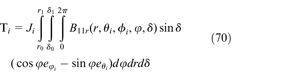
where Ji is the surface current density of the coil, and ro r1 is the coil radial length,

Stator and rotor section equivalent diagram.
Since the integral operation of the equation (65) cannot be directly performed in the spherical coordinate system, it is necessary to convert the components in the spherical coordinate system to the Cartesian coordinate system

After converting each component of the spherical coordinate system into a Cartesian coordinate system, the expression of each unit of the coil


where r is the distance from the point on the coil boundary to the center of the sphere. θi is the projection of the coil boundary point below the spherical coordinate θ axis. φi is the projection of the coil boundary point on the spherical coordinate φ axis. δ is the angle between the line from the point on the coil to the center of the ball and the line from the center of the coil to the center of the ball.

Electromagnetic stator projected on the rotor.
In the local rectangular coordinate system, the resulting derivative is converted to dl element:
The electromagnetic torque can be obtained by combining the above formulas
The torque decomposition can be used to decompose the electromagnetic torque to obtain the single-coil rotation torque.
Rotational torque

where i is the coil number (i = 1, 2, 3,…,18)
As shown in Figure 7, the total torque produced by all coils is calculated from the distribution of the coils


Electromagnetic stator equatorial plane distribution map.
Electromagnetic piezoelectric hybrid-drive 3-degree-of-freedom motor torque synthesis
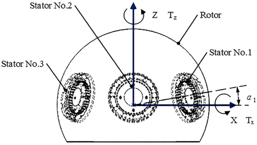
The line passing through the No. 2 stator is defined as the Y-axis, the axis perpendicular to the Y-axis is the X-axis, and the line perpendicular to the X-Y plane and passing through the origin is defined as the Z axis. The three traveling wave stators are mounted at 120° and are α1° to the X-Y plane as shown in Figures 8–10. The electromagnetically driven stator is mounted outside the spherical rotor to provide torque to the rotor about the Z-axis. Therefore, the hybrid-drive motor realizes 3-degree-of-freedom motion by multi-degree-of-freedom motion through four stator synthesis. Tx, Ty, and Tz are vectors of the rotor rotating around the X, Y, and Z axes, respectively. The torque of the 3-degree-of-freedom motor is T, and the torque vectors T1, T2, T3, and T4 of the four stators are combined to obtain34,35


Piezoelectric stator–rotor structure top view.
Front view of the piezoelectric stator–rotor structure.
Top view of the electromagnetic stator–rotor structure.
Numerical simulation and analysis
It can be seen from the formula (71) that the yaw torque TX is obtained by the torque synthesis generated by the No.1 and No.2 stators. The deflection torque Ty is obtained by the torque synthesis generated by the No.1, No.2, and No.3 stators. The rotation torque Tz is obtained by torque synthesis of the No.1, No.2, No.3, and No.4 stators. The magnitude of the torque of the 3-degree-of-freedom motor driven by the electromagnetic piezoelectric hybrid is affected by the mounting position angle a1 of the No.2 stator of the No.1 stator of the No.1 stator. According to the stator material parameters of Tables 1 and 2, the torque characteristics were analyzed by MATLAB.
Piezoelectric stator structure parameters.

Friction material parameters of piezoelectric stator and rotor contact layer.

PTFE: polytetrafluoroethylene.
Piezoelectric ceramic piezoelectric constant matrix:
Clamping dielectric constant matrix:
Piezoelectric ceramic short-circuit stiffness matrix:
Influence of materials on torque characteristics of 3-degree-of-freedom motor driven by electromagnetic piezoelectric hybrid drive
Influence of material on deflection torque characteristics
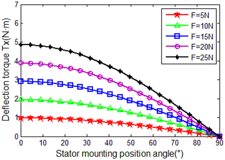
In order to further analyze the torque of the electromagnetic piezoelectric hybrid-drive 3-degree-of-freedom motor, the maximum output deflection torque characteristics of different preload, different contact materials and piezoelectric stator mounting position angle rotors were calculated using MATLAB, as shown in Figures 11–16. When the piezoelectric stator mounting position angle is constant, the deflection torque TX increases as the preload F increases. At this time, the maximum deflection torque can reach 4.871 Nm; when the preload is constant, the deflection torque Tx of the motor decreases as the installation angle of the piezoelectric stator increases; when the installation angle of the rotor is constant, the deflection torque Ty is pre-adjusted. The pressure F increases as the pressure increases. At this time, the maximum yaw torque can reach 5.625 Nm; when the preload is constant, the yaw torque Ty decreases with the increase of the piezoelectric stator mounting position angle; when the material is the same, the yaw torque Tx is greater than the yaw torque Ty.

Maximum output deflection torque Tx when the rotor contact is nylon.

Maximum output deflection torque Tx when the rotor contact is PTFE.
Maximum output deflection torque Tx when the rotor contact is steel.

Maximum output deflection torque Ty when the rotor contact is nylon.

Maximum output deflection torque Ty when the rotor contact is PTFE.

Maximum output deflection torque Ty when the rotor contact is steel.
Influence of material on rotation torque
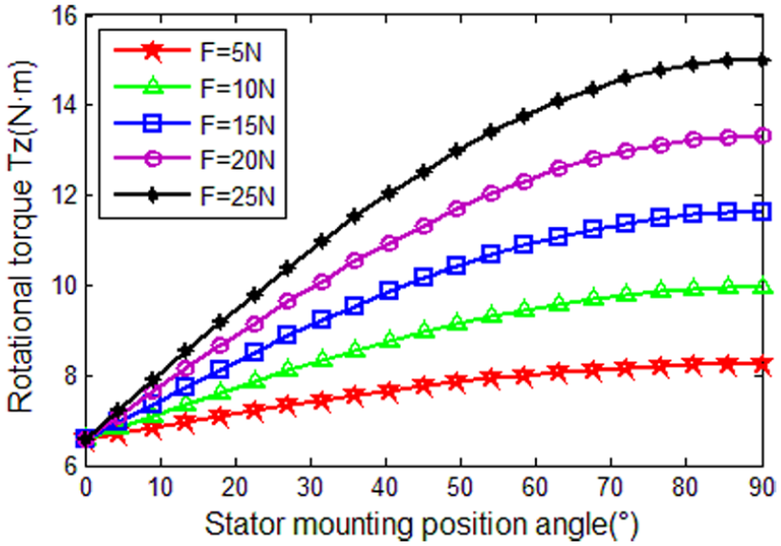
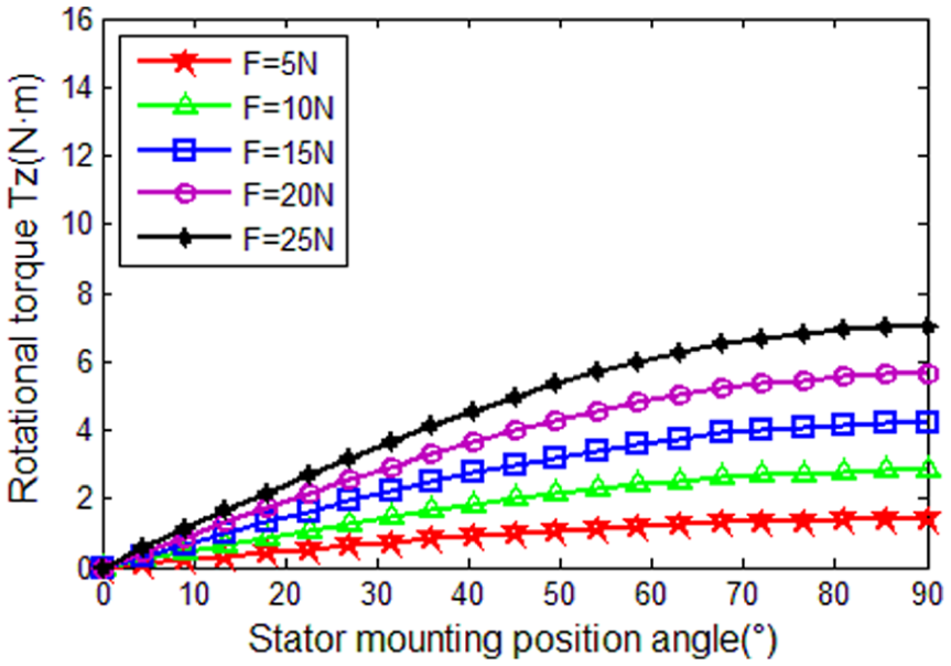
In order to further analyze the torque of the electromagnetic piezoelectric hybrid-drive 3-degree-of-freedom motor, the maximum output rotation torque characteristics of the rotor with different preload, different contact materials and stator installation position angle are calculated using MATLAB, as shown in Figures 17–19. When the rotor-mounting position angle is constant, the rotation torque Tz increases as the preload F increases. When the preload is constant, the rotation torque Tz increases as the angular position of the piezoelectric stator is increased. The maximum rotation torque reaches 15.1 Nm.

Maximum output rotation torque Tz when the rotor contact is PTFE.
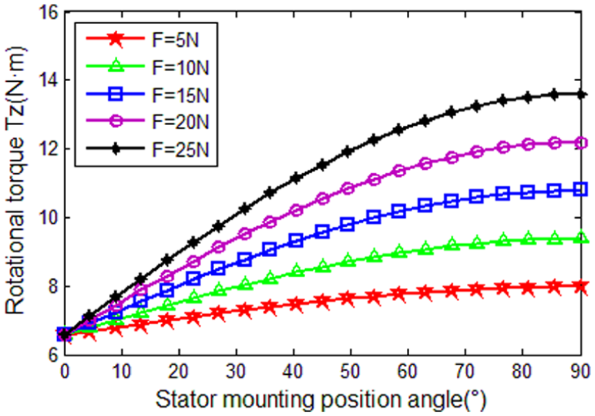
Maximum output rotation torque Tz when the rotor contact is nylon.
Maximum output rotation torque Tz when the rotor contact is steel.
Influence of driving mode on rotation torque
When the stator contact material is nylon, the rotation torque of the motor when piezoelectric drive is obtained (as shown in Figure 20) and the rotation torque of the motor when electromagnetic piezoelectric hybrid drive are performed (Figure 21). By comparison, it can be seen that the maximum rotational torque of the piezoelectric single drive can reach 7.03 Nm, and the maximum rotational torque of the electromagnetic piezoelectric hybrid-drive motor can reach 13.6 Nm. In addition, the piezoelectric-drive motor has a compact structure, flexible design, easy miniaturization, self-locking, and fast response. The motor with electromagnetic drive has a complicated structure, and it is difficult to achieve miniaturization, and it has low control-positioning accuracy, and it is difficult to be applied in a precision working place. It is found by calculation that the combination of electromagnetic-drive and piezoelectric drive increases the torque of the motor.
Output rotation torque Tz when the piezoelectric stator is separately driven to contact nylon.
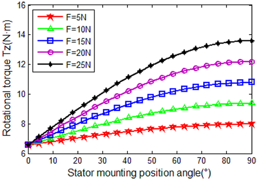
Electromagnetic piezoelectric hybrid-drive contact is nylon when output rotation torque Tz.
The reliability of the motor is improved by a combination of two drive methods. In order to further verify the rationality of the analytical calculation, the influence of the piezoelectric stator position angle on the rotation torque was verified by the finite element software for the nylon material at the preload of 25 N, as shown in Figure 22.
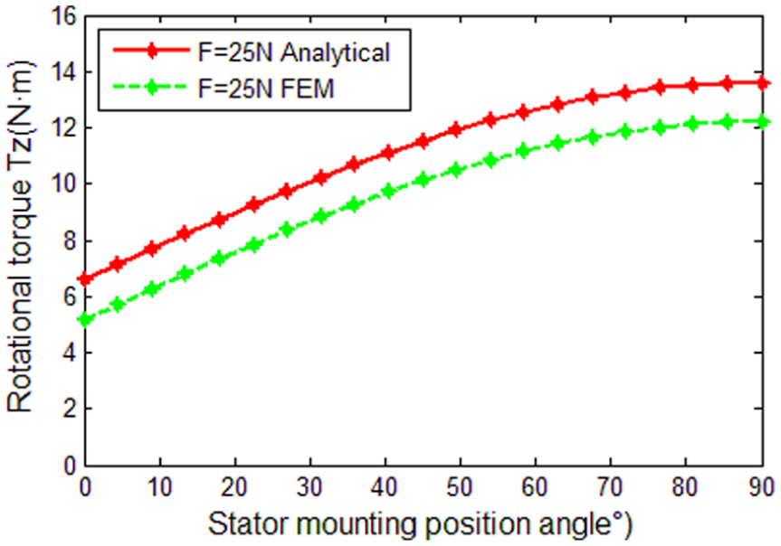
Comparison of analytic method and finite element method when the rotor contact is nylon.
Conclusion
First, the principle and basic structure of the hybrid-drive motor are introduced and the displacement and pressure distribution of the stator–rotor contact surface are obtained by analytical method. Based on this, the torque model of the piezoelectric stator-drive motor is obtained. Then, the air-gap magnetic field model of the permanent magnet rotor is obtained by analytical method, and the electromagnetic stator-torque model is obtained. Finally, the torque model of the electromagnetic piezoelectric hybrid-drive 3-degree-of-freedom motor is established by vector synthesis.
The influence of different contact layer materials on the contact pressure distribution of the stator and rotor and the contact distance on the torque characteristics were analyzed by MATLAB. It can be seen from the analysis that the larger the position angle of the No.1, No.2, and No.3 stators, the larger the deflection torque. The larger the position angle of the No.1 and No.2 piezoelectric stators and No.3 stator, the smaller the self-rotation torque. In order to achieve a higher precision in the output reliability of the motor, the positional angle of the No.1, No.2, and No.3 stators can not be 0°. When the position angle of the No.1, No.2, and No.3 stators is 0, the motor rotates only for the electromagnetically driven rotor, which greatly reduces the precision of the rotor drive. By comparing and analyzing the piezoelectric driving motor and the electromagnetic piezoelectric hybrid driving motor, it is known that the combination of piezoelectric and electromagnetic driving not only improves the torque of the motor but also improves the reliability of the motor. It provides a theoretical basis for the design and torque optimization and improvement of the electromagnetic piezoelectric hybrid-drive 3-degree-of-freedom motor.
Footnotes
Handling Editor: Xiaodong Sun
Declaration of conflicting interests
The author(s) declared no potential conflicts of interest with respect to the research, authorship, and/or publication of this article.
Funding
The author(s) disclosed receipt of the following financial support for the research, authorship, and/or publication of this article: This work was supported by the National Natural Science Foundation of China (grant no.: 51577048, 51877070, and 51637001), the Natural Science Foundation of Hebei Province of China (grant no.: E2018208155), the Overseas Students Science and Technology Activities Funding Project of Hebei Province (grant no.: C2015003044), the Hebei Industrial Technology Research Institute of Additive Manufacturing (Hebei University of Science and Technology) open projects funding, the National Engineering Laboratory of Energy-saving Motor & Control Technique, Anhui University (grant no.: KFKT201804), and Key project of science and technology research in Hebei provincial colleges and universities (grant no.: ZD2018228).