
Abstract
In this article, a novel flexure-based 3-degree-of-freedom elliptical micro/nano-positioning motion stage was developed to obtain translation motions along the x, y, and z directions with high working bandwidth. The stage was configurations with a XYZ vertical motion to ensure the crosstalk between each axis is small enough. The motion stage was driven by three piezoelectric actuators. The corresponding working principles and stiffness modeling were detailed in this article. In addition, experimental testing was conducted to investigate the performances of the motion stage. The obtained strokes in x, y, and z directions are 10.39, 15.43, and 15.55 μm, respectively. The response rise time for each axis is within 10 ms, and the maximum crosstalk all within 1.2% ensured the rapid tracking can be achieved.
Introduction
Piezoelectrically actuated compliant mechanisms have been widely used in many fields like ultra-precision machining,1–3 nano-positioning,4–7 and biomechanical engineering 8 due to their many advantages such as high precision, structural variability, and so on. The demand for a compliant micro/nano-positioning stage with a large workspace and high precision is increasing. A huge number of efforts have been devoted to the design, modeling, and control of the positioning stages with multi degrees of freedom (DOFs) to satisfy the requirements of complicated operations, especially the 3-DOF elliptical micro/nano-positioning motion stage.
From the view of structure configurations, the 3-DOF elliptical micro/nano-positioning motion stage can be classified into two sorts, one is of serial flexure hinges and the other one is of parallel flexure hinges. 9 Various types of flexure hinges have been studied. Circular flexure hinges were one of the most widely used flexure hinges and to be studied because of its precise in rotation. Paros and Weisbord 10 formulated the design equations of circular flexure hinges to calculate its compliance. What’s more, the leaf-type hinge, elliptical flexure hinge, corner-filleted flexure hinge, and so on were studied and applied in precision instruments. 11 In order to avoid the disadvantage of a classical two-axis flexure hinge with serially disposed notches, N Lobontiu and Garcia 12 proposed a novel two-axis flexure hinge with symmetric and axially-collocated notches. This type of flexure hinge can be employed in applications with space restrictions. In recent years, some novel flexure hinges were designed to satisfy the demand of society such as cartwheel flexure hinges, 13 hybrid non-symmetric flexure hinges, 14 and spatial helical flexure hinges. 15
In general, the function of flexure hinges in compliant mechanism is guidance. The piezo actuators are the widely used actuator of the compliant mechanism including translation micro/nano-positioning stage and micro-vibration stage, stroke from a few microns to tens of microns. Combining the flexure hinges and actuators function, the compliant mechanism can realize the nano-positioning. Huang et al. 5 proposed XYZ nano-positioning stage, where the theoretical maximum output displacement of the three directions is in the range of 9.7–12.5 mm, Guo et al. 16 developed a novel micro-vibration stage. The two-step stroke magnifying mechanism of U-shaped structure was used to enlarge the stroke. By adjusting the input voltages phase, different vibration traces are obtained. Wan and Xu 17 designed a compliant XY micro-positioning stage based on Roberts mechanism, the quantitative model developed with pseudo-rigid-body model and its performance validated by finite-element analysis. The parasitic motion of the stage in the non-working direction is less than 1.7% of the motion stroke. Li et al. 18 proposed a non-smooth Kalman filtering method for noise suppression of micro-positioning stages with piezoelectric actuators (PEAs), a non-smooth stochastic state-space equation is constructed based on system characteristics, and finally the method is validated by the experimental results.
The current research on micro/nano-positioning stage has made great progress. But there are also some disadvantages, such as (1) the complex structures make it hard to working in a higher bandwidth, (2) the crosstalk between the various motion axes is large, and (3) the motion of each axis is hard to obtain the same dynamics performance. As for the mechanisms with flexure hinges, the advantage of this structure is compact and the closed-loop kinematic chains endow the moving parts with high stiffness, high bearing capacity, high moving bandwidth, and so on.
In this article, a new three-dimensional micro/nano-positioning motion stage is developed. A parallel and symmetric design is adopted to guarantee the stage do a unidirectional movement. Three piezo actuators are bonded in three orthogonal directions to drive the stage vibration in each direction. Different vibration traces can be obtained in space by giving different driving signals to piezo actuators. Four two-axis flexure hinges with circular notches are used to meet the space restriction. The developed stage has many advantages such as structure relatively simple, the crosstalk between the axes is small, and so on. Detailed experimental tests are conducted to investigate the performances of the micro/nano-positioning stage. Step and sinusoidal responses were used to investigate the tracking performance of the motion stage system, the maximum stroke and the crosstalk among the axes of stage also investigative experimentally.
The rest of this article is organized as follows: in the following section, the mechanical design and working principle of the micro/nano-positioning motion vibration stage is introduced. In section “Modeling and analysis of the 3-DOF elliptical micro/nano-positioning motion stage,” the modeling and analysis of the 3-DOF elliptical micro/nano-positioning motion stage is described in detail. Section “Performances testing of the 3-DOF elliptical micro/nano-positioning motion stage” presents the performances testing. Finally, section “Conclusion” concludes this article with a discussion about future work.
Mechanical design and working principle of the micro/nano-positioning motion stage
Mechanical design of the vibration stage
A 3-DOF elliptical micro/nano-positioning motion stage is developed in this article. As shown in Figure 1, the compliant mechanism is driven by three PEAs which are perpendicular to each other. The preloading method which is used to ensure the stability of vibration and prevent the PEAs from damage is also very important. In this article, two screws are used to preload the PEAs directly along x direction and y direction. And a screw-wedge block mechanism is adopted to preload the PEA along z direction.
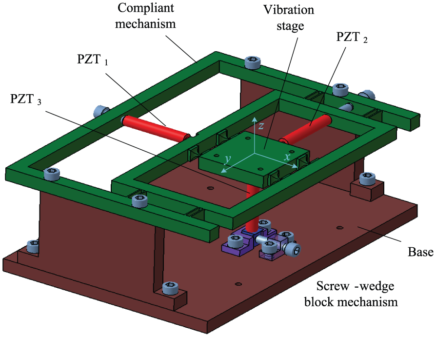
Schematic of the designed three-dimensional vibration stage.
A parallel and symmetric design is adopted to guarantee the stage do a unidirectional and stable movement. The compliant mechanism is shown in Figure 2. In order to avoid the assembly error, the compliant mechanism is manufactured as a part by wire electrical discharge machining (WEDM). The motion of y and z direction is realized by four two-axis flexure hinges with circular notches’ guidance. The motion of x direction is realized by four groups of leaf-type flexure hinges. Each group has two leaf-type flexure hinges. The four two-axis flexure hinges with circular notches have the same sizes. The eight leaf-type flexure hinges also have the same sizes. The dimensions of the two types of flexure hinges are shown in Table 1. The size of the fabricated stage is 228 mm × 158 mm × 84 mm.

Schematic of the compliant mechanism.
The dimension parameters of the two types of flexure hinges.

Working principle of the vibration stage
Without loss of generality, the driving signals of the three PEAs can be separately expressed as

where

where
The three-dimensional elliptical vibration trace of the vibration stage are acquired when the three perpendicular PEAs are given driving signals. Different positions of three-dimensional elliptical vibration traces can be obtained by adjusting the parameters like phase difference of driving signals. In addition, we also can obtain the linear vibration trace or plane (XY plane, XZ plane, or YZ plane) elliptical vibration traces by giving PEAs one or two driving signals. Different positions of vibration traces are shown in Figure 3. The vibration stage is kept horizontal during the motion.

Vibration traces simulation and its projections: (a) Ay = Az = 0, ψx = 0°; (b) Ax = Az = 0, ψy = 0°; (c) Ax = Ay = 0, ψz = 0°; (d) Az = 0, ψx = 0°, ψy = π/2; (e) Ay = 0, ψx = 0°, ψz = π/2; (f) Ax = 0, ψy = 0°, ψz = π/2; and (g) Ax = 20 μm, Ay = Az = 10 μm, ψx = 0°, ψy = π/3, ψz = π/2.
Modeling and analysis of the 3-DOF elliptical micro/nano-positioning motion stage
As shown in Figures 1 and 2, the guide mechanisms are designed to be parallel and symmetric structures in three directions. First, the stiffness in x direction of the stage was analyzed considering the characteristic of the flexure hinge type. Figure 4 is the schematic of the flexural mechanism in x direction which shows the displacement and deformations of the leaf flexure hinge structure when a force F is imposed on the midpoint. Here, it is supposed that the work of force F turn into elastic potential energy after flexure hinge deformation totally. The elastic potential energy includes rotational potential energy and tensile potential energy. They can be expressed as follows

where

Schematic of the flexural mechanism in y direction.
According to the energy conservation principle,

In general, it is assumed that flexure hinge only outputs rotational deformation. The tensile deformation is very small, and it can be ignored due to few effects compared to rotational deformation. Then, the following equation is obtained

Substituting equation (4) into equation (5), the following equation is obtained

Therefore, the stiffness of flexural mechanism in x direction can be obtained as follows

One group of leaf-type flexure hinge in x direction is studied separately. As shown in Figure 5, the left part of the one group of leaf-type flexure hinge is taken as a cantilever beam. On the basis of mechanics of materials, the following equation can be obtained


Mechanical model of one group leaf-type flexure hinge.
Based on the diagrammatic multiplication method, generalized displacement and flexible coefficient can be obtained as follows

Therefore, M can be obtained by substituting equation (9) into equation (8) as follows

The displacement of point B in x direction also can be obtained as follows

Because the leaf-type has a rectangular cross-section,

Therefore, the rotational stiffness can be obtained as follows

Substituting equation (13) into equation (7), the stiffness of flexural mechanism in x direction can be obtained
The motion of y and z direction is realized by four two-axis flexure hinges with circular notches’ guidance. And the stiffness can be derived based on Chen et al. 19
Performances testing of the 3-DOF elliptical micro/nano-positioning motion stage
Performances testing experimental setup
The developed 3-DOF elliptical micro/nano-positioning motion stage is illustrated in Figure 6 As shown in Figure 6, three PEAs (40VS12,Core Tomorrow Science Co., Ltd, Chinese), which measures φ12 mm × 51.5 mm, are embedded into the driving structures of the mechanism to achieve impact structure sizes. Capacitive displacement sensor with four measurement channels (Micro-sense DE 5300-013) is chosen for dynamic position measurements. The power amplifier (PI,E-500) which has a nominal amplification factor 1060.1 is chosen to amplify the driving signal of the PEAs. The Power PMAC controller is utilized to generate excitation signals and gather the measured displacement signals through sampled at 0.1 ms. To reduce external disturbances, all the experiments are carried out on a vibration-isolated air-floating platform (Newport RS4000). The measured noises of the three testing channels are 5.2, 4.8, and 5.5 nm root mean square (RMS), respectively.

Photograph of 3-DOF elliptical micro/nano-positioning motion stage.
Performance tests
The 3-DOF elliptical micro/nano-positioning motion stage are examined by step and sinusoidal responses to investigate the tracking performance of the motion stage system. A typical proportional–integral–derivative (PID) controller is implemented in this experiment for positioning the cutting tool. Figure 7 shows the step response of the servo system in X, Y, Z direction, CMD denotes the command displacement, and ACT denotes the actual displacement. The overshoot of the flexure hinge is very small by implementing feedback control, the steady errors are also small enough, and the rise time can reach up to 9.1 ms.

The step response of the device in the X, Y, Z direction: (a) X direction, (b) Y direction, and (c) Z direction.
Figure 8 shows the sinusoidal response of the micro/nano-positioning motion stage in X, Y, Z direction. A sine wave signal with 2 μm amplitude is employed as the command signal, and the actual displacement can well match with the command position. Meanwhile, the deviations in XYZ directions during the process are also recorded and illustrated in Figure 8(d)–(f). The maximum following error is 22 nm, it is less than 3% of the full span, and it can achieve experimental requirements.

The sinusoidal response curve and the following error of the micro/nano-positioning motion stage in X, Y, Z direction: (a, d) X direction, (b, e) Y direction, and (c, f) Z direction.
As shown in Figure 9(a)–(c), the maximum stroke of the micro/nano-positioning motion stage in X, Y, Z direction was investigative experimentally. The corresponding strokes are 10.39, 15.43, and 15.55 μm, respectively. Comparing with the stroke (36 μm) of the actuator, the decreased output motions of the PEAs may be caused by the preloading effects and the input stiffness of the mechanism.

The maximum stroke of the micro/nano-positioning motion stage in X, Y, Z direction: (a) X direction, (b) Y direction, and (c) Z direction.
To investigate the crosstalk among the XYZ direction, a harmonic voltage with 100 V amplitude and 12 Hz frequency is independently applied to the PEAs, respectively, and the obtained responses are illustrated in Figure 10(a)–(c). The stroke along the x direction and the induced deviations in y and z directions are shown in Figure 10(a). As shown in Figure 10(a), the peak-valley value of the induced coupling along the x- and y-axes are 0.031 and 0.058 μm, which are 0.77% and 1.45% of the stroke, respectively. As shown in Figure 10(b), the peak-valley value of induced coupling along the x- and y-axes are 0.035 and 0.026 μm, which are 0.86% and 0.65% of the stroke. As shown in Figure 10(c), the peak-valley value of induced coupling along the x- and y-axes are 0.014 and 0.008 mm, which are 0.35% and 0.2% of the stroke. What has been discussed above shows that the micro/nano-positioning motion stage has significant decoupling properties. The error may be caused by various factors such as inconsistent properties of the employed PEAs, inconsistent preloads of the two PEAs, structural asymmetries induced by manufacturing errors, and so on.

The sinusoidal response curve and the following error of the micro/nano-positioning motion stage in X, Y, Z direction: (a) X direction, (b) Y direction, and (c) Z direction.
Conclusion
A novel flexure-based 3-DOF elliptical micro/nano-positioning motion stage is proposed in this article, and the working principle and its stiffness analysis are detailed. Experimental tests are conducted to investigate the performances of the mechanism. The obtained strokes in x, y, and z directions are 10.39, 15.43, and 15.55 μm, respectively. The response rise time for each axis is within 10 ms, ensuring the rapid tracking can be achieved. When the axis moves, the crosstalk of the other two axes is relatively small, the maximum crosstalk in the Y direction is about 1.2% when X axis moves, and the maximum crosstalk is 0.82% and 0.11% when the axis moves in the Y direction and the Z direction, respectively. As this testing experimental is carried out on the air-bearing vibration isolation platform, the environment for complex conditions is not considered, and further study on the platform’s performance in complex conditions is needed.
Footnotes
Appendix 1
Academic Editor: Xiaotun Qiu
Declaration of conflicting interests
The author(s) declared no potential conflicts of interest with respect to the research, authorship, and/or publication of this article.
Funding
The author(s) disclosed receipt of the following financial support for the research, authorship, and/or publication of this article: This work was supported by the Department of Academy of Chinese weapon science (62201040504-A).