
Abstract
For the longitudinal–torsional composite integrated ultrasonic variable amplitude system with the longitudinal–torsional resonance produced by helical slots in the cone of the launch section, the theoretical design, finite element simulation, and experimental study are carried out. The performed analysis of the helical slot structural characteristics revealed that slot depth, helical angle, and slot width have a strong effect on the natural frequency and ratio of the torsional–longitudinal amplitude. A credible technique for adjusting the deviation of the actual system natural frequency from the theoretical design value by traditional method is proposed based on the adjustment theory of non-uniform medium adopted. The experimentally proved reduction of the above deviation strongly suggests that the approach proposed in this article provides effective theoretical guidance and experimental basis for the study of longitudinal–torsional composite integral ultrasonic variable amplitude system.
Keywords
Introduction
The ultrasonic vibration system is usually composed of an ultrasonic generator, an ultrasonic transducer, horn, and tool. In some extreme situations, the overall structure size of ultrasonic vibration system is subjected to space limitations so that it necessitates the elaboration of the integrated design of ultrasonic transducer and horn.
The longitudinal–torsional (L-T) composite ultrasonic vibration–assisted machining has more advantages than other vibration modes and can improve the cutting process and quality significantly.1–3 Tang and Zhao4–6 have designed a new type of L-T composite ultrasonic vibration system and analyzed the stability of the system. The research methods of ultrasonic vibration system include the analytical method, 7 finite element method, 8 equivalent circuit method, 9 four-terminal network method,10,11 and transmission line equation method. 12
Multiple theoretical and experimental analyses on the integrated ultrasonic vibration system have been reported.13–17 Using the wave and velocity equations, Li 13 has designed the ultrasonic transducer with a quarter wavelength composite exponential horn by theoretical calculation and ANSYS simulation. Li 14 studied the effect of the bolt length, diameter, and position on the resonant frequency of the piezoelectric transducer. Xie and He 15 investigated the impact of rear bolt on the performance parameters of transducer; Qin and Wang 16 deduced the frequency equation of the composite horn transducer via the equivalent circuit theory and adjusted the relevant parameters by accounting for the influence of electrode plate on the piezoelectric oscillator density and sound speed via a joint application of theoretical calculation, finite element analysis, and experimental data. Al-Budairi 17 proposed a novel design method of the mode converted L-T ultrasonic transducer. In the previous research, most of them are based on the single longitudinal vibration system, the integrated design of the L-T system is rare, and the calculation method is more complicated. Moreover, the correction of natural frequency errors due to non-uniform materials has never been considered.
This article deduces the frequency equation of ultrasonic transducer and horn through the analytical method and the transmission line equation method, researching on the transformation theory from the longitudinal vibration to the L-T composite vibration. Since the integrated ultrasonic variable amplitude system (hereinafter referred to as IUVAS) is composed of multiple non-uniform materials, while the resonance frequency is biased due to the influence of pre-stressed bolts, the ultrasonic variable amplitude system requires the respective modification.
Theoretical design of L-T IUVAS
The IUVAS corresponds to half-wavelength, as shown in Figure 1. The left and right parts correspond to a quarter wavelength, respectively, with the boundary position of the right end of the piezoceramic stack as the nodal surface. The sound velocity is different because of the different materials, and when the shape of the rod changes, the wavelength changes, so the length of the two sides is not equal. If necessary, the system can be designed as the integral half-wavelength component, with the left or right part of the corresponding segment adding a quarter wavelength integer multiplier. Axial-poled piezoceramic disks of the ultrasonic transducer on the left side produce the longitudinal vibration with a single excitation. Multiple helical slots have been designed on the conical part of the composite horn in the right side, and then the longitudinal vibration changes into L-T vibration, according to the modal transformation of the acoustic refraction principle.

L-T composite IUVAS.
Derivation of left-hand frequency equation
As shown in Figure 2, the left section comprises nut (I), back mass (II), and piezoceramic stack (III), which is a quarter wavelength. The displacement on the left end is the maximum and that of the right side of the piezoceramic stack is zero.

The structure of an IUVAS with the longitudinal vibration.
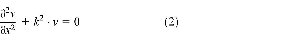
The longitudinal vibration displacement function of a uniform section bar can be expressed as

where x represents section position, A and B are undetermined coefficients, and k is circular wave number.
The longitudinal vibration velocity equation of uniform section bar is
where the vibration velocity is
Then, the general solution of the velocity equation is reduced to

The external force is derived as

where S represents the area of the cross section, E is modulus of elasticity, ρ is density, and c is acoustic velocity.
The characteristic acoustic impedance is expressed as
The boundary and continuous conditions can be expressed as follows

Suffix I represents the nut segment; suffix II the back mass segment; suffix III the piezoceramic stack segment;
Substituting equation (5) into equations (1) and (4), the frequency equation of transducer with a quarter wavelength on the left side can be deduced, which can be expressed as
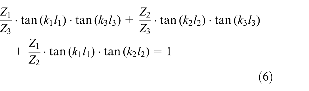
Here, Z1, Z2, and Z3 are the acoustic impedance values of sections I, II, and III, respectively, which are derived as follows:
Derivation of right-hand frequency equation
Since the calculation process of the traditional analytic method is quite complicated, the method of transmission line equation can be adopted when the composite horn with a quarter wavelength in the right end is composed of two segments.
The displacement function of longitudinal vibration and the strain function of section IV can be expressed as

As shown in Figure 2, in case of a two-section composite horn with a quarter wavelength wherein the cylinder is connected to the cone narrow edge, the longitudinal vibration transmission acoustic impedance of a cone section IV and a cylindrical section V can be obtained via the transmission line equation theory as follows

l5 is the length of cylinder.
The main section of conical section IV is the nodal plane so that the boundary condition can be expressed as

The boundary condition of equation (9) is applied to equation (7), so A is equal to zero.
On the other hand, the mechanical impedances of the left and right sides are equal at the interface between the conical section IV and cylindrical section V, while the continuous conditions can be expressed as

Applying equations (7) and (8) to equation (10), the longitudinal vibration frequency equation of the composite horn with a quarter wavelength on the right side of the joint is deduced, and its equation can be expressed as

The tapered section L-T modal transformation
The L-T composite vibration can be generated by multiple alternative techniques.18–20 For example, using two groups of piezoceramics with the axial and tangential polarizations, respectively, longitudinal and torsional vibrations can be separately produced and subsequently combined in the horn. In addition, the composite L-T vibration can be produced by two sets of ultrasonic vibration systems with a single longitudinal vibration distributed vertically. The third vibration mode transformation can be realized by reasonably designing the geometric structure of the front mass. 21 Then, the whole system is resonant in the longitudinal direction and torsional direction at same frequency. In this article, the latter method is adopted to design multiple helical slots on the composite horn, wherein the original longitudinal wave is converted into shear one according to the principle of acoustic refraction and reflection, 22 to achieve the L-T resonance. The longitudinal vibration is partly converted to the torsional vibration, and the torsional mode operates over a wide frequency range including the resonance of the longitudinal mode. So the longitudinal vibration and torsional vibration to a certain extent achieve better coupling.
As shown in Figure 3(a), there are several helical slots on the conical section, and the shape of the horn is changed. The geometric structure of the conical section consists of the external slot part and the inner solid section. The force F in the arbitrary cross section also contains two parts, which come from the external slot and inner solid, F1 represents the force distributed on the solid part of the section (Figure 3(b), blue part), and F2 indicates the force of the helical slot part of the section (Figure 3(b), yellow part). The total force F on the section can be expressed as F = F1 + F2. The proportion of F1 and F2 depends on the slot depth, whereas


The arbitrary cross-sectional torque in the conical section is
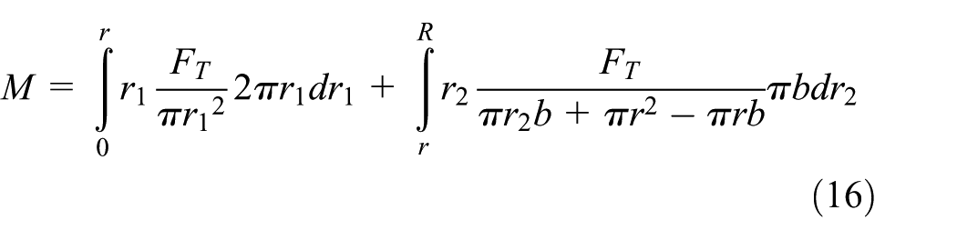
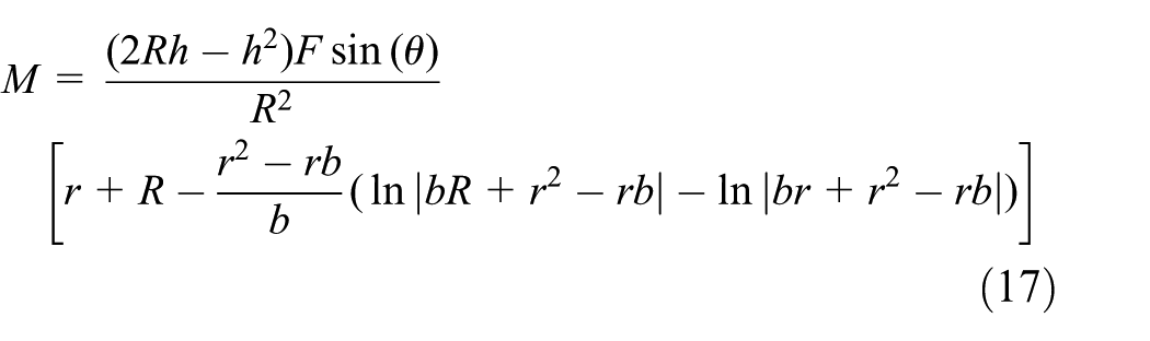
For further simplification,
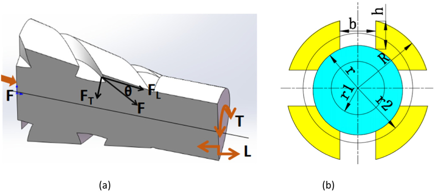
(a) The helical slot structure and (b) cross section of a cone with a helical slot.
According to equation (17), the torque in the cross section of a cone with the helical slot is related to the slot height h, width b, and helix angle
Finite element simulation
Longitudinal vibration mode simulation
To realize the energy conversion, TC4 is used in the front mass, 45# is used in the back mass, while PTZ8 piezoceramics with the axial polarization is adopted, whose specific parameters are listed in Table 1. According to equations (6) and (11), each longitudinal vibration integral horn length is calculated at 35,000 Hz, while the conical rod edges’ radii are R = 16 and r = 11, respectively.
Properties of various materials used in the IUVAS.

IUVAS: integrated ultrasonic variable amplitude system.
Insofar as the piezoceramic part size is constant, the transducer with a quarter wavelength in the left side has a fixed length. The length of the composite horn with a quarter wavelength in right side can be designed according to the specific requirements of the processing. For the convenience of the post-test data processing, we analyzed five groups of different sizes for IUVAS with a quarter wavelength horn and summarized the calculation results in Table 2. Three-dimensional simulation was carried out using the ANSYS software package. The modal simulation results show that the first set of longitudinal vibration amplitude system has a natural frequency of 34,915 Hz, the deviation from the theoretical value 35,000 Hz is 0.245%, and the average frequency deviation in the five groups is 0.8%.
The length of each segment of longitudinal vibration in IUVAS.
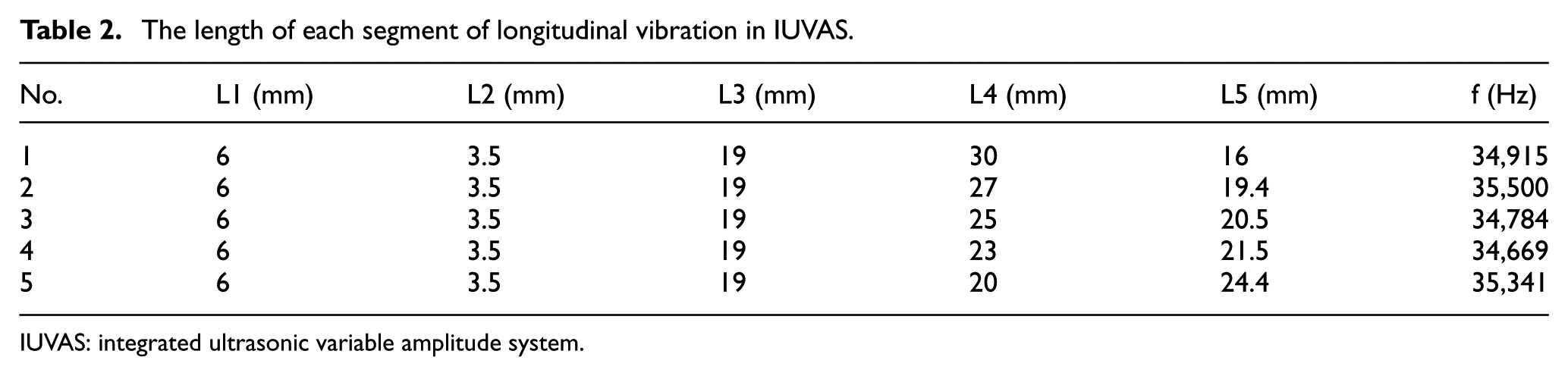
IUVAS: integrated ultrasonic variable amplitude system.
The simulation results show that the design theory of longitudinal vibration IUVAS can yield a more accurate design structure and provide a more reliable design basis. The mode simulation results in ANSYS of the first group are shown in Figure 4. The position of the nodal plane is accurate and the amplitude at the end of the cylinder is maximum.

Simulation of the longitudinal vibration in IUVAS: (a) displacement vector sum and (b) vector.
L-T mode simulation
Due to the helical slot presence in the conical section, the direction of vibration is changed by the wave refraction. The original longitudinal mode is changed into L-T resonance mode, as shown in Figure 5, where the front mass is resonant in the longitudinal and torsional directions by the force decomposition. There is the maximum longitudinal vibration amplitude at the end of the cylinder, while the torsional vibration amplitude increases gradually along the radial direction, and the amplitude of torsional vibration is most significant at the maximum radius. From the vector graph, it can be seen that the direction variation is the most pronounced in the nodal section, and its function gets saturated with the distance from the nodal section. Therefore, the shape and length of the composite horn should be rationally designed, according to the required L-T ratio. Due to the change of modes, the acoustic velocities of longitudinal waves and waves are different in the same medium, so the natural frequencies of the integrated amplitude system vary in the helical slot.

Simulation of IUVAS with L-T mode: (a) displacement vector sum, (b) vector, (c) X-component of displacement, and (d) Y-component of displacement.
As shown in Table 2, the natural frequency of the longitudinal vibration ultrasonic system is nearly identical to the theoretical value in the first group. Therefore, based on the data of this group, we suggest to realize the L-T resonance by designing the helical slot over the longitudinal IUVAS for the vibration mode. The limited simulation results for different helical slot parameters make it possible to reveal the following trends:
The slot depth h and slot width b remain unchanged, and the helical angle
The helical angle
The helical angle

The simulation results of different helical slot parameters: (a) simulation of different helical angles, (b) simulation of different slot depths, and (c) simulation of different slot widths.
System installation and experimental research
System installation
The IUVAS is formed by back mass (reflection end), PZT, copper electrode plate, front mass (transmitter), pre-stressed bolt, and other parts. To ensure the stability and reliability of the IUVAS, the respective standards should be strictly enforced in the installation. All joint surfaces need to be refined to meet the requirements of a certain degree of roughness, to ensure a close fitting of various parts for the wave transmission. The piezoceramic stack is made up of PZT-8 and the appropriate number of electrodes; the adjacent two piezoceramics have opposite directions in the longitudinal direction. The purified piezoceramics is glued using a special adhesive and then aged. When the piezoceramic is fastened, the preload is 30–35 MPa/mm2. The preload tensile force of the amplitude transformer is calculated according to the cross-sectional area of the piezoceramic and bolt. The preload force is applied via the torque wrench, to ensure the required axial force of the amplitude transformer and a close connection between the joints. 23 To avoid the vibration caused by the manufacturing and installation mismatches, the isolation slot is designed to reduce the energy loss at the flange.
Experimental study on longitudinal IUVAS
First of all, the experimental study of the longitudinal vibration of IUVAS is carried out, and five groups of vibration systems in Table 2 are installed and tested, respectively. A PV70A impedance analyzer is used in IUVAS to measure the inherent frequency (f), dynamic resistance (R1), quality factor (Qm), and other parameters. The first group of longitudinal vibration system is shown in Figure 7 and the impedance analysis result is shown in Figure 8. The electrical power is adjusted by input power and input current, P = 200 W, I = 0.2 A. The measured natural frequency value is 33,745 Hz, which is lower than the theoretical value of 35,000 Hz and the simulation value of 34,915 Hz. The error is 3.65%. While the dynamic resistance value R1 is 21.002 ohm and the quality factor Qm is 688.77, which are all within a reasonable range, the system heating is small.

The longitudinal vibration of IUVAS.
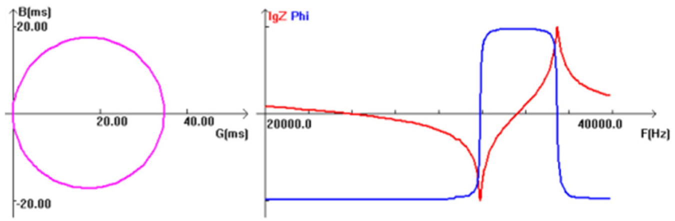
Impedance analysis results.
Figure 9 shows the measured natural frequencies and amplitudes of an integrated longitudinal vibration system under no-load conditions. Actual natural frequency values are lower than the theoretical and simulation values: the average deviation of the natural frequency is 5.4%. When the excitation is applied, the longitudinal vibration amplitude at the end of the horn is floating between 8 and 10 μm.
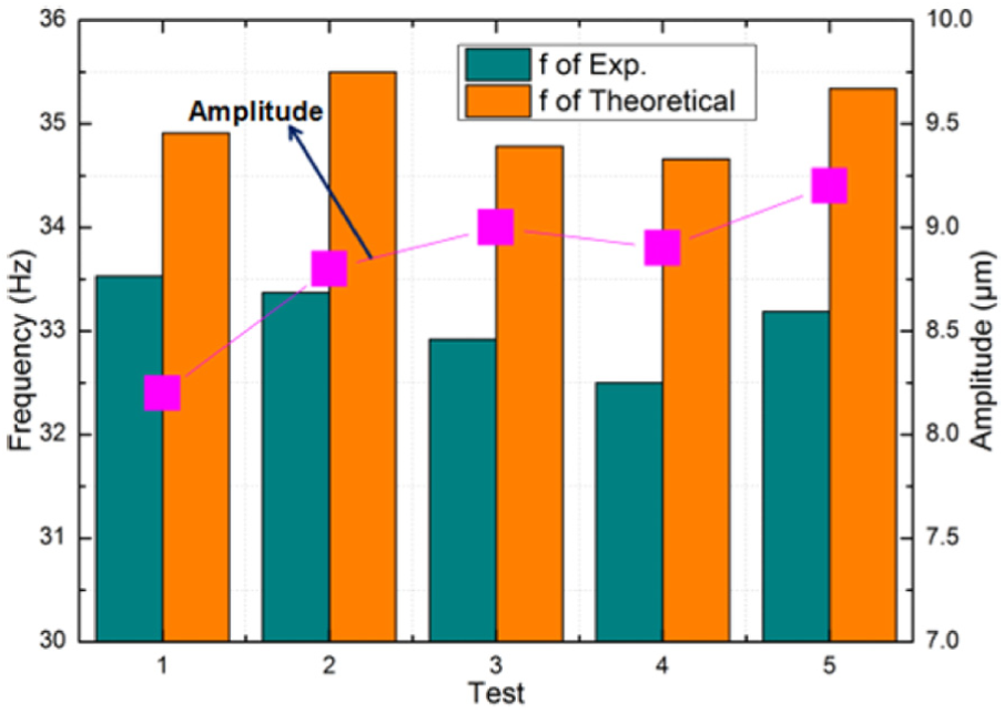
The experimental results on five groups of longitudinal vibration for IUVAS.
Experimental study on the composite L-T IUVAS
Imposing a single excitation on the composite L-T IUVAS, the end of the system will produce vibrations in the longitudinal and torsional directions, as shown in Figure 10. The system natural frequency is measured via a PV70A impedance analyzer, while a Kean LK-G10 laser displacement sensor is used to measure the longitudinal and torsional amplitudes. As shown in Figure 11, the amplitude measurement system is made up of Kean LK-G10 laser displacement sensor, computer, ultrasonic generator, transducer, and horn. The simulation results indicate that slot width b has a feeble effect on the system performance, so the experiments are subdivided into two groups. The first group of slot depth h equal to 8 mm and slot width b equal to 6 mm remain unchanged, and helix angle

Composite L-T IUVAS.
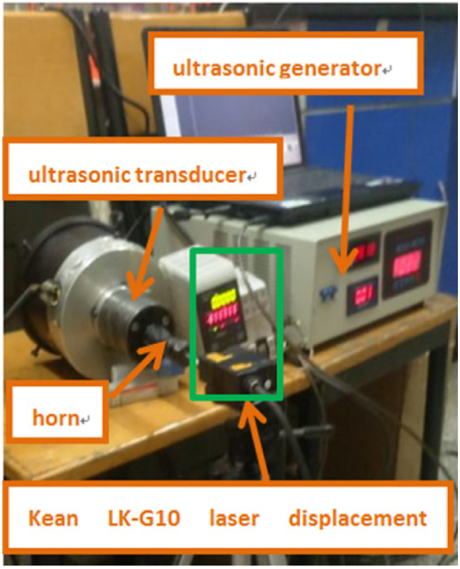
The amplitude measurement system.
As seen in Figure 12, the experimental data of L-T amplitude ratio exhibit the same trend with the simulation results, namely a variation of slot depth h can significantly increase the torsional amplitude; the helical angle is the second factor influencing the proportion of L-T amplitude, while the slot width b is the last, the least important, factor.

The measurement of the terminal amplitude of composite L-T IUVAS: (a) longitudinal and torsional amplitudes versus helix angle and (b) longitudinal and torsional amplitudes versus slot depth.
Inhomogeneous medium parameter adjustment
During the derivation of the frequency equation of integrated variable amplitude system with the longitudinal vibration, the model is simplified to facilitate calculations, that is, via the simplification of pre-stressed bolts. However, in practical applications, the structure of integrated ultrasonic vibration is complex, and such simplification will cause the system error.24,25 The main parameters of equation (11), such as density
On the left side of the nodal section, the pre-stressed bolt does not directly contact with the piezoceramic and back mass. There is no vibration propagation, so the left side can be disregarded in the frequency equation adjustment. On the right side of the section, pre-stressed bolts and the composite horn are tightly connected through the thread and exhibit a joint vibration, so any change of pre-stressed bolts’ parameters will affect the system natural frequency. In the conical section, the volume of the conical part is replaced by the bolt, so the actual equivalent density

where
The corresponding correction parameter such as equivalent sound speed is
The equivalent circular wave rate is
By introducing
Using the modified theory to redesign the longitudinal vibration composite horn with a quarter wavelength, while the other size is fixed,
Conclusion
Using a quarter wavelength theory to design the IUVAS and combining the traditional analytical method and the transmission line equation method, a simple and robust design process is proposed.
The design of helical slots in the conical section of that transmitting terminal can realize the transformation from longitudinal vibration mode to L-T composite mode. In this article, the calculation method of torque for arbitrary cross sections with the helical slot is proposed and validated by simulation and experimental results.
The finite element simulation was used to model the longitudinal vibration IUVAS. The simulation results show that the theoretical value of natural frequency is close to the simulation value, the average deviation is only 0.8%, the location of the nodal surface is accurate, and the largest amplitude of the longitudinal vibration is attained at the system edge point. The finite element method can also be used to simulate the composite L-T IUVAS, with an adequate modeling of the effect of different helix angle, slot width, and slot depth values on the natural frequency and the torsional amplitude ratio of the IUVAS. The simulation results strongly indicate that the slot depth h has a great influence on the above two factors: the natural frequency drops and the proportion of the torsional and longitudinal amplitudes increases monotonously with the slot depth h. Therefore, the slot depth h should be increased for getting larger torsional vibration amplitudes, to ensure a higher stiffness of the system. The helix angle
The experimental results show that the influence of the helical slot parameters on the proportion of the torsional and longitudinal amplitudes is consistent with the variation trend of the simulation results. In the experiment, the longitudinal amplitude ranges between 6 and 8 μm, and the torsion amplitude is between 1.4 and 5.3 μm.
The comparative analysis of experimental results revealed that the longitudinal vibration amplitude at the end of the longitudinal IUVAS varied from 8 to 10 μm. Meanwhile, the actual natural frequency of the system is lower than the theoretical value and the simulation value and ranges from 15,000 to 22,000 Hz, which corresponds to a discrepancy of 5.4%. The latter is caused by the non-uniform medium properties of IUVAS. The adjustment proposed in this article is based on the inhomogeneous medium correction theory and is shown to reduce this discrepancy to 1.43%.
Footnotes
Handling Editor: Jan Torgersen
Declaration of conflicting interests
The author(s) declared no potential conflicts of interest with respect to the research, authorship, and/or publication of this article.
Funding
The author(s) disclosed receipt of the following financial support for the research, authorship, and/or publication of this article: This research was supported by National Natural Science Foundation of China (51475148 and U1604255).