
Abstract
Planar disk springs have been widely used in recent decades due to their compact geometry, long service life, and low cost. They require no maintenance or lubrication, making them highly efficient components for a variety of applications. In this work, a device was designed and characterized to regulate the elastic constant of a disk spring by varying the effective length of its flexure arms. Its mechanical behavior was simulated using the finite element method and experimentally validated using a tensile testing machine. The ability to vary the effective length of the device’s flexure arms enables adequate performance under varying operating conditions without the need to replace the spring. The proposed device covers a broad range of elastic constants (k) and has been successfully tested as a vibration damper in an engine operating under variable loads. Real-time adjustment of this constant allows for dynamic control of the ratio between the excitation frequency and the system’s natural frequency. Since the elastic constant k is a key variable in determining the resonant frequency, modifying it makes it possible to influence the system’s vibration modes. This capability facilitates the achievement of optimal damping conditions, which are essential for ensuring system stability and preventing structural damage. In addition, two different types of disks were used in the experimental setup, depending on the weight distribution at each support point of the system.
Introduction
Planar springs have long played a very important role in industrial and technological applications, and one of their earliest uses was in cryogenic refrigerators. In the 1980s, these components were integrated into cryogenic cooling systems at the University of Oxford for space missions. 1 They can operate efficiently at extremely low temperatures and extreme conditions such as vacuum, making them ideal for applications in space that require high reliability and long service life.
In the following years, planar springs began to be increasingly used as bending bearings in linear compressors,2–7 where their main function is to restrict the radial movement of the piston, allowing axial movement, thanks to their high ratio of radial stiffness to axial stiffness. These compressors were employed in Stirling converters,2,8–14 devices that convert thermal energy into mechanical energy in a cyclic process of compression and expansion of the gas at different temperatures. Such devices have advantages such as effective sealing, high repeatability, and the elimination of lubrication, so maintenance is greatly reduced. 15 In addition, their durability contributes to the long service life of the systems in which they are used.
Today, planar springs are found in a wide range of applications, from the macroscale as earthquake dampers 16 and vehicle clutches,17–22 to micro- and nanoscale implementations in microelectromechanical systems (MEMS).23–27
One of the recurrent issues in industry is vibrations, and flat springs are widely used in numerous devices to absorb or mitigate them, which constitute one of the main focuses of this research. For instance, in the study by Dong et al., 28 a flat spring is combined with a magnetic negative-stiffness spring to isolate low-frequency vibrations. Similarly, in another investigation by Ismardi et al., 29 a flat spring is employed as the main component in an electrodynamic vibration energy harvesting device. Likewise, in the patents by Dutier et al.,30,31 a vibration damping system for an automobile transmission is described, in which a flat spring serves as the key element, effectively reducing oscillations and improving system performance.
This wide versatility of scale, plus the fact that many of these applications involve the load they carry varying and therefore affecting dynamic characteristics such as natural frequencies and vibration modes, highlights the need for a spring with adaptive behavior. To address this, we have developed a novel device: the Configurable Mechanical Energy Absorber (CMEA), designed to offer an adjustable elastic constant.
To date, variations in the behavior of springs have generally been achieved by altering the geometry, the material of the springs, or by using stacks, that is, stacking multiple elements. However, there is no solution that allows the spring behavior to be adapted in real time to changing demands. The CMEA addresses this by modifying the length of the spring arms, thus adjusting the elastic constant of a disk spring and influencing its behavior.
This article presents a detailed analysis of the behavior of the CMEA, first through tensile tests to investigate how arm length influences its performance. Next, the CMEA is incorporated in an experiment with an electric motor with eccentric masses that generate significant vibrations, which are effectively damped and absorbed by the CMEA.
The main objective of this work is to present a new configurable system that can vary the elastic constant of a planar disk spring and thus adapt to different working conditions. The elastic behavior of planar springs is characterized by using three configurations with the same geometry, based on a 100 mm diameter disk: (i) a 1 mm thick disk, (ii) a 2 mm thick disk, and (iii) a pair of 1 mm thick stacked disks. Subsequently, a practical application of the CMEA to dampen the vibrations generated by an electric motor is presented. Finally, this article presents a method to estimate the resonance frequency of the system and use this data for the configuration of the CMEA. In this way, it will operate stably within a specific regime, and better vibration absorption will be obtained. A finite element simulation of the 1 mm thick disk is also included to validate the experimental results, including its elastic constant, modal shapes, and harmonic response in different configurations.
The proposed system enables both the attenuation of vibrations generated by a system, achieving minimal amplitudes, and the attainment of larger amplitudes, which may be of interest in applications requiring controlled vibration generation. Furthermore, in future work, the system could be applied to quasi-zero-stiffness (QZS) vibration isolators, as it would allow greater control over the configuration of the system’s characteristic curve.32,33
Literature review
Disk springs: Geometries and applications
Flat (planar) disk springs are used in a wide variety of areas due to their high capacity to store and release energy in a controlled manner. In the medical sector, they are employed in orthotic devices34,35 and exoskeletons36–40 to aid the movement of limbs and joints, such as the knee and elbow joints. Their strength and durability also make them suitable for spinal implants, 41 surgical instruments, and dental devices. 42
In robotics, planar springs play an important role in mimicking natural movement, allowing smooth articulation in robotic arms, legs, and limbs.43–51 Similarly, in the medical field, they are integrated into exoskeletons and prostheses for rehabilitation35,52,53 where they assist patients with mobility problems during recovery.
Within the transport sector, particularly in automotive applications, disk springs are used in continuously variable transmissions or clutch systems,17–22 braking mechanisms, 54 and engine components. 55 They are also applied in off-road vehicles and snowmobiles18,20–22 to enhance stability and suspension performance. Specifically, planar springs have been successfully used in the suspension of a utility trailer, which has been approved by the vehicle inspection authority (ITV) and demonstrating performance equal to or even superior to that of a conventional coil suspension. 56
In the aerospace and aeronautical industries, disk springs are used in cryogenic compressors for satellites and other space systems.5,7,57–59 Their low mass, high durability, and resilience under extreme temperatures and pressures make them ideal for such demanding environments.
Additional applications include refrigeration systems4,60 and thermal machines, 61 such as Stirling engines,2,8–14 where they withstand both thermal and mechanical loads. On the micro- and nanoscale, disk springs are integral to microelectromechanical systems (MEMS),23–27 enabling precise motion control in applications like micro-positioning, micromachining, and microfabrication.
This study focuses specifically on the use of disk springs in the field of vibration. These applications include their roles as energy harvesters23,62–65 and vibration absorbers,66–69 where their dynamic response is leveraged to dampen and manage oscillatory energy.
Adjustable elastic constant device
Based on previous designs,70,71 this study features a single-stage planar-spring configuration with one key innovation: the adjustable arm length, inspired by the patent. 72 Previous research 73 has already shown that the length of the spring arms is a critical parameter that influences elastic behavior and therefore must be considered. Instead of using multiple springs with different geometries and behaviors, our design allows real-time adjustment of the effective arm length, allowing the spring to exhibit different mechanical behavior by adapting it to the required conditions.
The prototype disk spring features an outer diameter of 100 mm and consists of three flexible arms arranged tangentially to the disk curvature. Each arm spans ∼100° and has a radial reach of 30 mm. Three configurations are evaluated: a 1 mm thick disk, a 2 mm thick disk, and a stack of two 1 mm thick disks. The design is illustrated in Figure 1(a)).

(a) Disk spring, with three arms, (b) CMEA device and (c) CMEA exploded model.
The spring is integrated into a manually adjustable device, shown in Figure 1(b) and (c), which enables real-time control of the arm length. The mechanism includes a red ring with three limiters that define the usable length of each arm—thereby controlling the spring’s stiffness. The device components were fabricated via 3D printing using selective laser sintering of polyamide. These include: the base that secures the spring (gray), the adjustable upper and lower rings (red), and gray handles that enable manual tuning. A graduated scale from 0° to 100° is included to provide precise control over the arm’s length setting.
The complete assembly is called a configurable mechanical energy absorber (CMEA). This name reflects its main function: to configure the elastic constant in real time to adapt to the required operating conditions.
Methodology
The steps that have been followed in the research are included in Figure 2 and are explained in this section.
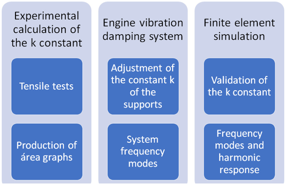
Research methodology.
For the tensile tests, clamping components were manufactured to adapt the CMEA to the traction machine (Figure 3(b)). A Formiga P100 EOS laser sintering printer (see Figure 4(a)) was used; it is very useful for prototyping and manufacturing small components. It has the advantages of high dimensional accuracy, efficient powder reuse, and cost-effectiveness. 74 The tensile tests were carried out with the Tinius Olsen H25KS universal testing machine, which supports loads of up to 25 kN and allows precise tensile, compressive and flexural tests, where the mechanical behavior of the CMEA is evaluated. 75

(a) 3D EOS Formiga P100 printer, (b) Tinius Olsen H25KS tensile tester, (c) PCE VM 5000 4-channel accelerometer and (d) PCE-VT 3900 vibrometer.

(a) CMEA and adapter manufactured by 3D printer for the tensile test and (b) CMEA tensile test.
In the experiment on absorbing vibrations from an engine, two instruments were used for data acquisition. The PCE VM 5000, a 4-channel accelerometer, to measure vibration amplitudes 76 and the PCE-VT 3900 vibrometer to determine the rotation frequency of the motor.
Calculation of the elastic constant k
The elastic constant k was determined by a series of tensile tests, in which an axial tensile force was progressively applied to the CMEA. Data were recorded from each test on both the applied force (in Newtons) and the resulting axial displacement of the inner disk relative to the outer ring (in millimeters)
The main objective of these tests is to represent the force-displacement curves that characterize the elastic behavior of the system. The Tinius Olsen H25KS universal testing machine was used for tensile tests, equipped with accessories made with the EOS Formiga P100 SLS 3D printer. These fittings were specifically designed to adjust the unique geometry of the CMEA (Figure 4).
During each test, an increasing axial force was applied, always considering predefined limits of maximum force and displacement to prevent plastic deformation or even breakage of the springs. The data obtained were used to draw elasticity curves, in this way the behavior of the springs for each configuration can be characterized.
Three spring configurations were tested:
A single disk with a thickness of 1 mm.
A single disk with a thickness of 2 mm.
A stacked configuration consisting of two 1 mm thick disks (referred to as the “double spring”).
Stacked planar springs, referenced in previous studies,16,77–80 offer greater adaptability since they allow rigidity adjustments through simple changes in the number of spring elements, adding or removing according to the requirements of each case.
All tests were carried out in an angular adjustment range of 0°–100°, to evaluate the spring response at different arm lengths.
The data from each test were classified according to the spring configuration and the angle of attachment of the arms. Next, a linear regression analysis was applied to each force-displacement curve to obtain the slope, which corresponds to the elastic constant k for each of the configurations we have determined at each angle.
Experimental setup
To evaluate the dynamic characteristics of the CMEA, a vibration-damping experiment was designed. This setup consists of a motor with eccentric masses coupled to adjustable springs (CMEAs), forming a system that simulates real-world vibration conditions. The experiment includes five essential components, as illustrated in Figure 5.
Motor (1): The motor serves as the excitation source for the system. It generates vibrations by rotating two eccentric masses mounted at either end of its axes. The motor itself has a mass of 11 kg.
Top plate (2): This aluminum plate connects the motor to the CMEAs. It can accommodate either three or four support points, depending on the test configuration. The plate measures 290 × 290 mm and weighs 7.2 kg. In the experiment, three supports will be used.
CMEA and support assembly (3): Each CMEA is mounted on a custom support that elevates it, allowing for free axial deformation. These supports also enable secure attachment to the top and bottom plates. The CMEA units are the core damping elements of the system.
Lower plate (4): The lower plate anchors the CMEA supports and transmits loads to the base. It acts as an intermediary structure between the damping elements and the experimental foundation.
Heavy element (5): A heavy base weighing 257 kg, serves as the foundation of the entire system. Its primary function is to isolate the experiment from external sources of vibration, such as floor oscillations or adjacent equipment.
Frequency controller (6): It transforms the frequency of the electrical network and regulates the power supplied to the motor, thus allowing its rotation speed in hertz to be adjusted according to the system requirements.

Components of the experiment setup.
Once the experimental setup is fully assembled, a systematic procedure is followed to collect accurate data. This includes the determination of three key parameters: total load, support placement and load distribution, and natural frequency. These variables are calculated according to the methodology outlined in Hua and Thomas. 81
To determine the total load, the combined mass of the motor and top plate was measured at 18.2 kg. For the support configuration, the system was mounted on three CMEA units. A central upper support carries 9.1 kg, while each of the two lower lateral supports bears 4.55 kg. This distribution ensures structural balance and symmetrical loading. These masses were calculated by using a precision scale on each support (Figure 6).
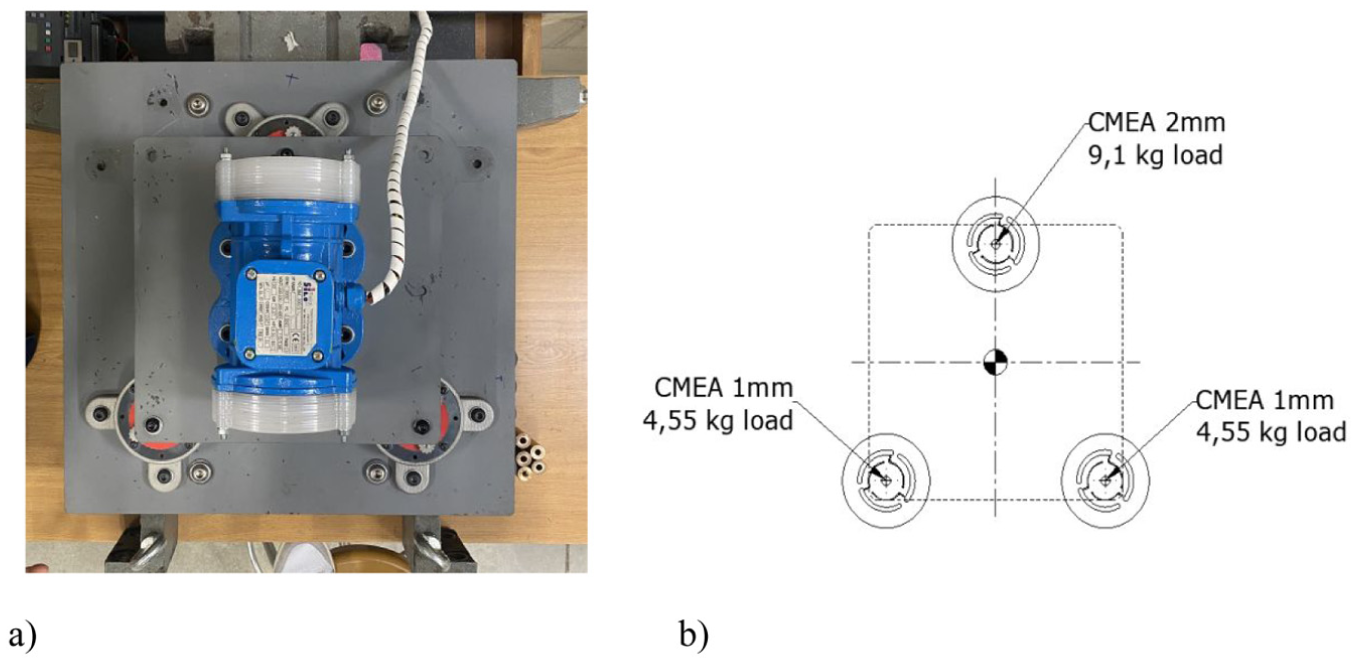
(a) Top view of the assembly and (b) schematic showing load distribution across three supports.
The system’s behavior is governed by the fundamental relationship for harmonic oscillators, shown in equation (1):

Where:
f is the natural frequency (Hz),
k is the elastic constant of the spring (N/m),
m is the mass supported by the spring (kg).
This equation highlights the direct dependence of system frequency on both the spring stiffness and supported mass. By varying these parameters, the experiment aims to validate the theoretical relationship and evaluate the CMEA’s ability to adapt to different dynamic conditions.
Finite element simulation of the behavior of a planar spring with adjustable k constant
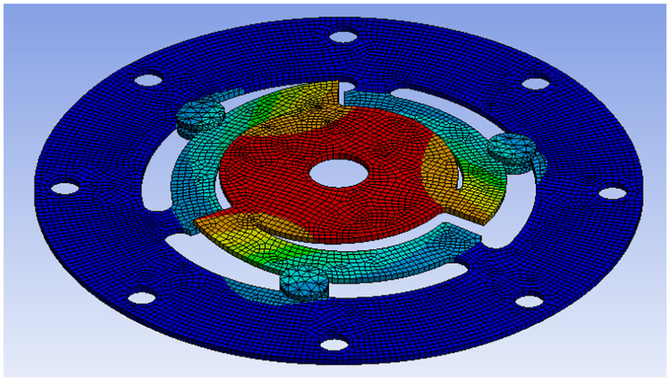
The geometry used for the finite element analysis can be seen in Figure 7. It is the planar disk of 1 mm thickness, to which some fasteners have been added, so that according to their position the effective length of the arms varies between 0° (left) and 100° (right). Five positions of the fasteners have been represented, although in the simulations 10 positions were considered (every 10° of arm length).

Geometry used for finite element modeling for different positions of the fasteners: (a) 0°, (b) 25°, (c) 50°, (d) 75° and (e) 100°.
Three-dimensional models were developed using SolidWorks® and subsequently exported to finite element analysis (FEA) software, namely ANSYS Workbench. The numerical simulations were designed to reproduce, as accurately as possible, the tensile tests performed on the physical dis specimens. The final model assumes the bolt holes of the disk to be fully constrained, while an axial load is applied to the inner surface of the disk. The contacts between the disk and the fasteners, as well as between the disks and the spacer rings, were modeled using bonded contact conditions. A mesh convergence study was conducted considering maximum element sizes of 2.0, 1.5, 1.0, and 0.5 mm. Based on this analysis, linear mechanical elements with a maximum size of 0.5 mm were selected. For the disk with a thickness of 1 mm, the final mesh consisted of 86,791 elements. The material was modeled as linear elastic 51CrV4 steel. The spring stiffness k was computed as the ratio between the applied axial force and the resulting axial displacement.
In addition to the static analysis, a modal analysis was performed to identify the natural frequencies of the system, followed by a harmonic response analysis.
Results
Spring behavior in experimental tests on tensile machine
As detailed in Section 3.1, force versus displacement data were recorded for various angular positions of the arms anchoring points (from 0° to 100°). This procedure was repeated five times for each type of disk tested: 1 mm thick disks, 2 mm thick disks, and the “double 1 mm” disk. Repeating the experiment is essential to obtain reliable and robust results because it minimizes the impact of random errors, identifies outliers, evaluates the variability of the system, validates the experimental methodology and strengthens the conclusions from a larger and more reliable data set.
Through a linear regression analysis, the lines that best fit the data corresponding to each position or angle are determined (Figure 8). Subsequently, the slope of these lines is extracted, which represents the elasticity constant of the system.

Displacement versus force chart for each angle of the 1 mm thick CMEA.
Table 1 presents the mean value and standard deviation of the elastic stiffness constant for each angle, calculated from the five tensile tests performed for each thickness configuration (1 mm, 2 mm, and double 1 mm). Figure 9 illustrates the variation of the elastic stiffness constant as a function of the angle for the three spring configurations, including error bars representing the standard deviation of the measured values.
Values of elastic constant (k) as a function of angle, for CMEAs of 1 mm, 1 mm double, and 2 mm.


Table and graph showing the values of elastic constant (k) as a function of angle, for CMEAs of 1 mm, 1 mm double, and 2 mm.
From the equations of the obtained straight lines, lower and upper limits have been established to define the range of the elasticity constant k corresponding to each type of spring, as a function of the applied load and the desired displacement. Finally, a global graph including the three spring types (represented in yellow) has been elaborated. This representation makes it possible to observe the variation of the elasticity constant k in relation to load and displacement for the three types of spring evaluated, which is a key aspect in the analysis of the CMEA performance (Figure 10).
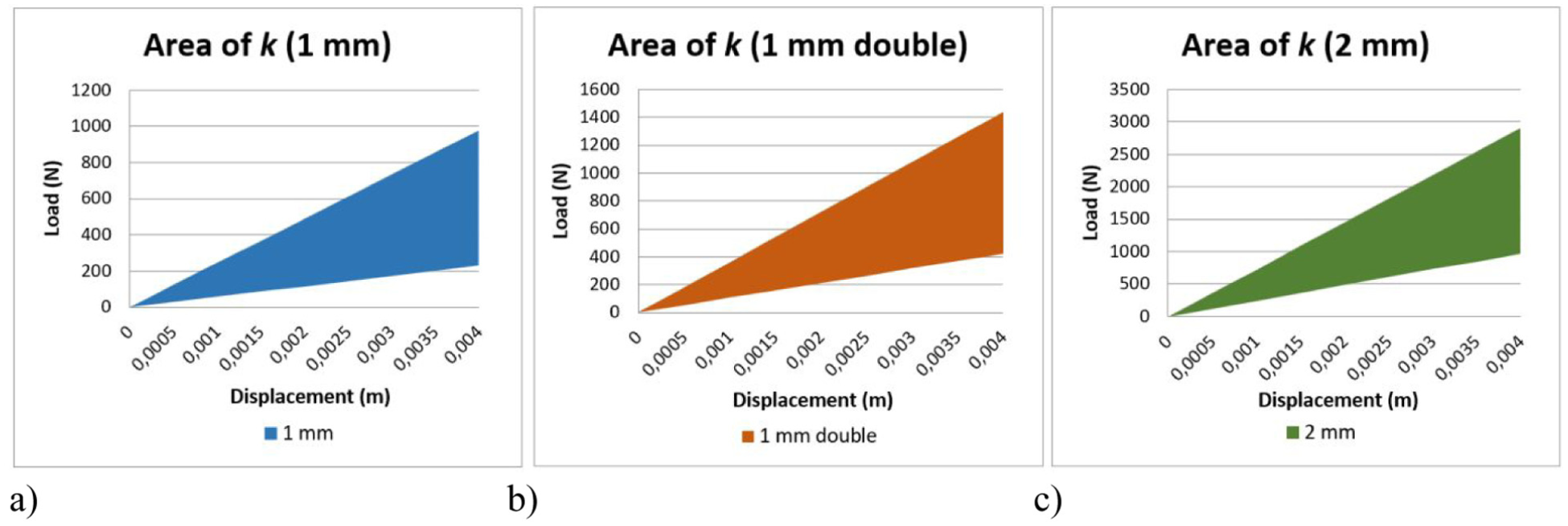
Load-displacement plots showing the area covered by the: (a) 1 mm, (b) 1 mm double and (c) 2 mm CMEAs.
In summary, a test was carried out to determine the elasticity constant k of three springs, with the adjuster in various positions to evaluate their behavior. The data obtained have been plotted in graphs, and by means of a linear regression the elasticity constant k has been calculated. Considering the three springs and all the possible positions of the regulating device, the graph shown in the figure below has been drawn up (Figure 11).

Load-displacement plot showing the combined area covered by the 1 mm, 1 mm double, and 2 mm CMEAs.
Electric motor test bench
The objective of the experiment with the motor is to validate the theoretical calculations related to the natural frequency of the system, to achieve adequate damping. For this purpose, the three supports of the motor have been prepared, the details of which are illustrated in the sketch in Ssection 3.2. The upper support, which supports a load of 9.1 kg, is composed of a CMEA incorporating a 1- or 2-mm thick disk, while the lower supports support 4.55 kg each.
Knowing the maximum load tolerated by each support and the objective of reaching a given natural frequency for the CMEA, the elastic constant of each support can be calculated using equation (1). Table 2 shows the four checks of the natural frequency, in which we wanted all the support to have the same resonance frequency by adjusting the constant of elasticity, by means of the regulation system.
Values of the angle and its elastic constant to obtain a natural frequency of 25.25 Hz for 1 and 2 mm thick CMEAs.

The motor experiment was carried out, in which the deformation amplitude of both the motor and the base was recorded at different frequencies in the 1 Hz ranges which was achieved with the frequency controller by adjusting the rotation speed of the motor. In the resonant frequency range, amplitude values were recorded every 0.5 Hz. The results showed that, as the frequency increased and approached the natural frequency of the system, the oscillation amplitudes increased markedly. A similar behavior was observed when starting the experiment with a higher frequency and decreasing it to approach the natural frequency.
In addition, a significant damping of the vibrations transmitted from the motor plate to the base was observed, with a reduction of the deformation amplitude (Figure 12).
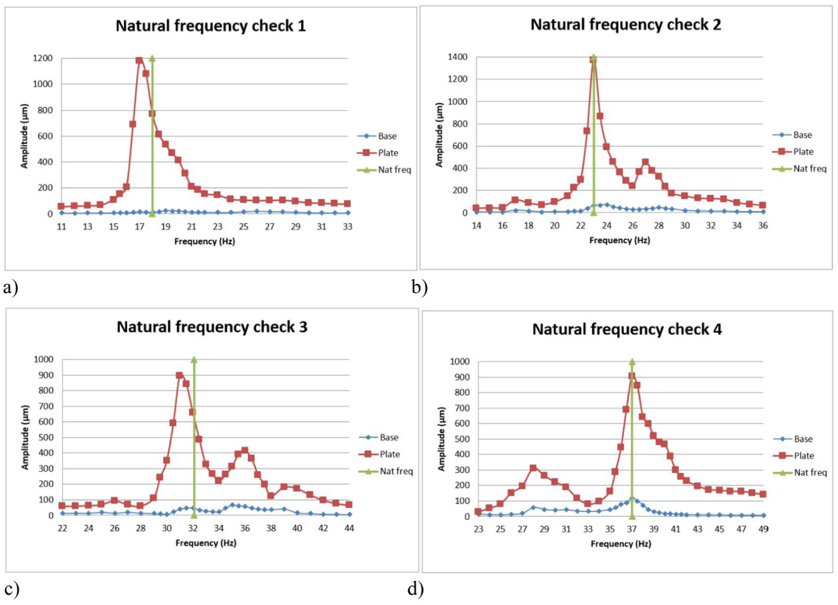
Amplitude versus frequency plots for the base and top plate: (a) check 1, (b) check 2, (c) check 3 and (d) check 4. Natural frequency check.
This validates that it is possible to theoretically calculate the natural frequency of the system, in addition to achieving significant vibration damping.
Case study
The main objective is to achieve effective damping in the system and for this a certain relationship between the natural frequency and the excitation frequency is required. For this study, a case is proposed in which the excitation frequency is 40 Hz, this implies that this excitation frequency must be at least 1.41 times higher than the natural frequency, making the calculations (40/1.41), the resonance frequency must be 28.29 Hz or lower. However, to achieve more effective damping, it is necessary to move the natural frequency further away from the excitation frequency. To do this, the process used above is repeated.
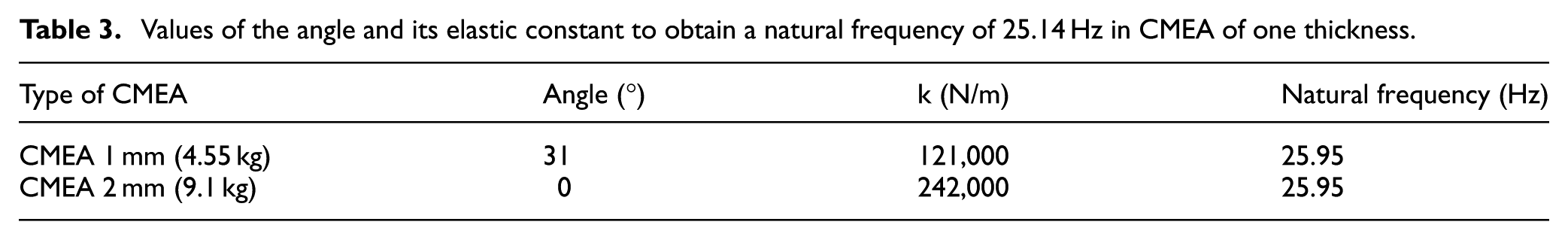
We try to achieve a natural frequency of ∼25.95 Hz, well below the 28.29 Hz that would be the maximum, to have better damping. For this case we are going to use the CMEA 1 and 2 mm springs (Table 3).
Values of the angle and its elastic constant to obtain a natural frequency of 25.14 Hz in CMEA of one thickness.
In the analysis of the motor experiment, it was observed that, as the natural frequency of 25.14 Hz was approached, both below and above, increasingly pronounced oscillations were generated. The objective of this experiment was to confirm the effectiveness of vibration damping for a system excitation frequency set at 40 Hz. The results indicate that the oscillations at the motor plate reached an amplitude of 0.075 mm, while the oscillation amplitude transmitted to the base was only 0.006 mm (for 40 Hz), representing a 92% reduction (Figure 13).

Plot of amplitude versus frequency for the base and top plate. Damping for an excitation frequency of 40 Hz.
Spring behavior in finite element simulations
Figure 14 shows the deformation of the spring once the force is applied. Table 4 and Figure 15 show the k of the device for each arm opening (measured in angle), superimposed with the k obtained experimentally on the tensile machine. Almost identical behavior is observed, except for the higher angles,50–80 which is considered acceptable. It is important to note that the experimental data presented represent the average of all measurements taken.
Finite element simulation of the spring, deformation for 50°.
Comparison of the elastic constant obtained experimentally and by simulation.

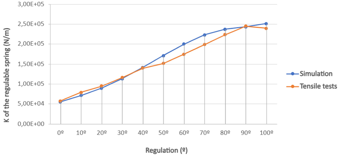
Comparison of the elastic constant obtained experimentally and by simulation.
On the other hand, once the modal analysis was performed, and as an example, the natural frequencies obtained for an angle of 50° were 713.86, 1132, 1158.1, 2306.2, 2337.1, and 2409.2 Hz. The following figure shows the deformations for these frequencies (Figure 16). These values are far from the resonance frequencies of the motor-spring assembly seen previously.
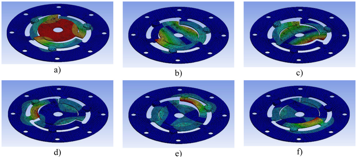
Deformations for the six obtained frequency modes: (a) first mode, (b) second mode, (c) third mode, (d) fourth mode, (e) fifth mode and (f) sixth mode.
Figure 17 shows the modal frequencies as a function of arm length. The greater the angle, the higher the frequency. It should be noted that the curve for mode 2 and that for mode 5 are not clearly distinguishable in the figure. This is because the frequencies for modes 2 and 3 are so close that the curves overlap. The same is true for modes 5 and 6.

Frequency modes according to arm length.
Finally, Figure 18 shows the harmonic response of the system for a weight of 91 N, which is the weight supported by one of the motor supports on which the adjustable disk has been tested. The behavior is more stable in the middle area, with more pronounced peaks at the end.

Adjustable spring harmonic response.
Conclusions
In this research study, a comprehensive analysis of the operation and properties of an adjustable elastic constant disk spring is presented. This component, characterized by its cost-effectiveness and straightforward manufacturing process, can be integrated into variable-rate systems, as it permits precise real-time adjustments aligned with the operational conditions of the system. To date, in the existing scientific literature, no device has been found that it has characteristics like those described in this work.
The planar spring with an adjustable elastic constant in a damping system has been successfully used. To obtain adequate damping, you need to know the value of the excitation frequency and the resonance frequency of the system.
The ratio of excitation frequency to natural frequency (fexc/fnat) should be >1.41 (the square root of 2). If this requirement is met, better damping is guaranteed. If you get a ratio below 1.41, the damping is less and therefore there will be more vibrations. Therefore, the natural frequency of the system must be reduced since the excitation frequency is considered fixed, thinking of industrial machine applications that have a working frequency, and it is not possible to modify it.
To decrease the frequency of resonance, there are two options, either increasing the mass of the system or decreasing its elastic constant. Our device is suitable for the latter alternative, as it allows the variation of the spring constant (k), dynamically adjusting the ratio (fexc/fnat). With this device, the system can be controlled to obtain better cushioning, guaranteeing the stability of the system, and avoiding possible damage.
In addition, the behavior of the adjustable device has been validated by finite element simulation with promising results. These simulations allow the characterization and optimization of the various design configurations and adapt them to specific applications, before the device is manufactured.
Footnotes
Handling Editor: Stefano Manzoni
ORCID iDs
Ethical considerations
There are no ethical concerns in this research work.
Funding
The authors disclosed receipt of the following financial support for the research, authorship, and/or publication of this article: This work was supported by the Public University of Navarre under the Promotion Plant of Research Groups 2025 and by the Government of Navarre (Department of University, Innovation, and Digital Transformation) under predoctoral grant 0011-0537-2024-000062.
Declaration of conflicting interests
The authors declared no potential conflicts of interest with respect to the research, authorship, and/or publication of this article.
Data availability statement
All material and data are available in the manuscript.