
Abstract
The operation disturbance induced by the solar array drive system (SADS) and the residual vibration of solar array following the attitude adjustment of the spacecraft obviously affect the dynamics environment, quick stabilization, and attitude stability of the high-precision spacecraft. However, these two kinds of vibration disturbance are characterized by distinct vibration categories, direction of vibration, and modal shapes. A multi-degree-of-freedom vibration reduction strategy (VRS) was presented to improve the dynamic characteristics of SADS and then to weaken these disturbances synthetically in this paper. SADS applying this VRS was modeled based on the virtual work principle, and the influence of the stiffness and damping parameters of this VRS on the SADS dynamic characteristics was analyzed. Then a prototype of vibration reduction device (VRD) was designed and verified by disturbance characteristic and modal experiments. The results indicate that the equivalent stiffness of VRD is critical to the natural frequency of SADS and thus should be carefully deliberated to avoid resonance. The equivalent damping of VRD always has positive correlation with modal damping. A good performance up to 40% in terms of operation disturbance suppression and a greater than 56% decrease of the damping time for 99% residual vibration have been obtained.
Introduction
The different-configurations overhang solar arrays on the modern spacecraft may cause two kinds of vibration disturbance. The first, the residual vibration of solar arrays cannot be attenuated for a long time due to the characteristics of low frequency and low damping after the attitude adjustment of the spacecraft and instantaneous thermal load, which greatly affects the attitude stability time and quick response ability of the spacecraft. The second, these solar arrays rotate continuously to orientate the sun for collecting solar energy as much as possible. However, the motion of solar array induces unremitting disturbance to the body of the spacecraft, affecting the pointing accuracy of the high-precision spacecraft and the dynamic environment of the sensitive equipment.1–4
On the one hand, the residual vibration belongs to free-vibration problem, occurring in the out-of-plane direction, and is mainly related to the bending modes. The purpose of residual-vibration suppression is to accelerate the vibration reduction and shorten the time required for vibration stability. Researchers have studied the mechanical vibration reduction methods for the residual vibration of solar array from passive and active aspects. The damping technology is primary used in the passive vibration reduction of solar array. The solar array damper on the Hubble Space Telescope is a typical application of passive vibration reduction method. As shown in Figure 1(a), this damper consists of upper and lower shear plates, and the damping layer fixes on the yoke of solar array.5–8 The damping layer goes through shear deformation and dissipates the vibration energy due to the relative displacement between the upper and lower shear plates in the vibration process. Brugarolas et al. 9 reported the structural redesign plans on this damper, as shown in Figure 1(b). Liu 10 replaced the viscoelastic damping material in the damping layer with the polymer damping material, and studied the effect of temperature on the properties of the damper via simulation and experiment. The results showed that the modal damping ratio increases gradually with the environmental temperature. Wang 11 studied the function of this damper on the attitude stability of the spacecraft. Bose and Gorain 12 studied the vibration control of solar array with an ideal damper at the hub end, and he found out that the control force is proportional to a general nonlinear function of the vibration velocity, in which both torsional and bending modes are considered. Kong and Huang 13 designed a passive vibration damping device for solar arrays with a viscous damper to provide tilted support near the root hinge. Jia et al. 14 reported a novel damping platform for large flexible overhanging structure, which is composed of spherical hinge, multi-damping rod and rigid support. Simulation results show that this damping platform has damping effect on the motion of spacecraft and the vibration of flexible structure. Kong and Huang 13 reported a novel configuration of solar array damper for bending vibration, in which the upper strut contains a viscous damper and the lower strut is rigid. This damper is lockable and located near the solar array root hinge, increasing structural damping without reducing the base frequency.

Typical passive dampers of solar array: (a) damper on Hubble Space Telescope and (b) improved dampers under investigation.
In the aspect of the active vibration reduction for the residual vibration of solar arrays, Baier et al. 15 and Baier and Reindl 16 analyzed the application prospect of intelligent materials in the vibration control of a variety of flexible structures on the high-precision spacecraft, and firstly studied an active damper using piezoelectric material fixed between solar array and the spacecraft body for weakening the influence between the vibration of solar array and the attitude motion of the spacecraft. Weck and Hollister 17 implemented the vibration control of solar array based on the decentralized control method with a low area density by embedding shape memory alloy wires. Nye et al. 18 developed an intelligent support embedding piezoelectric material into the connection of solar array and the spacecraft, which provided a 12% raise in modal damping ratio and up to 40% dissipation of the vibration energy actively. The active control strategy based on piezoelectric sensor and actuator has been verified in the ground experiment of the ACTEX-II plan to attenuate both the torsional and bending vibration of solar array during its attitude adjustment processing. 19 Chen 20 utilized shape memory alloy wires as actuator and investigated vibration control of solar array by introducing classic linear optimal control theory. Abdeljaber et al. 21 and Qiu et al.22–25 presented an active vibration control method subjected to plate-type flexible structure on the spacecraft by piezoelectric actuator and sensor as well as nonlinear adaptive golden section controller or intelligent neural network controller. Hu 26 simplified solar array as a cantilever beam, and discussed the coupling control problem of the attitude motion of spacecraft and the vibration of solar array by pasting piezoelectric actuators and sensors. Jiang and Li27,28 studied smart-structure mixed-sensitivity H∞ robust decentralized controller of solar array, and efficiently suppressed vibration induced by external disturbance in absent of control overflow, presented a new intelligent methodology.
On the other hand, the operation disturbance is part of forced-vibration problem, occurring around the driving shaft, and mainly related to torsional modes of SADS. The purpose of operation-disturbance suppression is to reduce the disturbance amplitude, avoid structural resonance by staggering the sensitive frequencies. Many literatures have reported investigations on the operation-disturbance suppression of SADS. Doherty and Tolson, 29 Freitas, 30 Zhu et al., 31 and Na et al. 32 are interested in operation-disturbance suppression problems related to the intermittent drive strategy, in which the solar array completes a short-time operation and vulnerable payloads works in the interval between successive two operations of solar array. Atlas and Thomin 33 studied the driving compensation method of solar array drive assembly (SADA) without intermission, in which the reluctance stepper motor was responsible for providing the driving torque. They reported an improved “sinusoidal” drive profile to achieve motion stability requirements and reduce system errors caused by various defects in the control loop and stepper motor. Iwata et al. 34 did not adopt a fixed driving pulse mode, but a slightly randomized driving pattern, which has a strong irregularity and can avoid excitation resonance of solar array. Zhang et al. 35 added an additional term into the reference winding current to compensate the driving torque harmonic component, which improved the angular velocity stability of SADS. Si et al. 36 designed a feasible current compensation method for closed-loop winding, and improved the robustness of the system by using adaptive control. Zhou et al. 37 considered the uncertainty in SADS and introduced the input shaping method based on the reference model and adaptive robust control into the operation disturbance suppression problem.
Since the residual vibration and operation disturbance belong to different vibration categories, occur in different degrees of freedom, and involve divergent vibration modes, the vast majority of the above study concerned on one of the two vibration reduction problem, without systematically improvement on the overall dynamic characteristics. The research on residual vibration suppression mainly focuses on improving the equivalent damping by mechanical measures and active control, while the investigation on operational disturbance mainly focuses on using different driving control strategies and frequency-adjustment measures to avoid the coupling between the characteristic frequency of disturbance and the natural frequency of the structure. It is undoubted that the vibration reduction problem of SADS is simplified by considering the operation disturbance and residual vibration problems respectively. However, two sets of vibration control measures undoubtedly increase the amount of system design, overall weight, and capital cost.
To this effort, a multi-degree-of-freedom VRS with an adjustable stiffness mechanical VRD arranged between the solar array and the drive assembly (as shown in Figure 2), was presented to improve the dynamic characteristics of structural systems and then to weaken these two kinds of vibration disturbances synthetically in this paper. It begins with the dynamic modeling of SADS with VRD based on the virtual work principle and the hybrid coordinate description. The influence of the equivalent parameters of the VRD on the modal dynamic characteristics of the torsion and bending modes was then analyzed theoretically. Moreover, an elementary prototype of VRD was designed based on above analysis results. The drive disturbance experiment system and modal parameter measurement system were implemented to verify the effectiveness of VRD on solving the above vibration-reduction problems, respectively. This paper is closed by conclusions, which highlight the innovation points and recommendations for future research directions.

Layout view of VRD and coordinate system: (a) definition of the space-fixed coordinate frame and (b) definition of the body-fixed coordinates frame of solar array and VRD.
Dynamic modeling of the solar array drive system with the vibration reduction device
Assumption and coordinate system
In order to investigate the effect of VRD on the dynamic characteristics and responses of SADS, the following assumptions are introduced:
The spacecraft body is rigid body and its translation and rotation displacement are constrained;
The angular displacement of the SADA is small quantity within a short time;
The VRD has stiffness and damping features, and its structure size and mass feature are relatively small compared to the developed solar array;
Nonlinear stiffness of the development and locking mechanism on solar arrays is ignored in the case of small deformation;
The spacecraft body, SADA, VRD, and solar arrays are connected rigidly.
In view of above assumptions, the spacecraft body can be considered as a fixed boundary, and VRD is simplified as an elastic-damping connection with six degrees of freedom, as shown in Figure 3. The coordinate systems are defined (see Figure 2) as follows:
The space-fixed coordinate frame. The origin, O, locates at the center of the separation surface between the spacecraft and its launcher; the OZ axis points to the flight direction; the OY axis points to the development direction of solar array; the OX axis is determined by the right-hand rule.
The body-fixed coordinate frame of solar array. The origin, o, is assigned at the center of the installation interface of VRD, the oy axis orientates to the developing direction; the ox axis is perpendicular to the plane of solar array; the oz axis is determined by the right-hand rule.
The body-fixed coordinate frame of the VRD. The origin, od, locates in the center of the installation surface of the spacecraft and VRD, and the coordinate axis orientates to the same direction as oxyz before deformation.
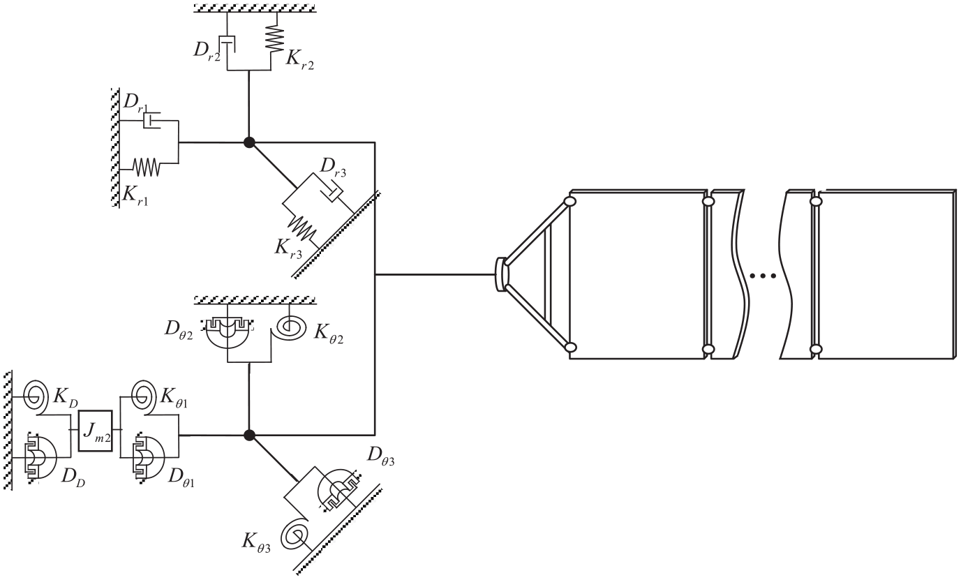
Equivalent analysis model for dynamic characteristics of the drive system with VRD.
Kinematics representation of the solar array drive system
The hybrid coordinate system is employed to describe the kinematics relations of SADS with VRD, in which the geometry and modal coordinates, respectively, declare the rigid motion of VRD and solar array and the deformation of solar array in its following coordinate. The translation and rotation displacements of VRD respect to the space-fixed coordinate are

where
The angular displacement, velocity, and acceleration of solar array respect to the space-fixed coordinate are

where
The position vector of the kth node on solar array (as shown in Figure 2) is

where

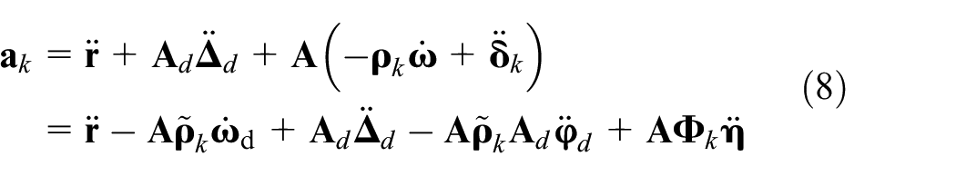
The velocity and acceleration of the kth node are

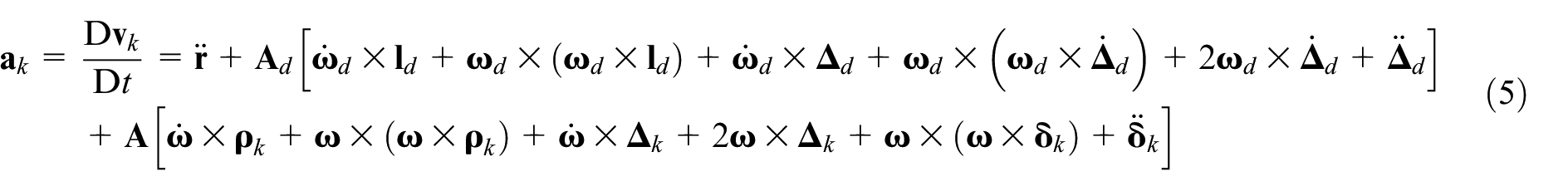
where

On the other hand, the virtual displacement of the kth node is

Because

where the vibration displacement
Dynamics representation of the solar array drive system
The virtual work of inertial force introduced by SADA and solar array is
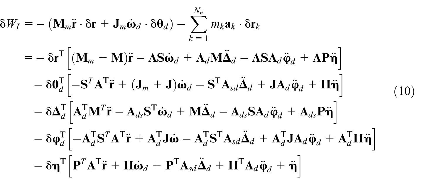
where
The elastic potential energy contains the mode deformation energy of solar array and the translation and rotation deformation energies of VRD, thus the virtual work of internal force is
where

where
In absence of disturbance of space environment and excitation of the spacecraft bode, the drive torque is the only external force of solar array, and the virtual angular displacement related to the drive torque only occurs in the driving direction. Thus, the virtual work of external force can be written as

where
Generalized coordinate vector,

where

where
in which s modal truncation order. Utilizing Lagrange multiplier,
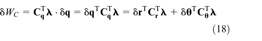
where
Dynamic model of the solar array drive system
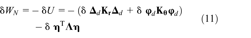
The virtual work of solar array is induced by inertial force, external force, internal force, damping force and constrain force, so the virtual work principle of solar array is expressed as

Substituting equations (10) to (13) and (18) into equation (19) and arranging

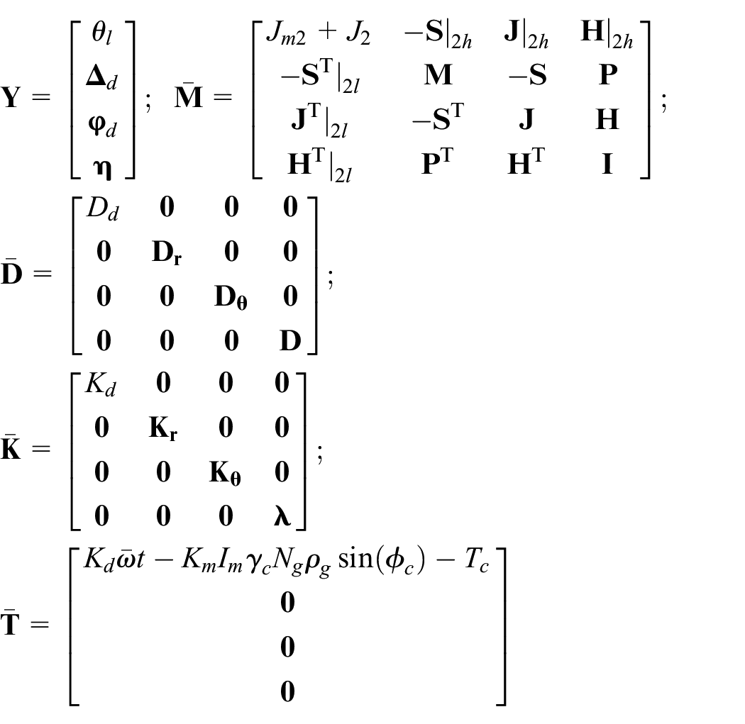
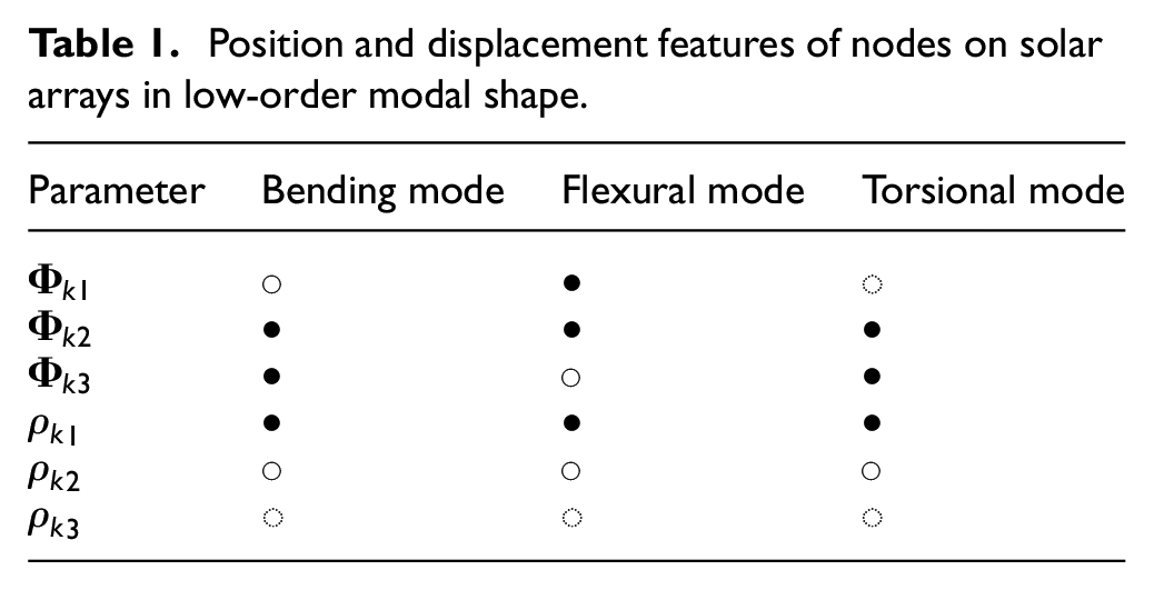
Further, equation (20) can be expressed in matrix form

where the three matrices on the left side of equation (21), respectively, correspond to generalized mass, damping and stiffness parameters.
Because

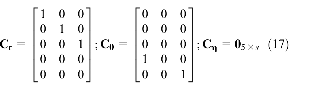
According to the equation of motion in equation (1), the five degrees of freedom are constrained, and equation (22) can be arranged as

where
Effect analysis of vibration reduction device
The equivalent dynamic-characteristic analysis model of SADS with VRD is deduced based on established dynamic model, and then the coupling relationship of VRD and dynamic characteristics of SADS is discussed. The effect analysis of structural coefficients of VRD on dynamic-characteristic parameters of twisting and bending deformation modes according to this model is carried out.
Equivalent dynamic-characteristic analysis model of SADS
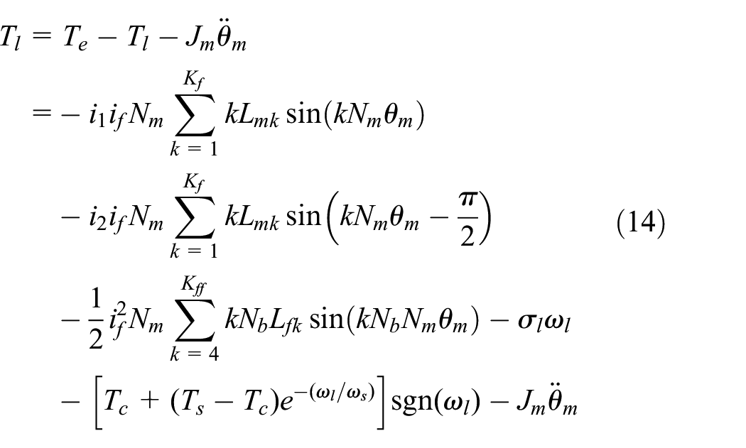
According to Zhu et al., 38 the drive torque in steady state can be written as

where Kd is the approximate stiffness of SADA. 39 Substituting equation (24) into the system dynamic model in equation (23), the simplified model can be expressed as

where each item in equation (25) is defined as
The influence of VRD on system dynamics resembles to a great extent the effect of a spring-dashpot elements with six-degree freedom on the root of solar array, as shown in Figure 3. Defining

Thereby the eigenvalue problem of SADS is transformed as the matrix eigenvalue problem of
Coupling-relationship discussion of VRD and dynamic characteristics of SADS
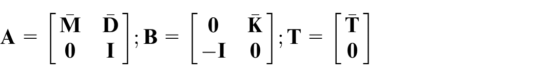
According to the construction feature of the researched solar array, the structure of solar arrays is in the plane of
Position and displacement features of nodes on solar arrays in low-order modal shape.
Modal momentum and angular momentum matrices,


Features of modal momentum and angular momentum components in low-order modal shape.

Based on the discussion about the modal momentum and angular momentum, there are some weak coupling relationships, thus the generalized mass matrix can be transferred to a diagonal partition matrix. In addition, the generalized damping and stiffness matrices are diagonal matrices, so they are also diagonal matrices after the same matrix transformation as the generalized mass matrix. Therefore, ignoring the small quantity in coefficient matrices, equation (25) can be written as

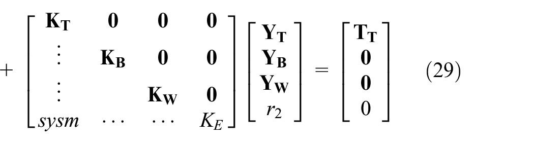
where subscript T, B, F, and E, respectively, represent torsion, out-of-plane bend, in-plane flexure, and other type vibration forms. It can be found through the above analysis and discussion that the coupling relationship between these three kinds of vibration form is relatively weak, which can be discussed separately in the ensuing sections.
Effect of structural coefficients of VRD on dynamic characteristics of SADS’s torsional modes
The dynamics equation about torsional modes of SADS was separated from equation (25) and theoretically solved, and then the effect of structural coefficients of VRD on dynamic characteristics of SADS’s torsional modes is analyzed in this section.
Analytic solution of eigenvalue problem
According to equation (29), separated torsional-mode dynamic equation is

The Laplace transformation form of equation (30) can be written as

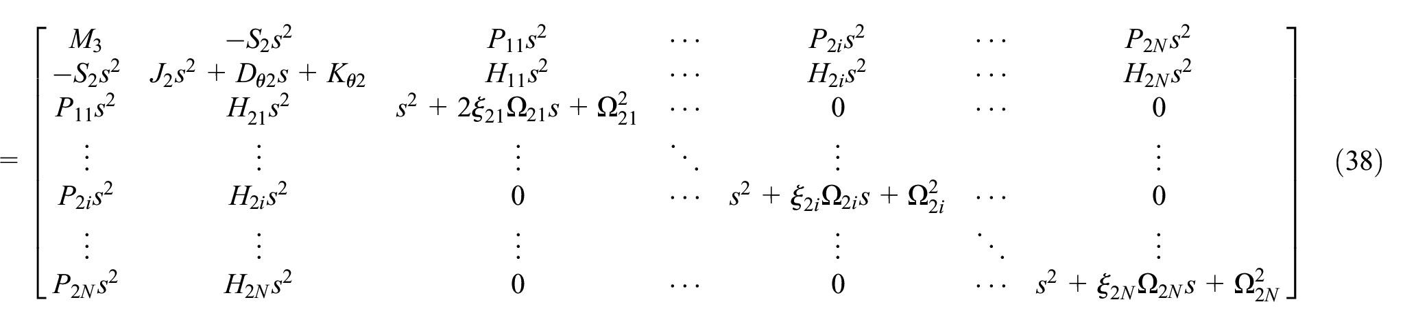
where the coefficient matrix yields

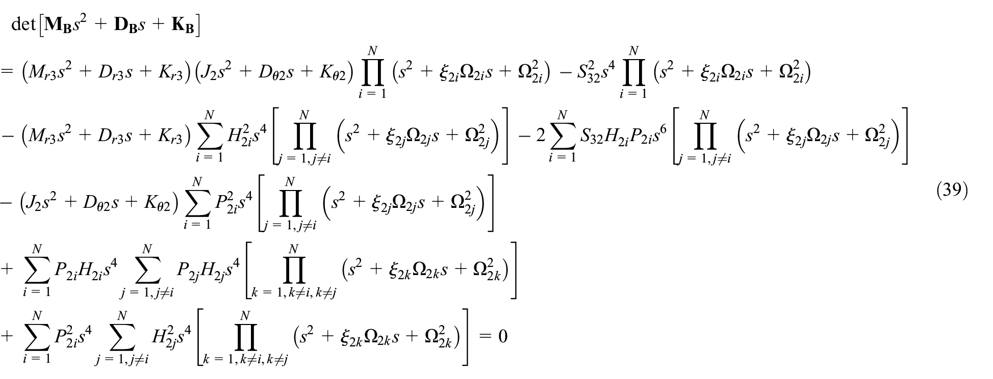
Thereout, the system eigenvalue problem is transferred into the following algebraic equation

The

Effect of structural coefficients of VRD on torsional mode
The equivalent parameters of VRD around the odyd axis becomes critical for attenuating the vibration in driving direction. At the very beginning of structure design, the relationship between the disturbance-exciting frequency and system natural frequencies should be determined. This section focuses on the influence analysis of equivalent parameters of VRD on dynamic characteristic of SADS, providing reference for the structure design of VRD. Figure 4 shows the relationship between system dynamic characteristics, such as natural frequencies and modal damping ratios, and the equivalent stiffness of VRD in driving direction, in which the equivalent damping of VRD is fixed at 1.0 Nms/rad. These natural frequencies rose with the equivalent stiffness of VRD, as shown in Figure 4(a). The maximum modal damping ratio is obtained at the minimum equivalent stiffness. The first modal damping ratio decreases with increasing equivalent stiffness of VRD at first and then maintain at 0.004. The second and third modal damping ratios keep stable in the boundaries of the interval of equivalent stiffness of VRD, and decrease within the middle range of the equivalent stiffness. In summary, the increase in equivalent stiffness of VRD can give rise to the low-order natural frequencies and reduce modal damping ratios, but the variation of the first-order dynamic characteristic parameter is greater than the higher-order modes.

Relationship between the odyd-axis torsional stiffness of VRD and modal parameters: (a) natural frequency and (b) modal damping ratio.
Figure 5 shows the relationship between dynamic characteristics of SADS and equivalent damping of VRD, in which equivalent stiffness of VRD is fixed at 100 Nm/rad. These three natural frequencies almost remain constant for additional increase in equivalent damping, indicating that these parameters are not sensitive to equivalent damping of VRD. On the other hand, there are progressive increases of the first three modal damping ratios with increasing equivalent damping. In summary, equivalent damping of VRD significantly affect the damping ratios, but not to the other observable dynamic characteristic parameters.
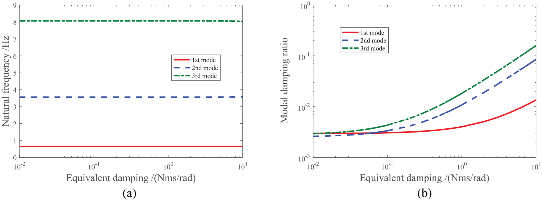
Relationship between the odyd-axis torsional damping of VRD and modal parameters: (a) natural frequency and (b) the modal damping ratio.
Effect of structural coefficients of VRD on dynamic characteristics of SADS’ bending mode
The dynamics equation about bending modes of SADS was separated from equation (25) and theoretically solved, and then the effect of structural coefficients of VRD on dynamic characteristics of SADS’s bending modes is analyzed in this section. Since the dynamic equation about in-plane flexural modes have the same form with that of out-of-plane bending modes, it will not be analyzed and discussed individually.
Analytic solution of eigenvalue problem
According to equation (29), separated dynamic equations about out-of-plane bending and in-plane flexural modes are


It is not difficult to find via comparing equations (35) and (36) that they share the same equation form with different parameter values, so the dynamic equation of bending modes is chosen as the example to analysis and discuss in this subsection. The following frequency-domain equation can be obtained by implementing the Laplace transformation on equation (35):

where the matrix of coefficient can be written as

Thereout, the system eigenvalue problem is transferred into the following algebraic equation
The

Effect of structural coefficients of VRD on bending mode
It is clear in equation (35) that components of VRD’s stiffness and damping round the odzd axis and along the odxd axis will affect the dynamic characteristics of bending modes. Figures 6 to 9 illustrates the relationship between structure parameters of VRD and modal features.
Relationship between odzd-axis torsional stiffness of VRD and features of bending modes: (a) natural frequency and (b) modal damping ratio.

Relationship between odzd-axis torsional damping of VRD and features of bending modes: (a) natural frequency and (b) modal damping ratio.

Relationship between odxd-axis translational stiffness of VRD and features of bending modes: (a) natural frequency and (b) modal damping ratio.

Relationship between odxd-axis translational damping of VRD and features of bending modes: (a) natural frequency and (b) modal damping ratio.
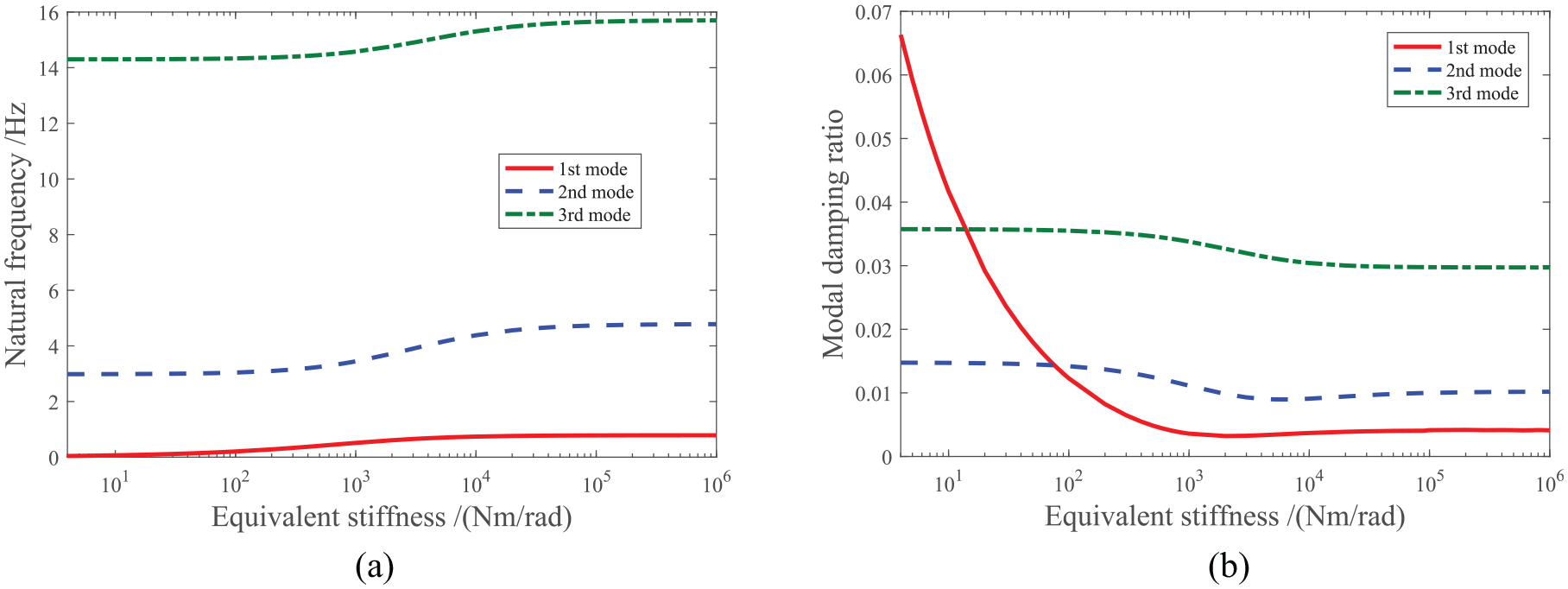
As seen in Figure 6, the first three natural frequencies increase obviously from 0.004, 2.983, and 14.300 Hz to 0.786, 4.780, and 15.700 Hz and reach stable in the rest stiffness range. The first modal damping ratio gradually decreases with the increase of the stiffness parameter of VRD. At 4 Nm/rad stiffness coefficient, the first modal damping ratio get the maximum value, 0.0663, which is obviously increased before uninstalling VRD. The minimum of the first modal damping ratio, 0.003, corresponds to 2000 Nm/rad stiffness coefficient. The second and third modal damping ratio change slowly when the stiffness coefficient is relatively small, and then decreased in a certain stiffness range and reach stable at the high stiffness range.
As seen in Figure 7, the first three natural frequencies basically remain unchanged in the observed damping range, indicating that the damping coefficient of VRD has little effect on the natural frequency. However, the first three modal damping ratios increase with the damping coefficient of VRD, and the increase rate of the first three modal damping ratios also increases gradually. The first modal damping ratio increases most obviously, and the third mode damping ratio always increases most slowly.
As seen in Figure 8, the change trend of the first three natural frequencies with the odxd-axis translational stiffness is basically the same as that related to the odyd-axis torsional stiffness but with a more obvious change amplify in the case of change trend. For instance, the second and third natural frequencies can be up to 4.772 and 15.650 Hz, respectively. The first modal damping ratio equals to 0.106, corresponding to 4 N/m stiffness coefficient, and then gradually decreases with the increasing stiffness of VRD until 100 N/m stiffness coefficient to get stable. The second and third modal damping ratios change slowly in the observed equivalent stiffness range. The steady values of these three modal damping ratios are 0.005, 0.010, and 0.030 respectively.
As seen in Figure 9, the first order natural frequency is not sensitive to the odxd-axis translational damping of VRD, and the relative variation is less than 2% in the studied range. The first three modal damping ratios increases with the odxd-axis damping coefficient of VRD. The first modal damping ratio increases almost linearly, namely, the rate of increase is constant. However, the larger the equivalent damping of VRD, the faster the other two modal damping ratios increase. The first modal damping ratio is the largest (up to 1.250), and the third mode damping ratio is the smallest (only 0.057).
Structure design of the elementary prototype of VRD
According to the above summing-up, the operation disturbance and residual vibration can be comprehensively suppressed via reasonable structural design of the VRD. On the one hand, using SADA parameters listed in Table 3, the harmonic excitation frequencies are integer multiples of 0.21 Hz. The first torsional natural frequency of a practical SADS is 0.635 Hz, very close to the third harmonic excitation frequencies, 0.63 Hz. Consequently, adjusting this first torsional natural frequency is beneficial in reducing the resonance response. On the other hand, the damping time for the first bending mode of solar array can be calculate as follows:

where
Parameters of the direct solar array drive assembly.

In order to neatly adjust the equivalent parameters, the structural configuration of VRD is divided into two parts: a central shaft with high axial stiffness is primary used to regulate the overall stiffness, and a damping ring with large structural loss factor and distribution area is selected to improved damping performance. As shown in Figure 10, the central shaft consists of the top and bottom connection interfaces and the uniform-section columnar structure. The central shaft is a replaceable component with different axial cross-sectional shapes to meet requirement for different equivalent stiffness. In comparison with circular, ring, and rectangle cross sections, the star section is selected in this work, because it is characterized by more variable parameters that is convenient to the adjustment of equivalent stiffness, as shown in Figure 10(b). The cyclic annular configuration in Figure 11 can ensure that the damping ring deforms uniformly and obviously under axial and lateral excitations, facilitating the improvement of equivalent damping.

Configuration of the stiffness-regulation central shaft: (a) stereoscopic view and (b) cross-section.

Configuration of the damping ring.
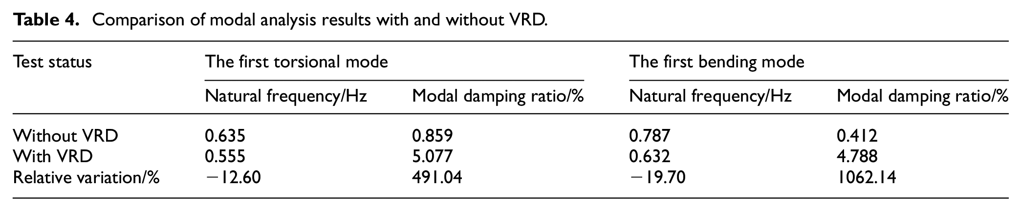
The elementary prototype and assembly relationship of VRD is shown in Figure 12. The perforated top and bottom coverings, in favor to replace the central shaft conveniently, bond with the damping ring with inner surfaces, and are installed with SADA and solar array with outer surfaces. Desired equivalent stiffness and damping can be achieved via reasonably design of the aluminum-alloy center shaft and the silicone-rubber damping ring. After repeated adjustments, the axial length of the center shaft is determined as 30 mm; the side length and thickness of cross-section of the center shaft is unified as 8 and 2 mm, respectively; the inside and outside diameters of the damping ring is 110 and 150 mm, respectively. Its mass is merely 1.169 kg, and maximum shape envelope is Φ156 m × 56 mm. Complex modal analysis results of solar array with and without VRD are given in Table 4. After the installation of VRD, the first torsional natural frequency becomes 0.555 Hz, obviously staggering the disturbance frequency, and the corresponding modal damping ratio raises 491.04%. The modal damping ratio of the first bending mode can be increased more than ten times, while the natural frequency can only be reduced by 19.70%.

Structure configuration of VRD: (a) stereoscopic view and (b) decomposition chart.
Comparison of modal analysis results with and without VRD.
The experiment validation for the effectiveness of VRD
In order to evaluate the effectiveness of the presented VRS on suppressing the axial operation disturbance induced by the tracking-sun drive and the bending residual vibration caused by the attitude adjustment, the disturbance characteristic and dynamic modal experiments were implemented.
Validation experiment on operation disturbance suppression
Experiment system
Experiment object contains SADA, flexible appendage and VRD, as shown in Figure 13. The flexible appendage, utilized to imitate the mass and stiffness characteristics of solar array in the drive direction, is designed by adjusting structure size to meet the equivalence requirement in the moment of inertia (18 kgm2) and base frequency in clamped boundary (0.18 Hz). In addition, a gantry and lifting attachments are equipped to unload the gravity of SADS along the rotation axis. Figure 13(b) to (e) show SADA, VRD, and connection devices of SADA and the flexible appendage, respectively. These connection devices connect SADA, VRD, and the flexible appendage rigidly.
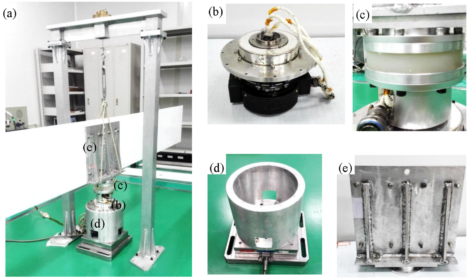
Structure composition of the experiment object: (a) experiment object, (b) fixture of SADA, (c) SADA, (d) VRD, and (e) fixture of the flexible appendage.
The disturbance characteristic experiment system is composed of the six-degree-of-freedom force measuring platform, laser vibrometer (including the sensor and processor), signal amplifier, data acquisition unit, the controller of SADA and computer, as shown in Figure 14. The six-degree-of-freedom force measuring platform connects with SADA, and is used to measures the disturbance force and torque. The type of the force measuring platform is Kistler 1255CQ01. Its accuracy for force and torque measurement are 1 × 10⁻³ N and 1 × 10⁻³ Nm, respectively; and the measurement ranges are 0 N∼1 × 100 N and 0 Nm∼1 × 100 Nm, respectively. The type of the laser vibrometer is Polytec PSV-500. The direct measure quantity of the laser vibrometer, however, is the linear velocity of the measuring point arranged on the rigid connection device of the flexible appendage. The linear-velocity measurement range is 1 × 10⁻⁶ m/s∼1 × 10−1 m/s. Because drive speed is very small, only 0.0635°/s, the angular velocity of the flexible appendage is proportional to the linear velocity in short time via ignoring the distance change of measuring point respect to the rotation axis, the laser vibrometer can be used to obtain the angular velocity of the flexible appendage. The signal acquisition unit (Kislter 5080) of the force measuring platform and the processor of the laser vibrometer are used to acquire and process the force and torque data and velocity data, respectively. The signal amplifier is combined with the external controller of SADA, to provide pulse commands which control the drive speed of SADA. The measure data are transferred to the computer, and the LMS test analysis software is used to analyze measure data in time and frequency domain.

Experiment system for the disturbances characteristic of the solar array drive system.
Experiment method
The sampling frequency of the data acquisition unit is 1024 Hz. the drive control of SADA is divided into three parts: the motion of the flexible appendage is suspended in 0–30 s; the drive speed is set as +0.0635°/s in 30–130 s; the rotation motion is also suspended in 130–150 s, as shown in Figure 15. Since the magnitude of the vibration response of SADS is very low, one holding command is arranged before measuring disturbance to assess the effect of the environmental noise on the measure data. In addition, another holding command, following the end of constant-speed command, is used to record the residual vibration response which can be the data foundation for the identification of system base frequency. The trend in measurement quantities needs to be eliminated by data pre-processing method, and then Fourier transform is employed to obtain corresponding frequency-domain data. The characteristic parameters of the dynamic response, such as the fluctuation range and mean square deviation of disturbance torque, the response peak in the frequency spectrum as well as corresponding frequency value, are extracted. The experiment repeatability can be validated by comparing the measurement data of the three repetitive experiments in same state.
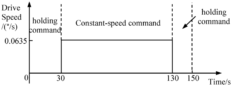
Profiles of the drive speed in different experiment stages and corresponding drive commends.
Discussion on the experiment results
The experiment data before and after the installation of the VRD is analyzed to assess the performance of VRD in terms of disturbance suppression. Disturbance torque undergoes four different stages (as shown in Figure 16): the first stage (0–30 s) is static state, in which measuring equipment record the environmental noise; the second stage (30–60 s) is starting state, which is a period of transition between static state and stable state; the third stage (60–130 s) is stable state, in which steady-state response characteristics of SADS can be obtained; the fourth stage (130–150 s) is stopping state, which provides the data foundation for identifying the base frequency of SADS.

Experiment results of disturbance torque of the solar array drive system.
The data analysis focuses on the stable-state response within the time range of 110–130 s, as shown in Figure 17. Disturbance torque is characterized by periodic fluctuation, in detail, the combine of the main low-frequency fluctuation and several small-amplitude high-frequency fluctuations. With the function of VRD, the fluctuation amplitude before the installation of VRD is damped obviously. In addition, disturbance spectrums both contains one significant low-frequency peak, corresponding to 0.625 Hz (without VRD) and 0.563 Hz (with VRD), and the peak without VRD is significantly higher than that with VRD.

Stable-state disturbance torque before and after the installation of VRD: (a) time history and (b) frequency spectrum.
Table 5 lists response parameters, such as fluctuation ranges and mean square deviation of the steady-state disturbance torque, average angular velocity and frequency corresponding to the spectrum peak. Fluctuation amplitudes of disturbance torque before and after installing VRD are 0.552 and 0.322 Nm, respectively, implying a 41.61% decrease. Similarly, the mean square deviation of disturbance torque is also reduced from 15.567% to 7.241% with 53.48% of disturbance suppression performance. The base frequency becomes 0.563 Hz, keeping away from the third-order cogging torque frequency (0.63 Hz). In addition, it can be found by comparing with Table 3 that the base frequency obtained by theoretical analysis is in good agreement with experimental results.
Comparison of experiment results before and after installation of VRD.
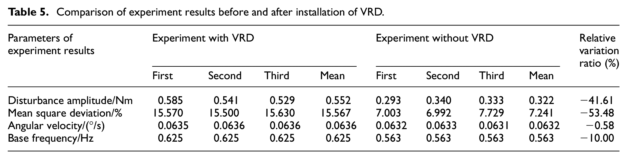
The reciprocating fluctuation is observed in the steady-state angular-velocity profile of the flexible appendage, as shown in Figure 18(a). After installing VRD, the phenomenon of negative angular velocity can be observed. The reason is that VRD is located between SADA and the flexible appendage, weakening the connection stiffness. Consequently, the angular velocity of the flexible appendage is simultaneously affected by the rotation of SADA and the deformation of VRD. The negative angular velocity is possible when the deformation of VRD increases. However, the deformation of VRD is recoverable, thus its effect on the average angular velocity is negligible within a long period (as listed in Table 5). The angular-displacement profile with VRD resembles to that without VRD despite existing instantaneous negative angular velocity, as shown in Figure 18(b). In summary, the installation of VRD has little influence on the long-term orientation accuracy of the solar array.
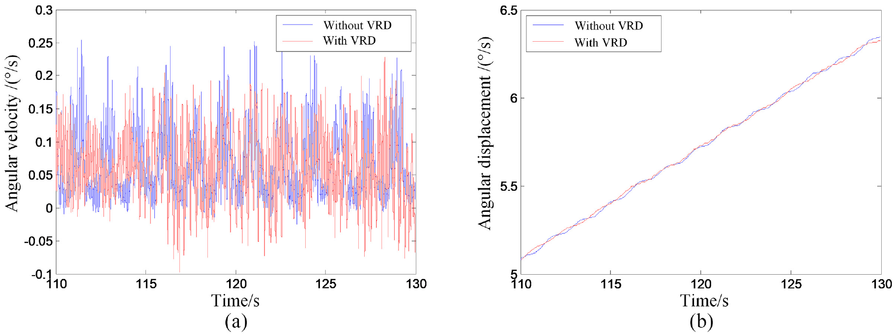
Rotation motions of the flexible appendage before and after the installation of VRD: (a) angular velocity and (b) angular displacement.
Validation experiment on modal damping ratio of bending modes
Experiment system
The experiment object is composed of VRD and a solar array simulator, which is made of a triangle support and one rectangular carbon-fiber composite sandwich panel sharing the same materials and size with the practical solar array. The VRD is installed between the triangle support and the fixed wall. The sandwich panel is overhung by the gravity unloading device to eliminate the influence of gravity. Because this experiment is implemented in the atmospheric environment, the atmospheric damping effect is inevitable. The measurement system consists of the electromagnetic actuator, force sensor, acceleration sensors, charge amplifier, data acquisition unit, computer and other hardware equipment, as well as the modal test and analysis software, as shown in Figure 19. The B&K Pulse modal test software generates the excitation signal and realizes the processing of measurement data; The B&K 2732 charge amplifier can amplify the excitation signal and provide it to the electromagnetic actuator; The B&K 4824 electromagnetic actuator is used to generate excitation force, and its force range is 0–220 N; The B&K 8230-001 force sensor is mounted between the electromagnetic actuator and the solar array to measure excitation force. There are 12 acceleration sensors, B&K 4574-001, mounted on the solar array and used to measure the vibration response; the acceleration sensitivity is 200 mV/g and the measurement range is 0–10 g. The B&K 3050-A-060 signal acquisition unit with 13 channels is used to acquire force and acceleration data. The modal analysis software, B&K Reflex, identificates the modal parameters based on measurement data of excitation force and acceleration response.
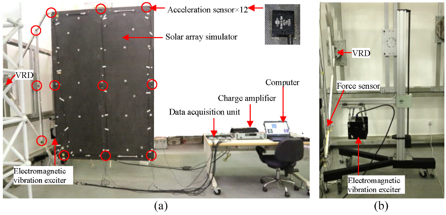
Modal experiment system of the solar array: (a) front view and (b) side view.
Experiment method
Modal experiment was carried out by single-point force excitation and multi-point acceleration measurement. The modal test software generates a random excitation signal within 0–12.5 Hz outputting to the electromagnetic exciter through the charge amplifier. The excitation point is selected at the tripod of the solar array. The sampling frequency is 400 Hz. The orthogonal polynomial method is employed to identificate modal parameters. The mode shape is normalized by taking the maximum value in the mode shape vector as 1.
Discussion on the experiment results
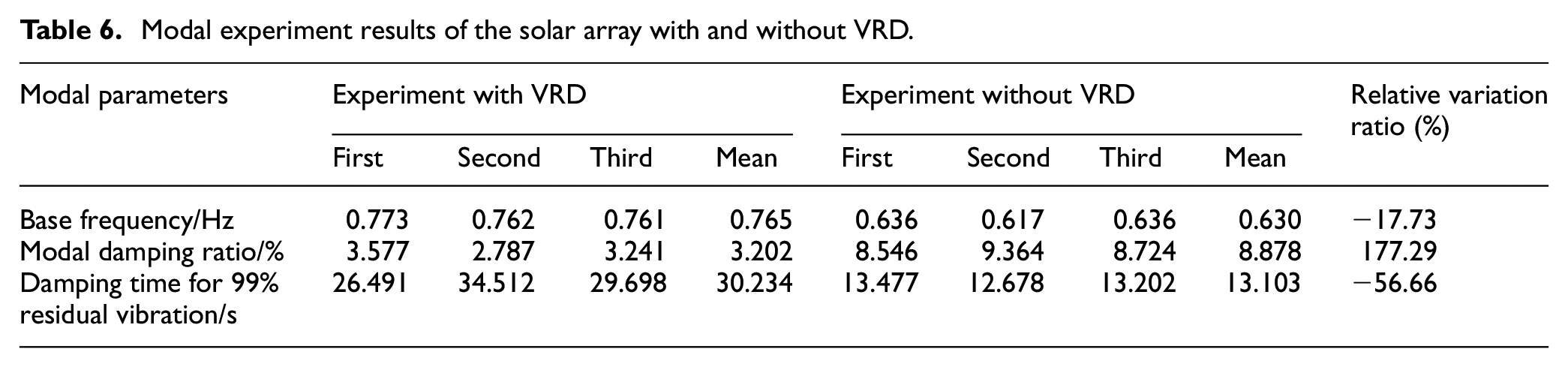
Modal experiments were carried out repetitively for the solar array with and without VRD, and the frequency domain modal identification method was used for the data processing after each experiment to get the natural frequency and modal damping ratio of the first bending mode, as shown in Figure 20. By installing VRD, the base frequency of solar array decreases from 0.765 to 0.630 Hz with about a 18% reduction illustrating the structural stiffness is weakened. Moreover, the modal damping increases significantly from 3.202% (including air damping) to 8.878% (including air damping), with a 177% increase because of the function of VRD, indicating the great damping contribution of VRD to solar array. The damping time of 99% vibration-amplitude are respectively 29.893 and 13.103 s for solar array without and with VRD. That means a 56.17% relative decrease in the damping time can be carried out for the function of VRD. In addition, it can be concluded according to Table 6 that the whole modal experiment results have good repeatability. 99% of the residual vibration is reduced means that the residual vibration is reduced by two orders of magnitude. The damping time for reducing 99% residual vibration, Td(99%), can be obtain based on equation (42) by making

The first modal shape obtained via modal parameter identification obtained from the first test: (a) without VRD and (b) with VRD.
Modal experiment results of the solar array with and without VRD.
Moreover, the measured natural frequency of the first bending mode is very close to the theoretical analysis result, but the influence of air damping on the modal damping ratio result cannot be excluded due to the test in atmospheric environment, so the modal damping ratio obtained by the experiment is significantly greater than the theoretical analysis result, as listed in Table 7. However, it is not difficult to find that the variation tendency and amplitudes of modal damping ratio before and after the installation of VRD are in good agreement. In addition, the relative error of the natural frequency is less than 3%, and the correctness of the analysis model can be verified.
Model parameters comparison between theoretical analysis and experiment measure.

Since there is no air damping effect in space environment, it was not considered in the theoretical analysis. However, the air damping is inevitable in laboratory test. The different of environmental damping conditions make the modal damping ratio and damping time obtained by analysis and test cannot be directly compared. Because of the function of air damp, the damping time obtained by theoretical analysis are greater than the experiment result, and the decrease amplitude of damping time related to the theoretical analysis is more obvious. Thus, the effect of VRD on the damping time in practical space applications is greater than that in laboratory environment.
Conclusions
The operation disturbance induced by the solar array drive system and the residual vibration of solar array following the attitude adjustment are characterized by distinct vibration categories and modal shapes. In order to attenuate these two kinds of vibration disturbance systematically, a multi-degree-of-freedom vibration reduction strategy combining frequency adjustment and damping was presented, and the theory modeling, influence analysis, device design and performance testing for this vibration reduction strategy were implemented. The kernels are as follows:
This VRD, composed of replaceable central shaft and fixed damping ring, is suggested to be assigned between solar array and its drive mechanism, which is beneficial in adjusting the natural frequency and increasing modal damping ratio of SADS simultaneously.
The equivalent stiffness of VRD is critical to the natural frequency of SADS and should be carefully deliberate to avoid resonance, however, only the equivalent stiffness within a specified range is insensitive to the natural frequency.
The equivalent damping of VRD always have positive correlation with modal damping ratios, thus the damp material with high loss factor is suggested in structure design of VRD to accelerate the damping speed of the residual vibration of solar array.
The system dynamics model developed in this work is valid, and experimental and analytic results are in well agreement with less than 10% of relative error.
A good performance up to 40% in terms of operation disturbance suppression and a greater than 56% decrease of the damping time for 99% residual vibration have been obtained experimentally.
Footnotes
Acknowledgements
The authors would like to thanks the technical assistance on the dynamic experiment from the Beijing Institute of Control Engineering and Science and Technology on Space Intelligent Control Laboratory.
Handling Editor: James Baldwin
Declaration of conflicting interests
The author(s) declared no potential conflicts of interest with respect to the research, authorship, and/or publication of this article.
Funding
The author(s) disclosed receipt of the following financial support for the research, authorship, and/or publication of this article: The financial support of the National Natural Science Foundation of China (Grant No. 11272348) is acknowledged.