
Abstract
The application of vertical axis wind turbine is suitable in a low wind speed environment. Nevertheless, vertical axis wind turbine with kenaf turbine blade will promote an additional green concept by utilising biocomposite materials. The innovation in turbine blade via macro-fibre composite as structural health–monitoring system and micro-energy harvester can enhance the vertical axis wind turbine technology application. Hence, this research’s objective is to evaluate the factors influencing the performance of micro-energy harvester and to assess the feasibility of structural health–monitoring application in biocomposite turbine blade. There are two methods to attach the macro-fibre composite used in this study, which are surface bonded and embedding into the turbine blade. Vibration simulation experiment and modal testing approach are conducted on the kenaf turbine blade, and further analysis was performed via the Taguchi statistical analysis to determine the factors affecting the micro-energy harvester and structural health–monitoring performance. The results show that by bonded to the surface as proposed is the best technique in promoting higher micro-energy harvesting at the vibration range of 10–90 Hz. Furthermore, the structural health–monitoring system was proved to operate simultaneously with the micro-energy harvesting system in turbine blades.
Introduction
The application of vertical axis wind turbine (VAWT) in wind energy generator has created advantages in several aspects such as free wind direction oriented, the ability to be towerless and huge power density per square metre. 1 However, the material of turbine blades has raised concerns. The applications of synthetic fibres like glass fibre and carbon fibre in turbine blades have promoted several disadvantages such as risk of inhalation during the fabrication process, renewability, biodegradability and recyclability issues. The usage of biocomposite fibre to replace synthetic fibre as reinforcement in fibre-reinforced plastics (FRPs) is beginning to become widespread. 2 Investigations in biocomposites have lead to several types of natural fibres such as flax,3,4 bamboo, 5 pineapple, 6 jute,7,8 and kenaf.8–11 The mechanical properties in natural fibre may differ due to several factors such as fibre morphology, structure density, cell wall thickness, woven or non-woven, 12 length and diameter of the structure. 13 Kenaf fibre is one of the natural fibres that is extensively researched and has given significant findings for future benefits.12–16
Besides that, the application of structural health–monitoring (SHM) system in turbine blade is becoming very important. In order to employ the SHM system, the dynamic characterisation of mechanical system on turbine blade should be determined as well. Modal analysis is a common way of testing, which is conducted to study the natural frequency, mode shapes and damping percentage of a structure. 17 One of the SHM sensor devices is macro-fibre composite (MFC). It can respond as a sensor and micro-energy harvester as well. The flexibility features make it very suitable to bond on the big and vibrating structures, also in addition to its high electromechanical coupling coefficient. 18 Besides, it solves several issues highlighted in monolithic piezoelectric transducers such as mechanical stability of the piezoelectric transducer under huge stress, brittleness, 19 electrical breakdown of the material under high fields and reduction in efficiency due to dielectric losses and depolarisation. 20 MFC type d31 is proposed, as it produces a large strain and more energy for small applied forces. 21 Moreover, MFC can produce electrical power up to 65% of input mechanical energy, better performance due to its thin layer and are classified as a bimorph structure which generates double output as compared to a unimorph structure. 21
The micro-energy harvester reacts from the vibrations occurring in the structure body. This concept is applied in several research and innovation technologies20,22,23 and has shown promising results. The factors influencing the amount of harvested energy are piezoelectric material, proof mass, gap of interdigitated electrodes, overlapping effect of resonance frequencies and operating mode of piezoelectric conversion.24,25 Theoretically, this effect can be further described via the equivalent linear spring mass system (Figure 1) and equations (1)–(3)

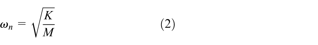
where z = x–y is the net displacement of mass, M is the lumped mass, K is the spring constant, C is the damping coefficient, and
where m is the seismic mass,

Cantilever beam with tip mass. 25
Most findings showed that the MFC is bonded only on the surface of the structure.18,26,27 Hence, the combination of MFC in turbine blades could give new insights into, especially, the effect of bonded MFC on the turbine blades. Thus, the objective of this research is to investigate the bonded MFC effect technique on woven kenaf wind turbine blade for micro-energy-harvested VAWT application and to assess the feasibility of SHM application in woven kenaf turbine blade in VAWT system.
Experimental setup
Wind turbine fabrication
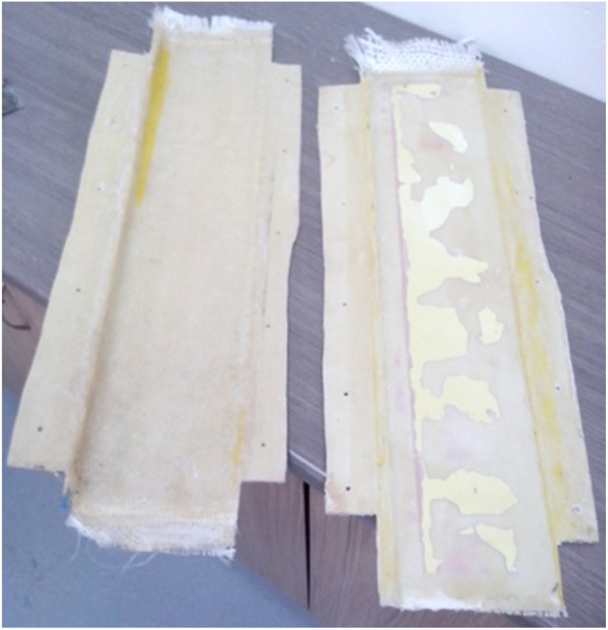
The wind turbine blade was fabricated via a vacuum infusion process. The mould was fabricated in the laboratory following the characteristics of NACA 0018 design specification. The complete mould is shown in Figure 2. A woven kenaf, which is 3 × 11 yarn for each 1 cm2 utilising 300 Tex yarn, was selected as shown in Figure 3. The woven kenaf was stacked in three layers as shown in Figure 4.
Top and bottom mould of turbine blade.
Schematic of kenaf woven orientation: (a) Orientation A and (b) Orientation B.

Sample 1: Orientation A/A/A.
There are two techniques used to bond the MFC patch. For the first technique, the MFC patch was embedded inside the turbine blade. The other technique was onto the turbine blade where the patch was bonded on the surface by assuming that the bonding is effectively adhered so that the stress is effectively transferred between two surfaces.
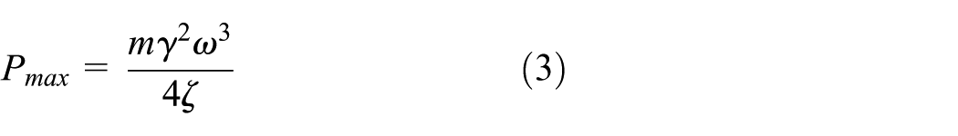
In the fabrication process, the ratio between kenaf and epoxy resin is 30:70, and it was cured for 12 h. The epoxy employed in this research is EpoxAmite 100 (Smooth-On) and 102 Medium Hardener (Smooth-On). The resin was prepared at a combination of epoxy to hardener, 100:28.4 g as recommended by the manufacturer. In order to reduce cost, weight and manufacturing process time, the blades were fabricated in half design and became one plate as shown in Figure 5. After curing, the part was taken out and cut into the required dimension.
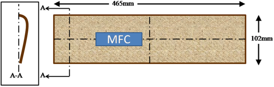
The schematic picture of turbine blade design and MFC location.
The MFC patch was embedded approximately near to the centre line of the turbine length and width as shown in Figure 5. In this research, the location was selected for the fabrication and assembly convenient. The research on MFC location optimisation can be conducted in the future. The MFC was properly laid between the kenaf layers as shown in plate fabrication.
The MFC was embedded and bonded at the same location of the woven kenaf turbine blade. After the curing process, a second MFC was bonded at the same place of the embedded MFC located, as shown in Figure 6. Hence, the data collection could be compared thoroughly. Four kenaf blades were fabricated to be assembled in the wind turbine system prototype, as shown in Figure 7. The blade containing the MFC patch was employed for micro-energy harvesting in wind turbines.
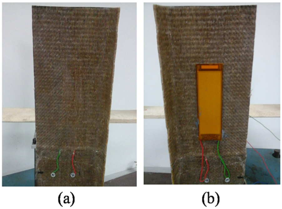
Woven kenaf turbine blade: (a) embedded MFC location and (b) bonded MFC located at same place of embedded MFC.
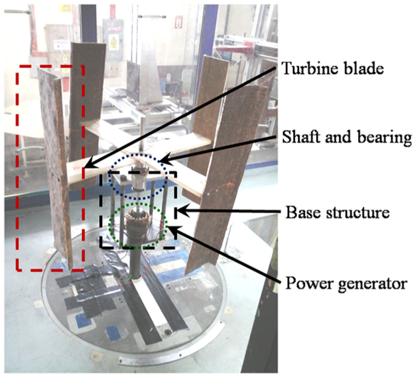
Segment in wind turbine system.
Micro-energy harvester testing
A vibration test for turbine blades was conducted on the wind turbine prototype. The wind turbine was fixed, and the respective turbine blade was exerted by a shaker at a frequency range from 10 to 100 Hz. The range was proposed by assuming that the first mode occurred in that range. This test only gave attention to the first mode of turbine blade. The same methodology as the vibration test on plates was employed to this testing. The experiments were repeated six times, and each experiment was conducted for 10 s. The MFC was randomly located in layers, as this research focuses to determine the bonded MFC technique effect and material optimisation. The experimental setup is shown in Figure 8. Further investigation on the MFC was conducted for SHM application.

Experimental setup for micro-energy harvesting testing on wind turbine system prototype.
SHM identification for turbine blade via modal approach
The SHM test was conducted to determine the pattern of frequency-response function graph between embedded and bonded MFCs as well as between damaged and undamaged turbine blades. This experiment was conducted as a preliminary study regarding the SHM system on kenaf turbine blades, since the main focus of this research is on micro-energy harvesters. In order to simulate damaged turbine blades, the blade consisting of MFC patch was drilled at the tip blade as shown in Figure 9.

Turbine blade: (a) normal condition and (b) damaged condition.
The experiment equipment was prepared into two sections, which were vibration exciter and data collector. The vibration exciter includes equipment such as shaker, amplifier and vibration controller. While for the data collector, MFCs as sensor and oscilloscope were employed. The integration between vibration exciter, data collector and wind turbine system were set up as shown in Figure 10. The tip of the shaker was touched to the free end of the plate to simulate the vibration at the respective ranges of frequency.

Experimental setup for structural health–monitoring system identification.
The SHM identification was set up following the modal approach and vibration concept as conducted by Sodano et al., 20 Ali and Ibrahim 21 and Wang. 28 As the objective is only to determine the pattern graph of frequency-response function, the analysis was only limited to data comparison between embedded and bonded MFCs as well as damaged and undamaged turbine blades.
The shaker vibrations were set at a range of 10 to 100 Hz. The amplifier was set at 2 W. The shaker frequency and amplitude was controlled by a frequency controller and amplifier, respectively. The shaker frequency was set at 10, 20, 30, 40, 50, 60, 70, 80 and 90 Hz. It operates at a bandwidth of 100 Hz, a spectral line equal to 1024 at 0.097 Hz resolution and acquisition time of 10.24 s. The shaker vibration was set to excite in burst sine signal.
The experiment started with the normal turbine blade for bonded and embedded MFCs. Then, the turbine blade was drilled and the procedure was repeated for the damaged turbine blades in bonded and embedded MFC conditions. The voltage induced from MFC was transmitted to a smart power-harvesting module (EH-CL 50 from smart material) before being connected to an oscilloscope for voltage recording. The spectrum data were set similar to the shaker spectral line, which was 1024. The voltage root mean square (RMS) was recorded via the oscilloscope (PICOSCOPE) and analysed in PICOSCOPE software. It was displayed in a frequency-response function graph by employing a flat-top window function. The flat-top windows function calculated the data from time-domain function to frequency-response function. The flat-top function offered low errors as compared to other functions. Logarithmic unit (dBV) was employed in describing the magnitude of each frequency. Further analysis via Taguchi method was employed from the experimental data.
Statistical analysis via Taguchi method
Taguchi methods are statistical methods initially developed by Genichi Taguchi to improve the quality of manufactured goods. More recently, the techniques are used in scientific and engineering experiments, since they allow for the analysis of various parameters without a prohibitively high amount of experiments. Many researchers nowadays apply robust design as a tool to achieve quality engineering in many fields.
Furthermore, Taguchi offers an experimental design totally based on statistical design as a tool, which is less sensitive to noise factors. Two major tools used were: signal-to-noise (S/N) ratio, which measures quality with emphasis on variation, and orthogonal arrays, which accommodate many design factors simultaneously. The significance of the factor or multiple factors that affect the machining quality performance could be determined in a very short time when this technique is employed.
The method of calculating the S/N ratio response was designed in three different modes depending on whether the quality characteristics is smaller the better, larger the better or nominal the better. 29 In this analysis, the larger the better was preferred to perform high energy. The equations for calculating the S/N ratio were for the larger the better characteristic (in dB), which was

where n is the number of observations, and
The degree of predictable performance of a product or process in the presence of noise factors could be defined from the S/N ratio values. For each type of characteristics, with the above S/N ratio, the higher the S/N ratio, the better the result. The S/N ratio was presented in response graph and response table.
In the micro-energy harvesting analysis on turbine blade prototypes, experiments were conducted at L14 orthogonal array. Two factors were employed with two levels and three levels in each factor as shown in Table 1. Voltage RMS was the output for this analysis.
Taguchi experimental parameter for micro-energy harvesting analysis on turbine blade prototype.

Results and discussion
Figure 11 shows the voltage RMS result on micro-energy harvesting from turbine blade prototypes. Bonded MFC demonstrated higher value than embedded MFC. The average result for bonded MFC in the range from 10 to 100 Hz was 117.3 mV. Meanwhile, the average result for embedded MFC was 26.2 mV. Bonded MFC showed a 348% increment as compared to embedded MFC. This shows that the bonded MFC performs better than the embedded MFC in harvesting energy.

Voltage RMS result in micro-energy harvesting on prototype of wind turbine.
The bonded MFC type performs better, which corresponds with previous 30 reports. The MFC performance depended on the distance of MFC layer from the neutral axis of the structure. Theoretically, the strain is increased with the increment of the distance from neutral axis. The comparison between embedded and bonded MFCs corresponded between experiment and statistical analyses. The bonded MFC was proposed as the best selection to harvest higher micro energy. The results were further analysed via Taguchi statistical analysis.
Taguchi statistical analysis for micro-energy harvesting of turbine blade prototypes
A statistical analysis on micro-energy harvesting of turbine blade prototype is presented via response table and response graph in Table 2 and Figure 12, respectively. Table 2 shows that the bonded type is the most significant factor influencing the results of voltage RMS in turbine blades. Meanwhile, Figure 12 exhibits that the optimum parameter to achieve higher voltage RMS is a combination of MFC bonded to turbine blades.
Response table for S/N ratio in micro-energy harvested of turbine blade prototype.

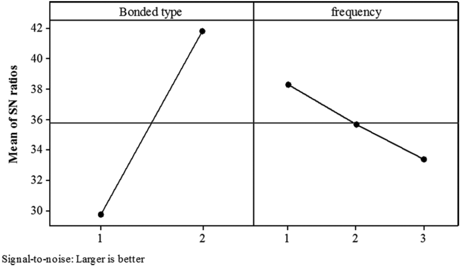
Response graph for S/N ratio in micro-energy harvesting of turbine blade prototype.
The results show a comparable finding with plate vibration testing, which proposed bonded MFC as the best parameter. Figure 12 exhibits that the frequency factor was proposed at the lowest frequency level. It can be predicted that the natural frequency of the turbine blades occurred at a lower range of frequency.
SHM identification for turbine blades via modal approach
This experiment was conducted to achieve the objective of a fundamental assessment of the SHM in kenaf wind turbines. The results are limited to pattern recognition between damaged and normal blades for bonded and embedded MFCs as shown in Figure 13. The comparisons of frequency-response function graphs between damaged and normal blades are exhibited in Figure 14 for bonded MFC and Figure 15 for embedded MFC.

Comparison of frequency-response function graph between damaged blade embedded MFC, normal blade embedded MFC, damaged blade bonded MFC and normal blade bonded MFC.

Comparison of frequency-response function graph between normal and damaged blade from 10 to 90 Hz excitation from shaker in bonded MFC.

Comparison of frequency-response function graph between normal and damaged blade from 10 to 90 Hz excitation from shaker in embedded MFC.
Figure 13 shows the overall average magnitude (dBV) of bonded and embedded MFCs in normal and damaged blades. Generally, a normal turbine blade with bonded MFC illustrates the highest magnitude than damaged turbine blades with bonded MFC. Similar to embedded MFC, normal blades exhibit a higher magnitude than damaged blades. This indicates that the SHM system can perform well and work in the kenaf wind turbine blade system. The findings in bonded MFC of normal blades support the previous experiment results, which showed the highest magnitude in induced electricity throughout the range of experiments. Embedded MFC exhibited a lower magnitude than bonded MFC. This report agreed with vibration tests on the turbine blade and verified that bonded MFC performed better due to the significant length from the natural axis. Besides that, it showed that damaged blades caused the magnitude response to reduce, hence assisting in identifying the structural integrity of the blade and proved that SHM is feasible in the kenaf wind turbine blade system.
The comparison graph between damaged and normal blades for bonded MFC
Figure 13 presents a comparison of frequency-response functions for bonded MFC between damaged and normal blades at different exciter frequencies. The normal blades result is presented in blue colour, while the damaged blade is illustrated in red colour. Generally, the normal blade shows a higher magnitude than the damaged blade in all figures. This behaviour shows that damage and normal condition can be predicted and determined via bonded and embedded MFCs especially in kenaf turbine blade application at an exciter frequency range from 10 to 90 Hz. Hence, it may assist the engineer to observe and monitor the structural integrity of the wind turbine system.
The graph peak in the frequency-response function is clearly illustrated in the graph at the exciter frequencies of 10, 20, and 30 Hz. Clear peak lines disappeared in other exciter frequencies. The noise from the ambient response and higher exciter frequencies may influence the emerging of peak points in each graph line. Furthermore, the peak lines for each graph for damaged blades decreased as compared to the normal graph. It may be due to changes in the natural frequency of the turbine blade as the weight was reduced.
Fundamentally, the SHM system can be employed via bonded MFC in the wind turbine system, and further analysis should be conducted to systematically understand the behaviours such as critical point, optimum layer thickness of blade and MFC location for better performance. Furthermore, the effect of embedded technique should be explored as well and will be presented in the next section.
Comparison graph between damaged and normal blades for embedded MFC
The comparison of frequency-response function graph for embedded MFC between damaged and normal blades is reported in Figure 15. The normal blade result is exhibited in blue colour, while the damaged blade is illustrated in red colour. Both normal and damaged graph lines showed a similar trend and overlapped for most exciter frequencies except for 30, 60, 80 and 90 Hz. The graph line in bonded MFC showed a clear difference between normal and damaged blades, but the difference in embedded MFC is small. However, as in the bonded MFC analysis, the damaged blade frequency magnitude was reduced as compared to the normal blade. Several factors may influence the frequency magnitude such as its location from the neutral axis, embedded MFC and damage distance.
On the other hand, the peak point analysis showed that the entire graph from each exciter frequency exhibited a clear peak line except for 80 and 90 Hz exciter frequencies. The normal blade illustrated a clear peak as compared to the damaged blades. From the observation and above discussion, embedded MFC demonstrated low sensitivity to the damage of the structure, as the frequency magnitude for normal and damaged blades showed almost the same trend, and at some points an overlap occurred. However, the peak trend in normal blades of embedded MFC as compared to bonded MFC showed that it responded highly with deformation due to external forces exerted on the turbine blade.
The SHM system in kenaf wind turbines is a feasible technique based on the experiments conducted. The signal basic behaviour for embedded and bonded MFCs was recorded but need further investigation. The bonded MFC performed well in differing damaged and normal blade signals as compared to embedded MFC, while embedded MFC showed high sensitivity with the external forces applied to the turbine blade.
Further investigation needs to be conducted to understand several factors influencing the system performance for SHM application such as the natural frequency behaviour of the structure, ambient effect to the signal noise, critical point of the turbine structure, optimum layer thickness of blades, MFC locations for better performance and damage distance.
Conclusion
The application of woven kenaf in wind turbine blades opens up new investigation, especially on micro-energy harvester by MFC. The MFC-bonded factor was deeply investigated to understand the behaviour influencing the performance of micro-energy harvester. Besides that, the application of SHM in biocomposite wind turbine blade was preliminary explored for future investigation.
Wind turbine micro-energy harvester testing and Taguchi analysis presented that the bonded technique was suggested as the most influenced factor in micro-energy harvesting at a vibration range of 10 to 90 Hz. Hence, bonded to the surface was proposed as the best technique in promoting higher micro-energy harvesting for woven kenaf turbine blades at a vibration range of 10 to 90 Hz. Besides that, the SHM system can be practically applied simultaneously with the micro-energy harvesting system in turbine blades.
Footnotes
Acknowledgements
The authors would like to thank Universiti Putra Malaysia for providing the Geran Putra – Inisiatif Putra Berkumpulan (GP-IPB) grant (grant no.: 9490602) for this research work.
Handling Editor: Sung-Cheon Han
Declaration of conflicting interests
The author(s) declared no potential conflicts of interest with respect to the research, authorship and/or publication of this article.
Funding
The author(s) disclosed receipt of the following financial support for the research, authorship, and/or publication of this article: Geran Putra–Inisiatif Putra Berkumpulan (GP-IPB) grant (grant no.: 9490602).