
Abstract
In order to augment the performance of vertical axis wind turbines, wind power towers have been used because they increase the frontal area. Typically, the wind power tower is installed as a circular column around a vertical axis wind turbine because the vertical axis wind turbine should be operated in an omnidirectional wind. As a result, the performance of the vertical axis wind turbine depends on the design parameters of the wind power tower. An experimental study was conducted in a wind tunnel to investigate the optimal design parameters of the wind power tower. Three different sizes of guide walls were applied to test with various wind power tower design parameters. The tested vertical axis wind turbine consisted of three blades of the NACA0018 profile and its solidity was 0.5. In order to simulate the operation in omnidirectional winds, the wind power tower was fabricated to be rotated. The performance of the vertical axis wind turbine was severely varied depending on the azimuthal location of the wind power tower. Comparison of the performance of the vertical axis wind turbine was performed based on the power coefficient obtained by averaging for the one periodic azimuth angle. The optimal design parameters were estimated using the results obtained under equal experimental conditions. When the non-dimensional inner gap was 0.3, the performance of the vertical axis wind turbine was better than any other gaps.
Introduction
The importance of renewable energy is increasing, due to the continuing depletion of fossil fuels and the effects of fossil fuel emissions on climate change. For these reasons, a large number of studies have been devoted to methods of harvesting renewable energy and reducing the use of fossil fuels. The renewable energy sources that are available for harvesting include wind energy, solar energy, geothermal, biomass, waste thermal energy, ocean energy, and so on. For utilizing wind energy, horizontal axis wind turbines (HAWTs) or vertical axis wind turbines (VAWTs), which are operated by the force of wind passing over angled blades, are widely used. The different characteristics and limitations between HAWT and VAWT were explained well. 1 In addition to these two common types, many other different wind turbine designs have been developed and used.
VAWTs have several advantages. They are typically seen in urban areas because they operate with lower noise. Since they can operate in omnidirectional winds, they do not need a yaw-control device. The generator on the VAWT can be installed at a lower elevation because the shaft of the VAWT is rotating vertically, whereas a HAWT requires the generator to be mounted on the rotating shaft, which is typically high on a tower. These advantages mean that the VAWT has higher structural stability and simplicity. However, the VAWT designs result in relatively lower power than horizontal types, because each blade generates a wake which affects the performance of the following blade. Moreover, the VAWT usually requires a higher wind speed for self-start. Hence, the VAWT exhibits lower performance when the wind speed is low.
Wind speed is a very important factor in generating energy from wind since wind energy is proportional to the cube of the wind’s speed. Wind speed can be strongly affected by geographical location and environmental circumstances. The fluctuation nature of wind energy could be controlled to make a power network system stable. 2 However, for a given circumstance, the important criteria are how efficiently the system converts wind energy to mechanical energy. This efficiency can be achieved when the turbine blade is designed appropriately,3–7 since the blade performs the key role in converting wind energy to mechanical energy.
The VAWT is able to operate in an omnidirectional wind because its blade rotates in a vertical position with respect to the ground. However, the output power of the vertical turbine blade changes along the azimuthal direction, since the rotating blade experiences various angles of attack depending on its azimuthal location. In order to augment the performance of the VAWT, it would be beneficial to form a better angle of attack on the blade. Since guide vanes could be used to change the wind flow direction locally, they were applied so that the blades of the VAWT operated at a better angle of attack.8,9 The yaw of the guide vane was also automatically adjusted using a tail-fin. 10 A stator blade array was used to enhance the performance of the VAWT in a low-speed environment. 11
The performance of the VAWT can also be improved by augmenting the wind energy. In order to augment the wind energy, diffusers can be installed at the exit of the wind turbine. These diffusers can help reduce air pressure at the turbine exit. 12 This lower pressure increases the relative difference in pressure so that more wind can pass through the wind turbine. A better diffuser to augment the performance of wind turbines was designed.13,14 However, the application of the diffuser to the VAWT required an additional yaw-control device to align to the wind direction. To avoid this problem, a wind power tower (WPT)15–17 was applied to the VAWT. The WPT was installed around the VAWT to increase the frontal area of the VAWT. With this modification, the VAWT could be not only operated in omnidirectional winds but also exhibited augmented wind energy. In addition to these approaches, various other methods have been developed to augment the performance of the VAWT, such as increasing the height of the installed location of the wind turbine,18–20 utilizing the wind augmented by the space between buildings, 21 installing a wind collector on the roof of buildings22,23.
The WPT has advantages when the operating location of the VAWT is higher, such as when the WPT is constructed as a building several stories tall, as shown in Figure 1. In addition, multiple VAWTs can be installed in the WPT. In particular, the guide walls, which are used to support the structure of the WPT, can change the wind flow direction inside the WPT. This changed flow direction could improve the angle of attack on the turbine blades to further augment the performance of the VAWT. However, use of the WPT could degrade the performance of the VAWT because the WPT can block the wind flow, and an inappropriately changed flow direction could produce a worse angle of attack on the blade. Therefore, it is very important to know how the design parameters of the WPT affect the performance of the VAWT. Nonetheless, the literature survey could not show enough information to design a better WPT. In particular, none was shown the degradation effect when the VAWT operated in omnidirectional winds. In order to investigate the effectiveness of the design parameters of the WPT, an experimental study was conducted in a wind tunnel. To simulate the omnidirectional wind in the wind tunnel, the WPT was fabricated to be rotated. The performance of a VAWT installed inside a WPT was measured for various design parameters as well as wind direction. Based on the measured results, the optimal design parameters were studied.

View of wind power tower with VAWTs.
Experimental facility
The wind tunnel used in this experiment was operated at a power of 132 kW, and its test section was 2 m in height and 2.4 m in width. A VAWT model was designed to be compatible with the size of the test section, and its blades were manufactured from aluminum based on the NAC0018 profile. Three blades were assembled to the shaft of the VAWT. The shaft was manufactured from stainless bar with a diameter of 18 mm. The span of the blade was 575 mm and its chord was determined 83 mm so that the solidity of the VAWT became 0.5. The three blades were installed using struts which were manufactured from aluminum bar to have diameters of 8 mm. The rotating radius (
The WPT was installed around the VAWT, and only a one-story WPT among the eight-stories WPT shown in Figure 1 was installed due to the size restriction of the test section. The number of guide walls was set to 7. This was determined by not only the computational fluid dynamics technique
24
but also the preliminary test in the wind tunnel with other combination. The predicted output power and the measured output power showed the best performance when seven guide walls were installed. In order to reduce the loss on the blade tip, the height (
Figure 2 shows the geometric configuration of the WPT and the VAWT in a horizontal cross-sectional plane. The WPT was installed on a turn table so that it could be rotated. The rotation was precisely controlled by a stepping motor. The rotation of the WPT affects the performance of the VAWT due to the effect of the guide wall, although the VAWT is independent of the wind flow direction. Using this setup, the performance of the VAWT was measured at several locations according to the azimuth angle (
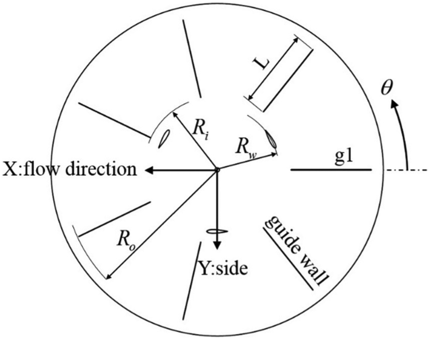
Guide walls of the wind power tower and a wind turbine in the center plane.
The origin of the coordinate on the WPT was selected to be a point where the center line of the shaft of the VAWT crossed the upper plane of the turn table. The X-direction was set to the wind flow direction, and the Y-direction and Z-direction were set to the side direction and vertical direction, respectively. Figure 3 shows the geometric configuration of the WPT, viewed from upstream. The WPT was installed at a height of

Wind power tower and wind turbine, viewing upstream.

Picture of wind power tower and a vertical axis wind turbine.
The shaft of the VAWT was directly connected to a torque sensor, and this torque sensor was serially connected with a generator, as shown in Figure 5. The output power produced in the generator was dissipated on a load bank. This load bank was applied to control the output power of the VAWT using a variable resistance. The output power of the generator was measured using a power-meter. However, this output power did not include losses that were generated by the components of the VAWT, or by the experimental devices linked to the generator. Hence, the output power transferred to the generator was measured using a torque sensor. The data, including temperature and rotational speed, were acquired using a data acquisition system.

Picture of components connected with a vertical axis wind turbine.
By installing the WPT in a wind tunnel, the velocity in the cross-section plane upstream could be slightly varied depending on the measuring location, due to blockage. In this experiment, the inlet velocity (
Model and accuracy of instruments.

Results and analysis
VAWT alone
Before measuring the effectiveness of the WPT, the performance of the VAWT without the WPT was measured. Since the VAWT was manufactured as a small-scale model, the performance of the VAWT could be affected by many factors, including the number of bearings, the efficiency of connecting parts, the manufacturing accuracy of the model, the blade profile, the material of the blade, and so on, even though the same experimental conditions were applied. Therefore, the experimental results were compared with results obtained on the same VAWT model as well as the same connecting parts.
In a small-scale model, unlike an actual scale VAWT, power losses due to the connecting parts have a large effect on the output power obtained from the wind energy. To account for this, the power losses of the VAWT model were measured at various rotating speeds using a motor instead of the generator. During the measurement, wind blew at a speed of 1 m/s, so that the wake generated by the blade would not stay in the rotating region of the blades. The power loss on the generator was also measured in a state of unload, and the devices used to measure it are shown in Figure 6.

Picture of devices used to measure the power loss on a generator.
In the experiments with the VAWT model, the performance curve could be varied by two major parameters, inlet velocity and load on the generator. In a condition of constant inlet velocity, the tip speed ratio (
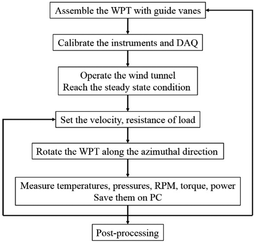
Experimental flow chart.
Figure 8 shows the performance curves obtained by varying the inlet velocity while the load was kept constant. The load was directly related to the resistance of the load bank, and the load increased when the resistance was decreased. The load in Figure 8 is expressed as the resistance ratio (
Variation of power coefficients on a vertical axis wind turbine.
Figure 9 shows the power coefficient curves formed for an equal inlet velocity condition, while the load was changed. The dotted line expresses the performance curve obtained with low inlet velocity. The performance curve for the increased inlet velocity is expressed with the dashed dotted line. In the experiment of VAWT alone, the low power coefficient curves were obtained in a region of low tip speed ratio, as shown in Figure 9. This occurred because the experiment was conducted at a Reynolds number of 4.6 × 10⁴, which was low compared with that of full-scale VAWTs. Other test 26 conducted with a same scaled VAWT showed similar power coefficient curves like these experimental results, although the wind velocity was greatly increased to reach a higher Reynolds number of 1.9 × 10⁵. Even though the results obtained in this experiment showed the lower power coefficient, these can be useful to investigate the optimal design parameters of the WPT through relative comparison when these results are consistent based on the experimental uncertainty.

Variation of power coefficients obtained based on equal inlet velocity.
VAWT with the WPT
The performance of the VAWT installed inside the WPT varied depending on the relative location of the guide wall against the wind flow direction. As a result, it would require a huge number of performance tests to obtain the performance curve of the VAWT since there are many relative locations in a periodic azimuth angle on the WPT. If the performances are compared relatively, however, it is not necessary to measure the performance curves of the VAWT at every relative location. As shown in the performance curves of the VAWT alone, they did not cross each other when results were obtained by varying the load with a constant inlet velocity, or by varying the inlet velocity at a constant load. In order to compare the performance of the VAWT with the WPT, an experiment was conducted with the same conditions of equal load and equal inlet velocity. The power coefficient was obtained for each relative location. Then, these power coefficients were averaged for one periodic azimuth angle. Since this averaged power coefficient (
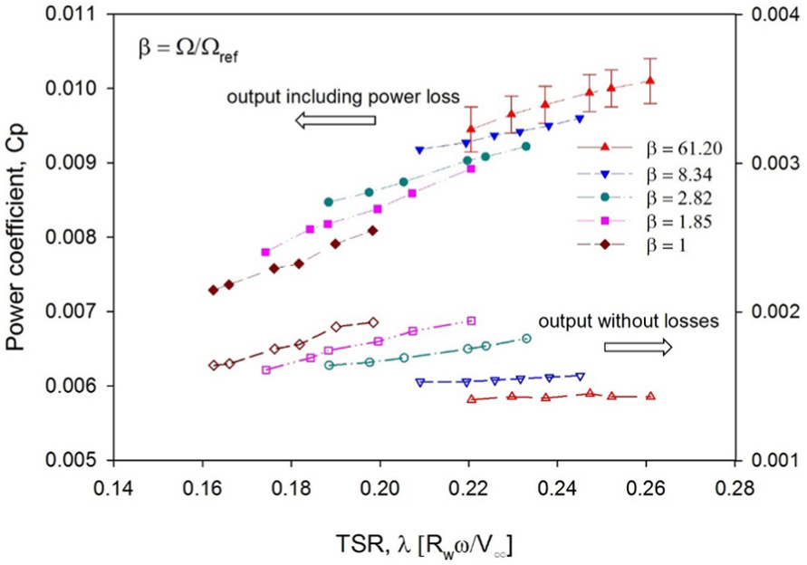
In the experiment with the WPT, the inlet velocity was set to 90% of the maximum velocity in the experiment of the VAWT alone (δ = 90%), and the load was set to the resistance ratio of β = 61. The application of low load was necessary so that the VAWT could be studied under many different operating conditions, due to the variation in design parameters on the WPT. Figure 10 shows the power coefficients obtained with three different guide walls. The axis of abscissa was expressed by the non-dimensional azimuth angle (

Variation of power coefficient for different inner gaps as (a) SGW, (b) MGW, and (c) LGW.
The power coefficient curves showed very similar trends for the equal inner gap, even though three different guide walls were applied, as shown in Figure 10. When the WPT was rotated from
When the inner gap was reduced to
To compare the power coefficients based on the same inner gap, instead of the same guide wall, they were redrawn, as shown in Figure 11. For the case of an inner gap of

Comparison of power coefficients with equal inner gaps as (a) εin = 0.2, (b) εin = 0.3, and (c) εin = 0.4–0.42.
When the inner gap was increased to
In a 2.5-D computational study
24
of full-scale model, the better power coefficient was obtained at
Since the VAWT inside the WPT was affected by the wind flow direction, the effectiveness of the WPT could be obtained by integrating the power coefficient for at least one periodic azimuth angle, so that it could be independent of the wind direction, as in equation (1). Nonetheless, the measurement of the power coefficient was conducted at 13 locations for one periodic azimuth angle. Thus, an averaged power coefficient (

Figure 12 shows the variation in the averaged power coefficient for the different inner gaps. The averaged power coefficient obtained near the inner gap of

Variation of averaged power coefficient with various inner gaps.
Conclusion
In order to investigate the optimal design parameters for a WPT used to augment the performance of a VAWT, an experimental study was conducted in a wind tunnel. Seven guide walls were used for the WPT and three different types of guide walls were applied to test with several design parameters. The inner gap was the major design parameter affecting the performance of the VAWT, and its optimal value was found to be between
Footnotes
Appendix 1
Handling Editor: Jose Ramon Serrano
Declaration of conflicting interests
The author(s) declared no potential conflicts of interest with respect to the research, authorship, and/or publication of this article.
Funding
The author(s) disclosed receipt of the following financial support for the research, authorship, and/or publication of this article: This research was supported by “the renewable energy innovation project” of the Korea Institute of Energy Technology Evaluation and Planning (KETEP) granted financial resource from the Ministry of Trade, Industry & Energy, Republic of Korea. This financial support is gratefully acknowledged.