
Abstract
Compared with a drag-type vertical axis wind turbines, one of the greatest advantages for a lift-type vertical axis wind turbines is its higher power coefficient (Cp). However, the lift-type vertical axis wind turbines is not a self-starting turbine as its starting torque is very low. In order to combine the advantage of both the drag-type and the lift-type vertical axis wind turbines, a lift drag hybrid vertical axis wind turbines was designed in this article and its aerodynamics and starting performance was studied in detail with the aid of computational fluid dynamics simulations. Numerical results indicate that the power coefficient of this lift drag hybrid vertical axis wind turbines declines when the distance between its drag-type blades and the center of rotation of the turbine rotor increases, whereas its starting torque can be significantly improved. Studies also show that unlike the lift-type vertical axis wind turbines, this lift drag hybrid-type vertical axis wind turbines could be able to solve the problem of low start-up torque. However, the installation position of the drag blade is very important. If the drag blade is mounted very close to the spindle, the starting torque of the lift drag hybrid-type vertical axis wind turbines may not be improved at all. In addition, it has been found that the power coefficient of the studied vertical axis wind turbines is not as good as expected and possible reasons have been provided in this article after the pressure distribution along the surfaces of the airfoil-shaped blades of the hybrid turbine was analyzed.
Keywords
Introduction
At present, horizontal axis wind turbine (HAWT) has been widely used. However, the vertical axis wind turbine (VAWT) has many advantages, and people are paying more and more attention to it. The main advantage of VAWT is that it has a single moving part (the rotor) and also no yaw mechanisms are required. Therefore, the configurations of VAWT are usually very simple. 1 Besides, their manufacturing costs are lower, their fabrication is easier, and their installation and maintenance are more convenient than the HAWT. There are two types of VAWTs: those that operate using lift and those that operate using drag. 2 The typical structure of the drag-type VAWT is the S-type (Savonius) wind turbine, which is composed of two or more semi-cylindrical blades rotating around an axis parallel to the blades. The advantages of this kind of wind turbine are the high starting torque and good self-starting capability. But both the rotating speed and the power coefficient of this type of turbine are low. 3 The other main type of VAWT is the Darrieus type which has various forms, including H-type and Φ-type. Although the lift-type VAWT is not self starting, it has higher power coefficient (Cp) and are typically more efficient than other types of VAWTs. 4 Numerous researchers worldwide are attempting to identify effects of the key design parameters of the Darrieus rotor, such as the number of blades, blade solidity, and airfoil type on its energy characteristics by means of experimental and numerical techniques. A series of numerical simulations were conducted by S Li and Y Li 5 to investigate the influence of solidity on a Darrieus-type straight-bladed vertical axis wind turbine (SB-VAWT). They found that the VAWT with larger solidity can achieve higher power coefficients at lower tip speed ratios but too large solidity will decrease the power coefficient. Even for the Darrieus VAWT with same solidity, its power performance can still be highly affected by different combinations of number of blades and chord length. Castelli et al. 6 numerically analyzed the effect of solidity and concluded that, by increasing the number of blades from three to five, the numerically predicted peak of power coefficient lowered with the increase in rotor solidity. Abu-El-Yazied et al. 7 used simulation to compare power performance of a two-, three-, four- and six-bladed SB-VAWT characterized by a NACA0021 airfoil. They found that the two-bladed rotor configuration shows the best power performance and the obtained peak of power coefficient decreased with the increase in rotor solidity. Their findings are consistent with Howell et al.’s 8 and Castelli’s even though the airfoil shape employed in their studies were different. The NACA 4-digit series airfoil is commonly used in VAWT studies, most notably NACA0012, NACA0015, 9 and NACA0018. 10 However, several studies over recent years have suggested that NACA 4-digit series airfoil may not be an optimal airfoil shape for use in the SB-VAWT. Mohamed 11 studied the characteristics of a SB-VAWT with 20 different symmetric and non-symmetric airfoils, respectively, by two-dimensional (2D) computational fluid dynamics (CFD), and his numerical results showed that compared to a conventional (NACA 4-series) airfoil, the S-1046 airfoil appears to be more promising airfoil for VAWTs. Sabaeifard et al. 12 investigated DUW airfoil effects on H-Darrieus wind turbine efficiency comparing with a NACA 0018 airfoil. With the aid of scale model experiments, Ragni and Ferreira 13 also confirmed that the DU12W262 airfoil can offer superior performance than the NACA 4 series airfoils. More recently, other researchers have been looking into some of the different approaches to improve Darrieus wind turbine performance. Kim and Gharib 14 proposed an approach to increase the power output of the Darrieus VAWT using an upstream flat deflector. N Morgulis and A Seifert 15 tried to enhance dynamic performance of a vertical axis Darrieus-type wind turbine using a variety of passive flow control and active flow control techniques. They found that using active flow control (boundary layer suction or pulsed suction), the net efficiency of the turbine can be greatly increased with lower power consumption. For detailed review of various configurations and design techniques of the VAWT, readers are referred to Barot et al. 16 and Bhutta et al. 17
In order to improve the starting torque of the lift-type VAWT, this article studied a lift drag hybrid-type VAWT, which has combined the benefits of the Savonius-type blade (semi-cylindrical shape) and the Darrieus-type blade (airfoil shape) and took advantage of both the drag and lift forces generated by the wind. The 2D cross section of the studied lift drag hybrid VAWT is shown in Figure 1. When there are lift-type blades alone, it then becomes a typical lift-type VAWT. Four different lift drag hybrid VAWTs were numerically analyzed in this work and they were named, respectively, as hybrid turbine 1, hybrid turbine 2, hybrid turbine 3, and hybrid turbine 4. The only difference among those simulated hybrid turbines was the distance between their drag-type blades and rotation center d: the drag-type blades of hybrid turbine 1 were installed in the rotational center, while the drag-type blades of hybrid turbine 2, hybrid turbine 3, and hybrid turbine 4 were, respectively, installed at 50, 100, and 150 mm away from the rotational center. The three inner drag-type blades, each shaped like a half-cylinder with radius of 250 mm as well as three outer lift-type blades, shaped like aircraft wings, rotated together about a central axis. The geometry of the lift-type blades was NACA0018 airfoil with the chord length of 500 mm and the simulated turbine was 3 m in diameter. Thus, the solidity of the lift-type VAWT (σ = Nc/D), which is a function of the number of blades N, the chord length of the blades c, and the diameter of the rotor D, was 0.5. In this study, CFD commercial software Fluent was used to conduct numerical simulations of steady and unsteady flow around this hybrid-type VAWT rotor in order to study its aerodynamics and starting performance (Table 1).
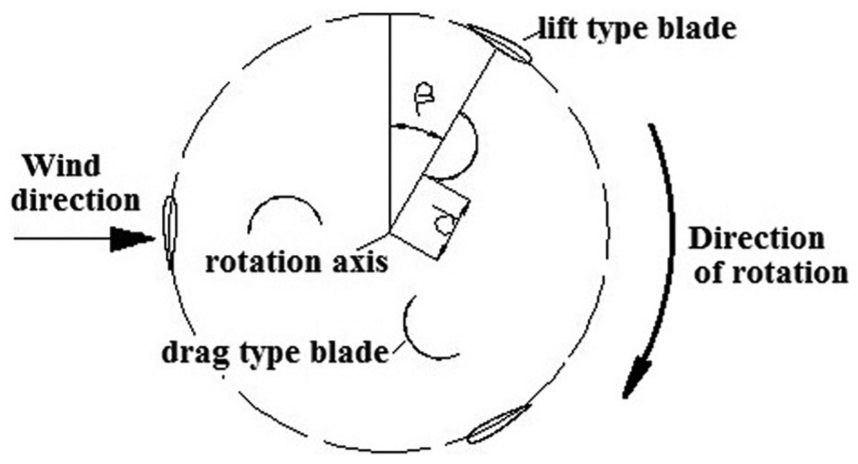
Top view of the physical model.
Simulated VAWTs named based on the distance between their drag-type blades and the center of rotation axis (d).

VAWT: vertical axis wind turbine.
It was originally assumed that that this lift drag hybrid VAWT would not only have the higher starting torque than that of the lift-type VAWT but also have a high power coefficient Cp since the lift-type blades and drag-type blades work together to produce power.18–20 However, in this research, it was found that this lift drag hybrid wind turbine did have a higher starting torque than that of the conventional lift-type VAWT, but its Cp was unexpectedly low.
Establishment of numerical model
Governing equations
Numerical solution was based on the finite volume method. The governing equations for incompressible fluid flow include continuity (conservation of mass) and the Navier–Stokes equations (conservation of momentum), 21 which are expressed, respectively, as follows


where j = 1, 2 and i = 1, 2.
Selection of turbulence model
The model of equation (2) reflects the fact that the flow around the rotating blade was turbulent, and closure of the Reynolds-averaged Navier–Stokes (RANS) equations were achieved using the shear stress transport model.
Simulations were performed with different turbulence models, such as the standard k–epsilon turbulence model, the standard k–ϖ turbulence model and Spalart–Allmaras (S-A) model, to assess the influence of different turbulence models on obtained computational results. It has been found that the power and torque coefficients obtained using different turbulence models were all in good agreement with the published experimental results. Consequently, the S-A model was chosen due to the satisfactory results obtained over a wide range of flows and due to its numerical properties.
The S-A used is the implementation in the CFD package Fluent Inc. 22 of the model proposed by Spalart and Allmaras. 23 It is a relatively simple one-equation model that solves a modeled transport equation for the kinematic eddy (turbulent) viscosity. In the turbulence model of S-A, the transport equation can be written as follows

where v is the molecular viscosity calculated by Sutherland’s law. The four terms on the right-hand-side are production, diffusion, dissipation, and transition, respectively. In addition, the definitions of the individual components of the production term are as below


In the above equations, S is the magnitude of the vorticity, d is the distance to the closet wall, dt is the distance from the point in the flow field to the trip on the wall, ωt is the wall vorticity at the trip, ΔU is the difference between velocity at the field point and that at the tip, and gt = min(0.1, ΔU/ωtΔxt), where Δxt is the grid spacing along the wall at the trip.
The empirical constants of the S-A model are as follows: Cb1 = 0.1355, σ = 2/3, Cb2 = 0.622, κ = 0.4187, Cw1 = 3.239, Cw2 = 0.3, Cw3 = 2.0, Cv1 = 7.1, Ct1 = 1, Ct2 = 2, Ct3 = 1.2, and Ct4 = 0.5.
Computational domain
The physical domain used in this study is shown in Figure 2. The wind turbine was placed in the middle of the computational domain at a distance of 20 rotor diameters (20D) from the upstream boundary. Besides, the downstream exit boundary was located at 40D from the center of the rotor, in order to minimize the influence of boundary conditions. The computational domain was divided into a moving zone rotating with the turbine blades and a stationary zone.
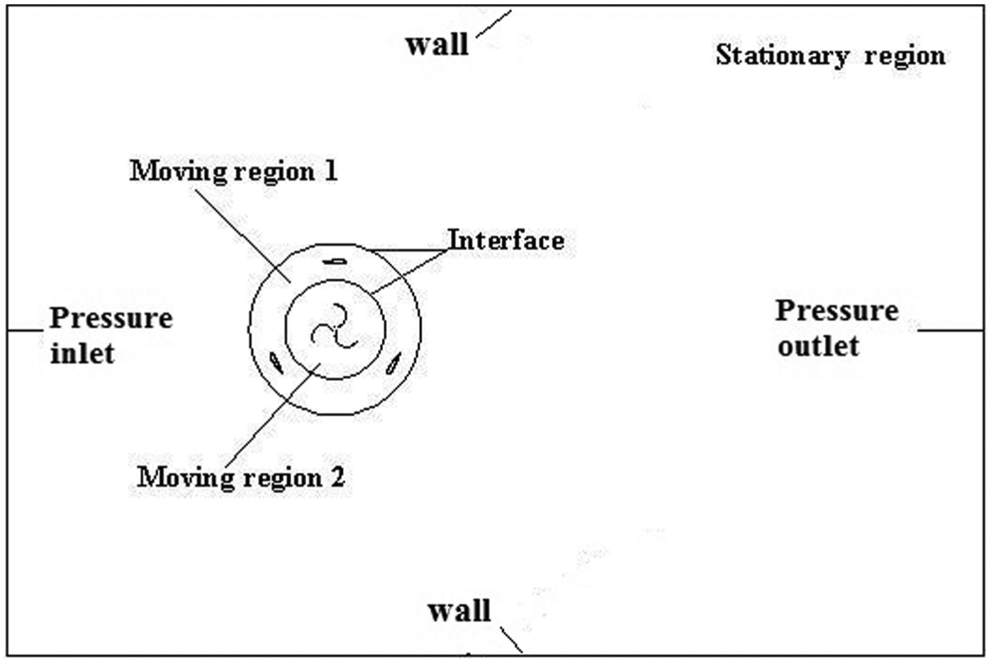
Schematic of the computational domain.
Computational mesh generation
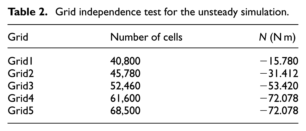
The computational domain was meshed using unstructured grid which consists of triangular element in order to maximize the number of cells in the area of interest while minimizing cells in the far field. The grid was locally refined in an attempt to resolve the boundary layer near the surface of the rotor blade and reduce the numerical errors. As the quality of the computational gird is essential to the accurate and stable numerical analysis, a grid independence test was performed in this study to identify the optimal number of cells of the computational domain mesh. The VAWT model of hybrid turbine 1 was used in all the grid independence tests.
Table 2 shows the results of grid independence test study performed with CFD calculations. Here, N represents the dynamic torque of the simulated hybrid turbine 1. This table shows that the number of cells obtained with the Grid4 and Grid5 is satisfactory in predicting coherent simulation results.
Grid independence test for the unsteady simulation.
The computational set-up
Assuming the wind blows from left to right, the boundary conditions imposed on the boundaries of the computational domain were as follows:
Inlet boundary: the inlet total pressure. The given pressure was 49.6125 Pa, which was equivalent to the wind speed of 9 m/s;
Outlet boundary: a static (gauge) pressure at the outlet. The given static pressure was 0 Pa (relative pressure);
Wall boundary: the upper and lower boundary conditions were wall, as the simulated wind turbine was assumed to rotate in a wind tunnel. No slip rotating wall boundary conditions were used along the blade surfaces;
Slip plane: there was the sliding mesh interface between the rotating and the stationary grids, thus ensuring the continuity in the flow field.
Numerical simulation of unsteady flow and aerodynamic performance of the lift drag hybrid VAWT
In this article, CFD software was used for numerical simulation of the aerodynamic performance for wind turbines’ blade wheel at rated wind speed, which was set at 9 m/s. The second-order upwind discretization and the pressure-based implicit algorithm were adopted for solving the flow field. For this study, computations were conducted with 250 physical time steps during a rotation period of the rotor and the time step size was set as T/250. In all the simulations, 20 iterations per time step were used. It has been found that after the result has converged, the torque coefficient of the rotor showed a clearly time period trend and the final torque coefficient was then calculated by averaging the results during one revolution of the rotor.
N represents the dynamic torque and is calculated using the following equation

where ρ is the air density, v is the standard unit velocity, A is the standard unit area, L is the standard unit length, and Cm is torque coefficient.
P represents the power output of the simulated turbine and is calculated as follows

where N is the torque and ω is the rotor’s angular velocity.
Cp is the power coefficient defining the aerodynamic efficiency of the wind turbine rotor and its equation is given below
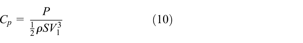
where P is the actual power extracted from the wind, S is the swept area of the turbine rotor, and V1 is the wind speed.
The tip speed ratio λ for wind turbines is the ratio between the rotational speed of the tip of the turbine blade and the actual velocity of the wind and is calculated as follows
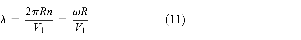
where n is the rotational speeds of the rotor and R is the radius of the rotor.
Starting torque is the driving torque of the machine which overcomes mechanical friction and drag at zero rotational speed. 21
Numerical model validation
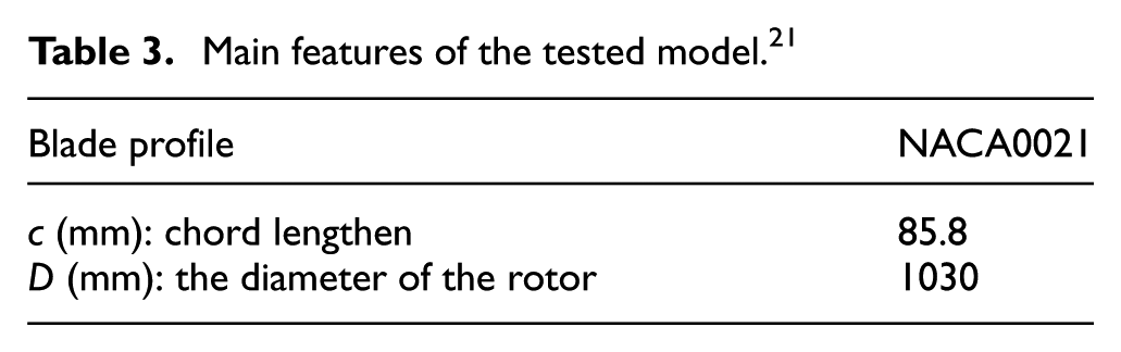
A validation study has been conducted, in which a conventional Darrieus turbine studied in Castelli et al. 21 was also simulated and results of this validation have been used to assist in determining the appropriate turbulence models, boundary conditions, mesh characteristics, and other CFD modeling techniques used in this work. The main geometric features of the model tested in Castelli et al. 21 is given in Table 3, and a comparison between the published results achieved from Castelli et al. 21 and the results achieved in this study is illustrated in Figure 3.
Main features of the tested model. 21
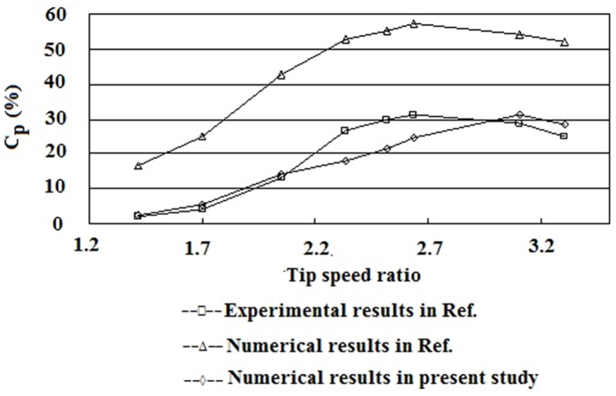
From Figure 3, it can be seen that the numerical results obtained in this work are much close to the results from the model tests, proving the accuracy of the current numerical method. However, the predicted optimum value of tip speed ratio λ that gives a maximum power coefficient Cp is larger than that measured in Castelli et al. 21
According to studies conducted by Gosselin et al. 24 and Li and Calisal, 25 the power performance of a H-Darrieus VAWT has been heavily influenced by its blade aspect ratio AR (the ratio of the blade length to the chord length). When AR > 72, the power produced by an actual turbine could be 95% of the numerically predicted 2D efficiency because of the finite aspect ratio effects. The less the AR of a real turbine blade is, the lower will be its power coefficient compared to the values predicted from a 2D CFD simulation.
Gosselin’s results suggested that when AR = 15, the three-dimensional (3D)/2D efficiencies ratio could be 69.0%. 22 For the Darrieus VAWT reported in Castelli et al. 21 whose experimental data were used for validating numerical results, its blade aspect ratio is about 17 (blade height 1456.4 mm/chord length 85.5 mm). Furthermore, the experimental results also did not correct blockage effects. Therefore, the difference between results of our 2D numerical simulation and experimental results reported in Castelli et al. 21 could be less than 30% considering the above two effects. In general, the numerical scheme proposed herein is an adequate tool for obtaining the aerodynamics and performance of VAWT.
Subsequently, the established numerical model was used to simulate the flow field around the lift drag hybrid wind turbines with different geometric configurations.
Results and discussion
Comparison of starting torque
Under a certain wind speed, the torque generated by wind when the rotor is stationary directly determines turbine’s starting performance. In order to study the starting characteristics of the lift drag hybrid wind turbine, a series of simulations on the static torque performance of this type of turbine at different static azimuth angles
Four lift drag hybrid wind turbines which were numbered hybrid turbine 1, hybrid turbine 2, hybrid turbine 3, and hybrid turbine 4 were simulated. For the purpose of comparison, a conventional H-type Darrieus (lift-based) turbine was also numerically analyzed, which has the same rotor diameter, number of blades, and blade airfoil section as the simulated hybrid turbine. Due to symmetry, the azimuth angles
Static torque of all the wind turbines at different positions.


Starting torque of simulated wind turbines.
From Figure 4, it can be found that the minimum torque of a conventional H-type Darrieus VAWT is 1.640 N m when
For the hybrid turbine 4, its drag-type blade was placed farthest from its rotation center, but its starting torque has been significantly improved and the turbine can be self-starting at any azimuth angle. This result suggests that the lift drag hybrid turbine has the advantage of high starting torque, and the position of its drag-type blade seems to be very important. If the drag-type blade is placed very close to the spindle of the turbine, there will be no improvement in the starting performance of this hybrid-type turbine. With the distance between the drag-type blade and the center of the turbine rotor increasing, the starting torque of the hybrid turbine is also gradually increased.
Comparison of power coefficient (Cp)
In order to compare the power coefficient Cp between the conventional Darrieus VAWT and the hybrid VAWT, CFD simulations of the wind turbine rotating motion have been conducted at a certain wind speed.
Aerodynamic characteristics of the studied wind turbines rotating at a certain speed have been achieved and the rotation speeds examined were 70, 83, 97, 111, 125, and 138 r/min, respectively, as shown in Table 5.
Different rotation speeds used in the numerical model.

Figure 5 is a comparison of power coefficient among all the simulated turbines. From Figure 5, it can be seen that the optimum tip speed ratios of four hybrid turbines that maximize the power coefficient Cp are all around 1.75. However, compared to the conventional Darrieus turbine, the power coefficients of all the hybrid turbines are relatively low. Among the simulated hybrid turbines, the power coefficient Cp of hybrid turbine 1 is the highest, while hybrid turbine 4 shows the lowest Cp. Therefore, the distance from the drag-type blade to the center of the wind turbine’s rotor d apparently influences the power output of the hybrid turbines. When the drag-type blade is placed far away from the axis of rotation, the Cp of the hybrid turbine can be considerably reduced.

Comparison of the variation of the predicted power coefficient with tip speed ratio for all the simulated turbines.
The calculated averaged dynamic torque of the conventional Darrieus VAWT and the dynamic torques produced, respectively, by the lift-type blades and the drag-type blades of hybrid turbine 4 are compared in Figure 6.

Comparison of dynamic torque of the Darrieus-type turbine with those generated by the lift-type and drag-type blades of hybrid turbine 4.
As can be seen in Figure 6, the dynamic torque of the Darrieus-type VAWT is slightly higher than that generated by the lift-type blade of the hybrid turbine 4. Moreover, the torque produced by the drag-type blade of hybrid turbine 4 is fairly small which indicates that the drag-type blades almost do not make any positive contributions to the power output of hybrid turbine 4. Thus, it would be wrong to assume that both the lift-type and drag-type blades of the hybrid VAWT can do positive work during their operation.
In addition, possible reasons for the low Cp of hybrid VAWT have also been investigated in this article. When the turbine rotor was rotated to different azimuth (β) positions, static pressure distributions on the blade airfoil surface were analyzed and provided in Figure 7(a)–(l), in which two curves, respectively, represent the airfoil-shaped blades of the Darrieus turbine and the hybrid turbine 4.
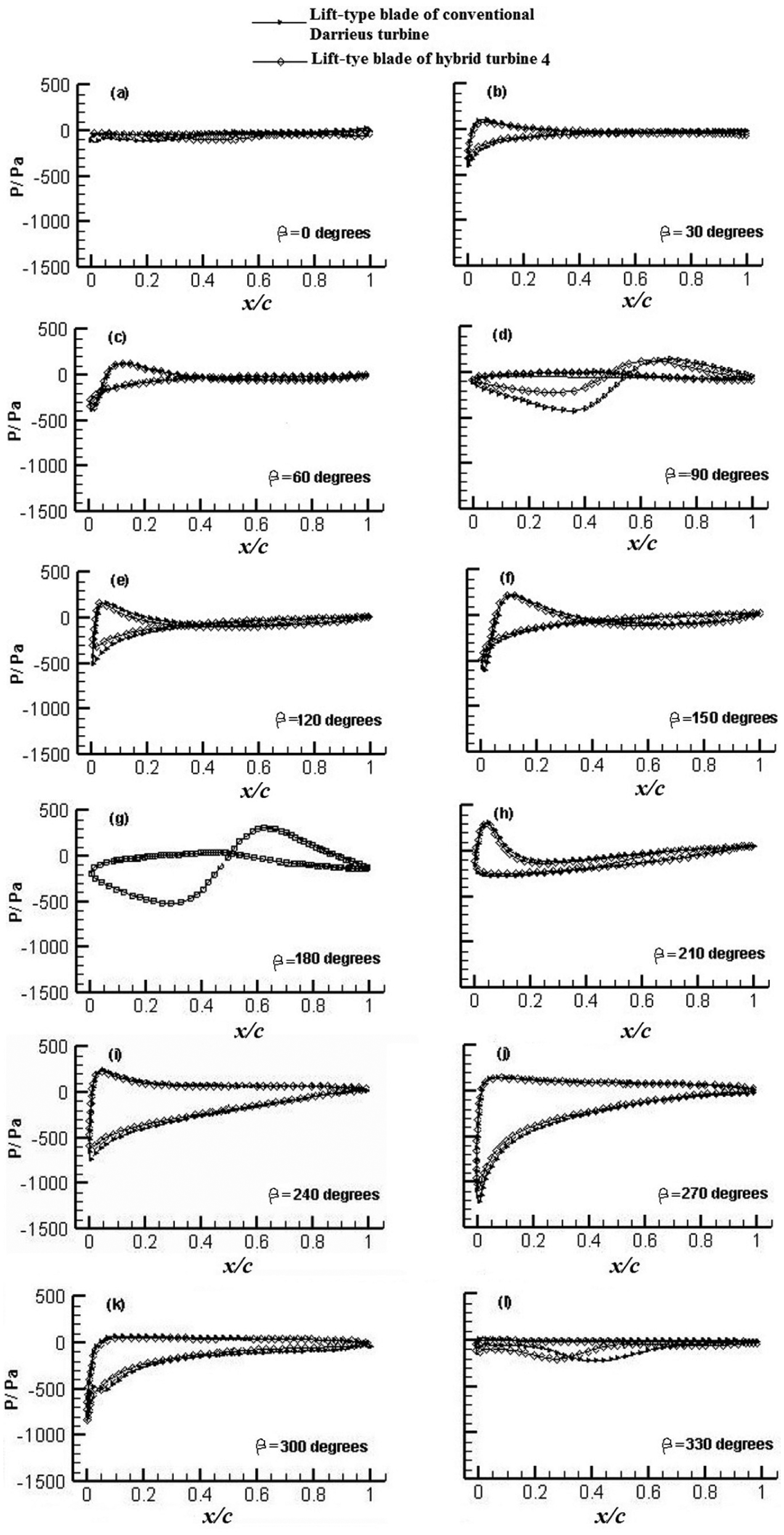
Static pressure distribution on the surface of the airfoil-shaped blade of the rotor at different azimuth positions: (a) 0 degree, (b) 30 degree, (c) 60 degree, (d) 90 degree, (e) 120 degree, (f) 150 degree, (g) 180 degree, (h) 210 degree, (i) 240 degree, (j) 270 degree, (k) 300 degree, and (l) 330 degree.
Figure 7(a) shows the static pressure distribution on the airfoil surface when β is 0° and the blade is parallel to the wind. In this position, the pressure difference between pressure and suction surface of the blade is relatively small and as a result, neither the blade of the Darrieus-type VAWT nor the lift-type blade of the hybrid turbine 4 captures the energy of the wind.
Figure 7(b) shows the blade surface static pressure distribution when β is 30°. It has been found that a large pressure difference between pressure and suction surface appears in the 40% front part of the blade, which means that only a region of 40% of the chord length of the blade body can generate power and the rest 60% of the blade almost does not work. From Figure 7(b), it has also been noted that the pressure distribution on the blade of the Darrieus VAWT is nearly identical to that of the hybrid VAWT.
Figure 7(c) illustrates the pressure distribution on the airfoil-shaped blade surface when β is 60°. This result confirms that the leading edge of the blade does negative work. On 5%–35% chord of the lift-type blade, pressures on pressure surface are higher than that on suction surface. But on the left 65% blade, the pressure difference between pressure and suction surface is very small. It can also be found that there is little difference between the pressure on the blade of Darrieus VAWT and that on the airfoil-shaped blade of the hybrid VAWT.
Figure 7(d) shows the pressure distribution on the airfoil-shaped blade surface when β is 90°. The pressures on the pressure side of the blade are found to be higher than those on suction surface on the surface of the front 60% blade; otherwise, on the left 40% blade, the pressures on pressure surfaces are lower. It can also be found that the difference of pressure between pressure surface and suction surface of the lift-type VAWT is significantly larger than that of the hybrid turbine.
Figure 7(e) shows the pressure distribution on the airfoil surface when β is 120°. It suggests that the pressures on the pressure surface are higher than that on suction surface on the surface of the front 35% chord of the lift-type blade. Difference of pressure on the lift-type blade between pressure surface and suction surface of the Darrieus VAWT is a little larger than that of the hybrid turbine. It has also be found that the pressures on the pressure surface are a little lower than those on suction surface on the rest 65% blade surface.
Figure 7(f) shows that the pressure distribution on the airfoil surface when β is 150°, which is similar to the results obtained in Figure 7(c), but the pressure difference between pressure and suction surface becomes a little larger.
Figure 7(g) shows that the pressure distribution on the airfoil surface when β is 180°. It can be seen that on front half of the blade, the pressures on the pressure surface are higher than that on suction surface, while the pressures on the pressure surfaces are lower than those on suction surface on the rest half of the blade. There is almost no difference between the pressure on the blade of Darrieus-type VAWT and the pressure on the lift-type blade of hybrid VAWT.
Figure 7(h) shows that the pressure distribution on the airfoil surface when β is 210°. It shows that the pressures on the pressure surface are always higher than those on the suction surface. The pressure difference between the pressure and suction surface at the leading edge is the largest. From the front 20% chord to trailing edge of the blade, pressure difference between pressure and suction surface is relatively small. It can be seen that the pressure distribution on the blade of the lift-type VAWT is similar to that on the lift-type blade of the hybrid VAWT.
Figure 7(i) shows that the pressure distribution on the airfoil surface when β is 240°. It shows that the pressures on pressure surface are always higher than that on suction surface. The pressure difference on the surface near the leading edge of blade is larger than that on the surface of other positions. It can also be found that the difference of pressure between pressure surface and suction surface of the Darrieus VAWT is larger than that of the hybrid turbine.
Figure 7(j) and (k), respectively, shows the pressure distribution on the airfoil surface when β are 270° and 300°, which are similar to the results displayed in Figure 7(i). The pressure difference between pressure and suction surface of Figure 7(j) is the largest among all the results demonstrated in Figure 7.
Figure 7(l) shows that the pressure distribution on the airfoil surface when β is 330°. It can be seen that pressures on the pressure surface are higher than that on the suction surface of the front 70% chord of the lift blade, although the pressure difference between pressure and suction surface is small. For the Darrieus VAWT, the largest pressure difference between pressure and suction surface appears at the front 30% of the blade; however, for the hybrid VAWT, it appears at the front 40% of the blade.
In general, the pressure difference on the lift-type blade of hybrid turbine 4 is lower than that on the blade of the conventional Darrieus turbine at most of blade operating positions, which is one possible reason resulting in poor power coefficient Cp of the hybrid VAWT. That is, the Darrieus-type VAWT has much stronger capability in extracting energy from the wind compared with this lift drag hybrid-type VAWT. In addition, the velocity field and the system wake behavior could also be responsible for the inferior performance of the hybrid VAWT. To confirm this assumption, large eddy simulation (LES) or detached-eddy simulation (DES) models of turbulence that allow accurate investigations of the complex unsteady flows over wind turbine rotor blades including phenomena, such as dynamic stall, seem necessary.
Conclusion
This study indicates that the lift drag hybrid VAWT whose lift-type and drag-type blades are appropriately combined can achieve a higher starting torque than that of a conventional Darrieus-type VAWT. In addition, the starting torque of this hybrid VAWT is increased when its drag-type blade is moved away from the center of rotation of the turbine rotor. However, the power coefficient of the hybrid-type turbine is generally lower than that of the Darrieus-type VAWT and can be further reduced with the increase in the distance between its drag-type blade and the center of rotation.
Further work
Based on the above analysis, a new hybrid-type VAWT can be designed whose drag-type blades can be automatically adjusted. When the turbine rotor at rest begins to rotate, its drag-type blades are originally located 150 mm from the axis of the rotor’s rotation, creating very high starting torque and thus this turbine can be self starting at low wind speeds. Once the turbine rotates, its drag-type blades can be moved from its original position to a position as close as possible to the axis of the rotor’s rotation in order to achieve high power coefficients. A small-scale model of this envisaged hybrid wind turbine will be constructed in the future and its aerodynamic characteristics will be studied through wind tunnel testing.
Footnotes
Academic Editor: Sergio Nardini
Declaration of conflicting interests
The author(s) declared no potential conflicts of interest with respect to the research, authorship, and/or publication of this article.
Funding
The author(s) disclosed receipt of the following financial support for the research, authorship, and/or publication of this article: This work is supported by the National Natural Science Foundation of China (no. 51536006 and 51376096) and USST Key Laboratory of Flow Control and Simulation (D15013).