
Abstract
Steam-assisted gravity drainage has been proven to be an effective oil recovery method, and the technology of magnetic location is the key to steam-assisted gravity drainage. In view of the rapid development of this technology in China, a new magnetic location system with intellectual property rights was developed in this article, including mechanical parts and circuit section of detection system. Specific structure, operating principle, and technical parameters of magnetic source generator and detection system were designed and analyzed. The ground test results show that the source generator is powered by an alternating current of 4–7 A, the detection system can probe the magnetic field signal 25 m away from the magnetic source generator, and the measurement error is less than 3% by comparison of measured with actual spacing distance. The steam-assisted gravity drainage dual-horizontal well group in Zhong 37 Well block in Fengcheng Oilfield is chosen for further experiment with the developed magnetic location technology. The results of field experiment show the trajectories of Wells I (injection well) and P (production well) are basically matched in the horizontal projection, and the measurement error is within the allowable range. The magnetic location system developed in this article can meet the operational requirement in steam-assisted gravity drainage dual-horizontal wells.
Keywords
Introduction
The heavy oil makes up a large proportion of global oil and gas resources, and it is an important part of oil hydrocarbons. The statistics shows that there is about 1000 × 108 tons of heavy oil, ultra-heavy oil, and natural bitumen reserve in the world. China has a wide distribution of heavy oil and bitumen resources, with over 70 heavy oil fields in 12 basins and over 300 × 108 tons of resources.1–3 When a large amount of conventional oil resource is produced, the oil production is pointed to the heavy oil and ultra-heavy oil which are not easily accessible. The optimum method of producing the heavy oil and ultra- heavy oil resources is the thermal oil recovery. However, some problems have arisen in the development of heavy oil with steam huff and puff. In order to further enhance recovery of oilfield and stabilize the oil production, it is urgent to change the way of producing the heavy oil. Practice has proven that steam-assisted gravity drainage (SAGD) increases the recovery by 60%, 30% higher than conventional cyclic steam stimulation. SAGD has been proven to be an effective heavy oil thermal recovery technology.4–6
Figure 1 shows the method of implementing SAGD: a couple of horizontal wells with parallel horizontal sections are drilled at the bottom of the reservoir, the steam is injected into the upper horizontal well, the injected steam moves upward to form a steam chamber and continuously propagates upward and laterally to exchange the heat with oil, and the heated oil and the steam condensate are drained by the gravity to the lower production horizontal well and produced by artificial lift. Drilling SAGD wells needs to accurately control both horizontal sections, which are not only fixed at a spatial distance but also wholly extended in the reservoir sandstone. This requires precise measurement of borehole trajectory and accurate calculation of positions between layers, and the technology of magnetic location is the key to SAGD.

A couple of horizontal wells with parallel horizontal sections are drilled at the bottom of reservoir. Steam injection is in upper hole and oil production is in lower hole.
The magnetic location is referred to a steering technology of determining the distance and orientation of a drilling well relative to a reference well according to the measured magnetic signal. In magnetic location, an artificial magnetic field source is placed in the reference well, and the geometric distribution, frequency, and strength of magnetic field from this source are artificially controlled.
The magnetic location has been widely applied in drilling, such as guiding direction of relief well, parallel operation of dual-horizontal wells in SAGD, and intersection of horizontal well and vertical well. There are several steering technologies such as MGT (magnetic guidance technology), RMRS (rotary magnetic ranging system), SW (single wire guidance), MAGTRaC (magnetic tracking), and PWT (parallel wells technology). Among these technologies, MGT is most widely applied in SAGD. So far, 90% of double horizontal wells have used MGT tools. The MGT has been introduced and applied in the development of coalbed methane in China since 2008, and our researchers have actively carried out the research of MGT and achieved some results.7–11
A new magnetic location system with intellectual property rights was developed in this article, including mechanical parts and circuit section of detection system. Specific structure, operating principle, and technical parameters of magnetic source generator and detection system were designed and analyzed. Tests have been conducted to verify that the magnetic location system developed in this article can satisfy the operational requirement of dual-horizontal wells in SAGD. The research results of this article are of great significance to promote the rapid application of magnetic guidance technology in China.
MGT
Development of technology
In June 1993, Amoco Canada used MGT to drill the world’s first pair of SAGD dual-horizontal wells on the surface of Wolf Lake Oilfield in northern Alberta. After that, the reports showed that more than 150 pairs of SAGD dual-horizontal wells were successively drilled in Alberta, Saskatchewan, Wyoming, California, and Venezuela. At present, the magnetic guide technology is increasingly used to drill the dual-horizontal wells in the heavy oilfield worldwide.12–14
Analysis of error
For SAGD oil production, the spacing between horizontal sections of two parallel horizontal wells is controlled strictly. If these horizontal wells of steam injector and oil producer get too close, the short-circuiting effect of steam is formed between them. If they are too far apart, asphaltene is not fully heated by the steam, which does not result in effective SAGD. For a common drilling program of SAGD, the spacing between horizontal sections of dual-horizontal wells is controlled between 4 and 10 m, and the conventional borehole measurement technology could not meet the requirement of accuracy. The measurement errors between conventional measuring instruments and MGT in Table 1 indicate the special demand of magnetic location in SAGD dual-horizontal wells.15–17
Measurement errors between conventional measuring instruments and MGT. 12

MWD: measurement-while-drilling; EMS: electronic multi-shot system; MGT: magnetic guidance technology.
The system errors of MGT include radial error and arc length error, as shown in Figure 2. The radial error is the actual error of spacing between two horizontal wells, and it always has low value. The arc length error or angle error of drilling well relative to the reference well is less significant in the measurement of positions. With the spacing between two wells less than 10 m, the absolute error of the measuring distance is less than 2 cm, and the arc length error is less than 20 cm.
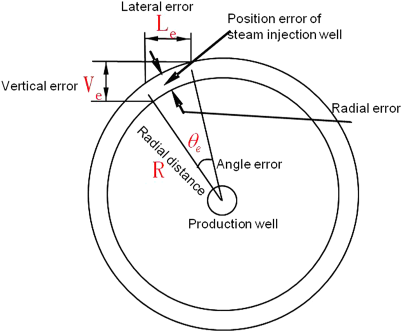
Measurement errors of MGT include radial error and arc length error. The radial error always has low value. The arc length error or angle error is less significant in the measurement of positions.
The magnetic field strength is inversely proportional to the square of measured distance R, which limits the effective measurement distance of MGT. Increasing the magnetic field strength of source generator improves the measurement distance of MGT.
Development of magnetic location system
Design of magnetic source generator
As the magnetic location technology plays an important role and shows great prospect in SAGD drilling, the research of this technology was conducted. The magnetic source generator is vital to magnetic location technology. The developed magnetic source generator (patented, shown in Figure 3) includes cable leader, insulated sub, upper sub, current-conducting rod, insulation sleeve, spring, spring pressing sleeve, fixing sleeve, short lining, current-conducting tube jacket, current-conducting tube, screw rod assembly, contact pin sub, magnetic core, protection jacket, enameled wire, rubber plug seat, rubber plug, guidance unit, and so on.

The structure of the magnetic source generator and its designed parameters: working outer diameter of 50 mm, total length of 2.85 m, maximum working pressure of 50 MPa, working peak temperature of 125°C, diameter of enameled wire of 2.5 mm, and current intensity of 4–7 A.
During the drilling operation of dual-horizontal wells, the tube is run into the lower part of the completed wellbore, the cable is connected with the cable leader, the magnetic source generator is run down into the tube, and the drilling fluid is pumped into the tube to hydraulically pressurize rubber plug to move the tool along the lower wellbore to the designated position. The alternating current power is supplied by the surface power unit to the magnetic source generator, and a magnetic field is generated. The alternating magnetic field signal is probed by the magnetic field detection system in the upper borehole. The magnetic signal is analyzed and processed, and imported into the corresponding magnetic location computation system, and the position of the measured point relative to the magnetic source generator is computed for adjusting the drilling bit position and borehole trajectory in upper drilling borehole. The designed parameters of magnetic source generator include working outer diameter of 50 mm, total length of 2.85 m, maximum working pressure of 50 MPa, working peak temperature of 125°C, diameter of enameled wire of 2.5 mm, and current intensity of 4–7 A.
Mechanical part design of detection system
The magnetic location detection system is placed in the horizontal section of the drilling well, and as the borehole length increases, the system moves forward and receives the magnetic field signal from the magnetic source generator. The signal is analyzed and processed, and the spacing between the detection system and the magnetic field generator and their relative direction are calculated according to the magnetic location model. The mechanical part of the detection system (patented, shown in Figure 4) includes fishing head, centralizer assembly, adjusting sleeve, electronic cabin assembly, outer barrel, measurement-while-drilling (MWD) detection tube, buffer body, directional sub, end connector B, semi-baffle ring, contact pin seat B, battery cartridge sub, centralizer spring, and so on. The designed parameters of the detection system include working outer diameter of 48 mm, total length of 3.5 m, maximum working pressure of 50 MPa, working peak temperature of 125°C, maximum measurement distance of 25 m, and measurement error ≤4%.

The mechanical structure of detection system and its designed parameters: working outer diameter of 48 mm, total length of 3.5 m, maximum working pressure of 50 MPa, working peak temperature of 125°C, maximum measurement distance of 25 m, and measurement error ≤4%.
The lower part of the detection system is connected with the battery cartridge and the mud pulser and inserted in the non-magnetic drill string before tripping into the borehole. When the horizontal section of the upper borehole is drilled, the magnetic field source is tripped into the horizontal section of lower borehole, and powered in a wired method, creating a magnetic signal. The magnetic field and accelerated velocity are measured with the detection system in the upper borehole, and the spacing between the detection system and the magnetic field source and their relative direction are calculated with the magnetic location software. The measurement is operated per footage of one joint in the upper borehole to determine the spacing between detection system and magnetic field source and their direction, based on which the drilling continues by adjusting the tool face angle according to the drilling design. Meanwhile, the magnetic source generator in the lower borehole is moved forward about 10 m. Thus, measurement is repeated to control the borehole trajectory until the horizontal section of upper horizontal well is finished.
Operating principle of circuit section
The operating principle of electronic processing systems is shown in Figure 5. The power management module is responsible for charging, sampling, and radiating circuits. The signal collection boards include No. 1 and No. 2 boards. The former is responsible for collecting the data exported from magnetic field and acceleration sensor, and the latter is responsible for collecting the data exported from MAGWELL magnetic field sensor. The collected data are coded by the collection boards according to a specific format and transmitted to the signal radiating board, where the data are transmitted to ground by controlling the impulse generator.

The electronic processing system includes power management module, signal generation board, signal acquisition board, magnetic field sensor and acceleration sensor, MAGWELL magnetic field sensor, pulse generator, decode box, and so on.
Principal technical parameters of circuit board
Size: 20 mm × 600 mm (width × length); working temperature: 125°C; vibration strength: 20 g; sampling precision and frequency: 12 bits and 6 kHz (No. 1 sampling board) and 24 bits and 112 kHz (No. 2 sampling board).
Magnetic localization model
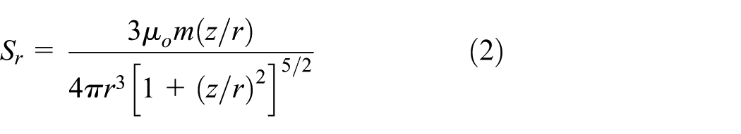
The physical model of magnetic localization is shown in Figure 6. The magnetic field component of magnetic source generator can be expressed as18,19

where

Physical model of magnetic localization. r is the lateral distance between the two wells, and z is the axial distance between the magnetic source generator and the measuring point.
Through a series of deductions, the lateral distance r was found between magnetic source generator and detection system

Ground test
Goal and plan of test
Under normal pressure and temperature, the magnetic source generator and the detection system are placed in a circumstance with little magnetic field interference. A ground test space around 25 m × 25 m is chosen, and the test grids are drawn on the ground, and the spacing between grids is determined as precise as possible (Figure 7). During the test, the magnetic field detection system is fixed at the boundary of test space, and the magnetic source generator is moved in the front and back of and in the left and right of the magnetic field detection system (the magnetic source generator is basically parallel with the magnetic field detection system). The alternating current between 4 and 7 A is supplied to the generator to determine whether the detection system can probe the signal from the magnetic source generator when the source is 25 m away from the detection system. Meanwhile, the measurement spacing between the generator and the detection system (the distance calculated by the magnetic location software) and the actual spacing are compared to analyze the measurement error.

A ground test space around 25 m ×25 m is chosen and the test grids are drawn on the ground. The alternating current between 4 and 7 A is supplied to the generator, which produces the magnetic signal probed by the detection system.
Result of test
According to the results of test on the ground, the detection system can probe the magnetic field signal from the magnetic source generator 25 m away, and the measurement error is less than 3%, as shown in Figures 8 and 9
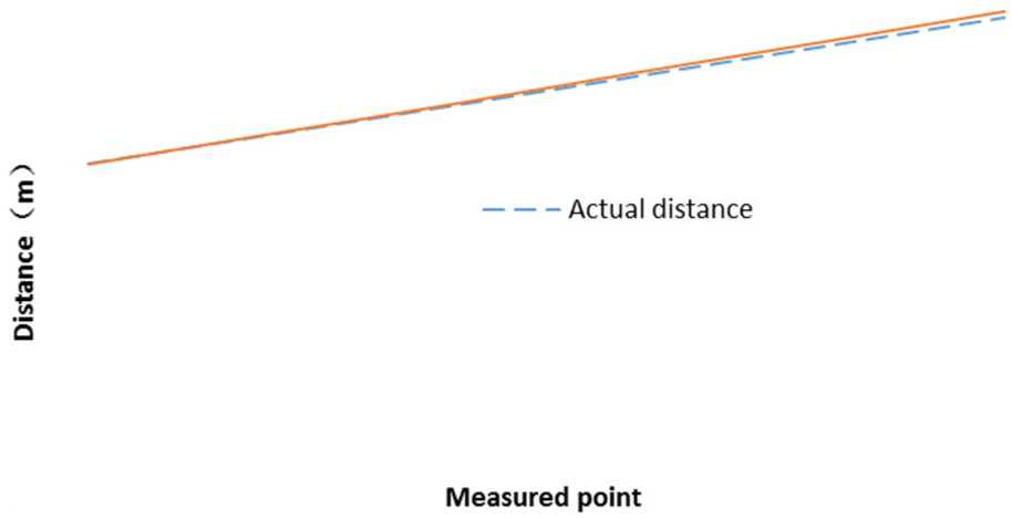
Results of measured and actual distance. The measured distance is almost the same as the actual distance.

The measurement error is less than 3%, and as the measurement distance increases, the error gradually increases.
The results show that the computation model of magnetic location is accurate and reliable and the accuracy of the detection system meets the requirement of drilling operation in SAGD dual-horizontal wells, which provides basis for further field experiment.
Field test
The super-heavy oil reservoir in Fengcheng Oilfield in Karamay, Xinjiang, is characterized by high viscosity and low formation energy. The steam huff and puff recovery has the initial high production, which declines rapidly. According to development of similar heavy oil reservoir at home and abroad, and combining with the characteristics of heavy oil in Fengcheng Oilfield, SAGD thermal recovery technology is utilized to effectively develop the super-heavy oil, which provides basis for large-scale development of super-heavy oil in Fengcheng.
Thus, the SAGD dual-horizontal well group in Zhong 37 Well block in Fengcheng Oilfield is chosen for further experiment, where the producer (production well (Well P)) is drilled with MWD technology and the steam injector (injection well (Well I)) is drilled with magnetic location technology. The drilling design requires that the vertical error between trajectory and target center is less than ±1.0 m and the planar error between horizontal trajectory and target center is less than ±2.0 m, and the spacing between two horizontal wells is 5 m. The operation technologies of this well group are as follows (Figures 10 and 11):
The MWD technology is utilized to measure and control the trajectory of lower production borehole (Well P).
After drilling Well P, Φ177.8 mm pipe string is tripped into the horizontal section. A rig is moved to the wellhead of upper steam injector (Well I) to drill the well.
Φ73 mm tube string is tripped into Well P with another rig to prepare to insert the magnetic source generator. The generator is hydraulically pumped into the tube in the horizontal section and powered through cable. The target points are set with an interval of 10 m (signed with Target 1#, 2#, 3#, etc.).
The generator is hydraulically pumped to Target 1# in Well P, and the horizontal section of Well I is drilled. The magnetic field and accelerated velocity are measured per footage of one joint with the detection system in Well I. The spacing between the detection system and the generator and their relative direction are calculated to guide drilling of steam injection well.
Again, the magnetic source generator is hydraulically pumped to Target 2# in Well P to guide drilling of horizontal section of Well I, completing position measurement and trajectory control.

Dual-horizontal wells’ collaborative operation of drill rigs—one is responsible for drilling the injection well and another is responsible for inserting the magnetic source generator in the production well.
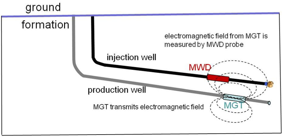
Magnetic source generator in production well produces magnetic field signal, which is measured by the detection system. The spacing between the detection system and the generator and their relative direction are calculated to guide drilling of the steam injection well.
The above steps are repeated until the horizontal section of Well I is completed.
The trajectory profiles of this well group in Figure 12 show that the maximum vertical spacing between two horizontal sections is 5.7 m, with offset of 0.7 m, minimum vertical spacing is 4.8 m, with offset of −0.2 m, and average vertical spacing is 5.12 m, with offset of 0.12 m. The trajectories of Wells I and P are basically matched in the horizontal projection, which meets requirements of the drilling trajectory design.

The trajectories of Wells I and P are basically matched in the horizontal projection, which meets requirements of the drilling trajectory design.
Conclusion
As the magnetic location technology plays an important role and shows great prospect in SAGD drilling, a new magnetic location system with intellectual property rights was developed in this article.
The magnetic location system includes mechanical parts and circuit section of the detection system. Specific structure, operating principle, and technical parameters of magnetic source generator and detection system were designed and analyzed.
The ground test results show that the source generator is powered by an alternating current of 4–7 A, the detection system can probe the magnetic field signal from the magnetic source generator 25 m away, and the measurement error is less than 3%.
The results of field experiment show the trajectories of Wells I and P are basically matched in the horizontal projection, and the measurement error is within the allowable range.
The research results of this article are of great significance to promoting the rapid application of magnetic guidance technology for SAGD in China.
Footnotes
Handling Editor: Hongfang Lu
Declaration of conflicting interests
The author(s) declared no potential conflicts of interest with respect to the research, authorship, and/or publication of this article.
Funding
The author(s) disclosed receipt of the following financial support for the research, authorship, and/or publication of this article: This work was supported from the Natural Science Foundation of China (No. 51574198).