
Abstract
The optimum gating system for manufacturing turbine housing is designed in this study, and a heater as heat source is provided to the riser, attempting to reduce its size. In the case where the runner is divided into two branches, a symmetrical gating system is adopted so that the two products could be produced in one process. Furthermore, cross-sectional shapes of the sprue, runner, and gate are designed by setting the sprue:runner:gate ratio at 1:0.9:0.6. A casting analysis is then conducted to investigate the effects of shape of the riser, sleeve material, temperature of the heater, and provision of insulation material at the top of the riser. The conditions obtained from the analysis are applied to the experiment. Hot spot defects calculated by casting simulation are reduced when sand sleeve material, straight type riser, open top sleeve, and more than 600°C of heater temperature are used. It is possible to produce a casting with almost no surface defects by adopting a riser with a size of 10–20 mm and a heater of 600°C–700°C. A casting recovery rate of 80% is achieved and, regarding mechanical properties, its tensile strength is 534 MPa, its elongation rate is 9%, and its Brinell hardness is 170 HB.
Introduction
A turbocharger system is a device that improves the charging efficiency of a mixed gas by converting the pressure energy from the exhaust gas of an engine into rotatory power for a turbine, thus improving engine output and fuel efficiency. The exhaust gas that is generated from an internal combustion engine is transferred to the turbine, and the turbine wheel rotates by the pressure of the exhaust gas. The turbine and compressor wheels are connected through an axis; thus, the rotatory force of the turbine wheel acts as a rotatory force for the compressor.1,2
Spheroidal graphite cast iron is used as the material for the turbine housing of diesel engines, while austenite stainless steel is used for the turbine housing of gasoline engines. It is not possible to fabricate a turbine housing through plastic working, and therefore, casting technology is used. The temperature of the exhaust gas exceeds 800°C, and thus, sand casting is employed.1–3
The volume of a currently produced turbine housing is considerably lower than the sum of the volumes of the sprue and riser. In addition, a turbine housing is tube-shaped, with a hollow interior, and thus, the riser is far heavier than the casting product. Therefore, the riser solidifies much later than the casting product when the molten metal is flowed into the cavity, thereby hampering production speed. The housing of a turbine has an irregular shape, with a thickness of less than 10 mm. This leads to the generation of many defects, thus adding challenges to the manufacturing process. Therefore, turbine housings are normally being cast with a recovery rate in the range of 45%–50%.4–8
The high-silicon series spheroidal graphite cast iron is easily cast and has a low manufacturing cost; therefore, it is used in exhaust manifolds and turbine housings, which are operated in a high-temperature environment. However, the high-silicon series spheroidal graphite cast iron has poor thermal resistance and requires the incorporation of an amount of chiller during casting for ensuring that a forming defect does not occur. Hence, it is difficult to use high-silicon series spheroidal graphite cast iron for products with a thickness of less than 10 mm.4,5,9,10
In this study, a plan to design a gating system for turbine housing and improve recovery rate with a sand casting process is proposed. An optimal gating system for turbine housing casting was designed, and a heater as heat source was provided to the riser, attempting to reduce its size. To minimize the volume of the riser, a riser heating method was developed, which uses a heater to induce delay in the solidification of the molten metal. A casting analysis was then conducted to investigate the effects of shape of the riser, sleeve material, temperature of the heater, and provision of insulation material at the top of the riser. The conditions obtained from the analysis results were applied to the experiment. Brinell hardness test for the casted product and the tensile test for casted Y-block were performed as part of the analysis of physical properties.
Design of gating system
The turbine housing used in diesel engines receives exhaust gas with a temperature of over 800°C. Therefore, it is manufactured with a sand casting process for spheroidal graphite cast iron. The drawing of the designed turbine housing for diesel engines is shown in Figure 1. The model, wherein a gating system was attached on two turbine housings, is shown in Figure 2. This study designs the gating system with a process that could produce two turbine housings by one casting process. This gating system has runners and gates, two of each, at the left and right. The shape of the gating system at the left and right is symmetrical, having the same shape. The molten metal is branched into two paths along the runners, at the left and right sides, while passing through the runner, and it is injected into the turbine housing through the gate.

3D modeling of turbocharger housing (unit: mm): (a) front view, (b) back view, and (c) section view.

Gating system for casting of turbine housing (unit: mm).
Because cast iron has a density of 7.8 g/cm3, which is relatively higher than that of other metals, a gating system of the compression type, wherein the cross-sectional area of the sprue is the largest and that of the gate is the smallest, was adopted. The sprue:runner:gate (SRG) ratio depending on the cross-sectional area was set to 1:0.9:0.6. As the molten metal advanced to the gate after passing through the runner, the flow rate and pressure energy increased. Once the minimum cross-sectional area necessary to inject the molten metal into the cavity of the mold was decided, the cross-sectional areas of sprue, runner, and gate could be calculated. Equation (1) was used to calculate a minimum cross-sectional area. 11 The calculated minimum cross-sectional area was 384.93 mm2
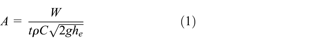
In this equation,
The injection time of the molten metal was calculated from the empirical formula of equation (2), 12 and the determined injection time was 5.73 s

The effective height was calculated from equation (3) 12 and the obtained effective height was 106.4 mm

Here,
The speed of the molten metal flow into the gate that was calculated from the effective height was around 1.44 m/s.
The cross-section areas of sprue, runner, and gate were calculated from equations (4)–(6), 12 respectively


Here, S, R, and G are SRG ratio, while
The cross-sectional area of the sprue calculated from equation (4) was 641.56 mm2, and the diameter of the sprue calculated from the above equation was 28.58 mm. The diameter of the sprue was set to 30 mm to make mold preparation convenient. The cross-sectional area of the runner calculated from equation (5) was 577.40 mm2, which was the total cross-sectional area of the runner. The cross-sectional area of one gate calculated from equation (6) was 96.2 mm2 and the total cross-sectional area of gate was 384.8 mm2.
The cross-sectional shape of the runner and gate was designed from the theoretically calculated cross-sectional area. Figure 3 shows the cross-sectional shape of the runner and gate. The thickness of the runner was 14 mm, while the height of the gate was 9 mm. The width of the runner and the gate was 12 mm. A gradient of 5° was set to restrict the turbulent flow of the molten metal and to easily release the product after solidification. The cross-sectional area of the runner, calculated from the designed cross-sectional shape, was 149.6 mm2. This value was for one cross-sectional area of the runner; thus, the total cross-sectional area for the four runners was 598.5 mm2. The area per gate calculated from the designed cross-sectional shape of the gate was 100.1 mm2. The cross-sectional areas for sprue, runner, and gate were designed slightly smaller than the areas calculated from the equations. The SRG ratio of the designed gating system was 1:0.85:0.57. The lengths of the runner and gate were designed as short as possible to raise the recovery rate. The volume of the gating system was 145,067 mm3 and its weight was 1.14 kg.

Section view of runner and gate (unit: mm).
Figure 4 shows the three types of risers that would be adopted in the turbine housing. The shapes of the riser were linear, taper, and step. The optimum condition was obtained from the solidification analysis. The riser was installed at the portion where the thickness of the product was the largest. The height of the riser was 83 mm, the same as that of the sprue. One riser was installed at the left turbine housing, while another was installed at the right turbine housing. The volume of the linear riser was 52,124 mm3 and its weight was 0.410 kg. The volume of the taper type riser was 85.330 mm3, while its weight was 0.671 kg. Meanwhile, the volume of the step type riser was 108,252 mm3 and its weight was 0.799 kg.

Riser shape (unit: mm): (a) straight type, (b) taper type, and (c) step type.
Casting simulation
Condition of simulation
If the size of the riser is large, it appropriately compensates shrinkage during the solidification of the casting and ultimately reduces defects, but the recovery rate would be reduced. In order to increase the recovery rate, the size of the riser should be diminished. However, a small riser would result in quick solidification by heat transfer to the outer side and, consequently, the riser would not perform its role properly. The size of the riser was reduced to raise the recovery rate, and heaters were installed around the riser. Because the heaters heated up the riser while the casting was solidified, the riser could be solidified later than the casting even if the size of the riser was small.
Figure 5 presents the cut area of the heating system for the riser. It includes a sleeve, top insulation, and heater near the riser, which maintain the necessary temperature. Table 1 presents the computer-aided engineering (CAE) condition to determine gating system. This investigation evaluated the effects of riser type, heater temperature, and sleeve material–with and without top insulation—to increase the recovery rate of the product. The types of riser are straight, taper, and step. The sleeve materials are steel and sand. The temperatures of the heater are 400°C, 500°C, and 600°C.

Construction of riser heating system for riser size minimizing.
Simulation conditions to determine gating system.

The analysis was carried out for a total of seven conditions. CAE conditions 1 and 2 are the comparisons regarding sleeve materials, while conditions 3 and 4 are the comparisons for the implementation of top insulation. Conditions 5, 6, and 7 refer to the comparisons for heater temperatures.
The recovery rate is defined as the value obtained by dividing the weight of the casting by the sum of the weight of the gating system, riser, and casting product; that is, as the weight of the gating system and riser is decreased, the recovery rate would be increased. When the linear riser was used, the recovery rate was 83%, while with the taper type riser, the recovery rate became 81%. With the step type riser, the recovery rate was 79%, which was the lowest among the three tested risers.
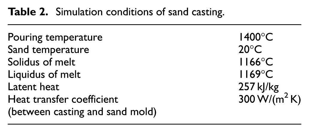
Table 2 shows the conditions of sand casting simulation with MAGMA software. The temperature of the mold (sand) was set to 20°C. The heat transfer coefficient between the casting and sand mold was calculated by the temperature difference method. The medium value was about 300 W/(m2 K).
Simulation conditions of sand casting.
Casting simulation was conducted with the MAGMA 5 software (GmbH, Aachen, Germany). MAGMA’s mesh partitioning method is the finite volume method (FVM). The results were 907,350 meshes on the metal cell and 18,875,930 meshes on the control volume, which is the material group.
Results of simulation
Figure 6 illustrates the filling mode while the molten metal was charged into the cavity of the mold. The transparent part displays the condition where the molten metal was not filled into the cavity, while the yellow portion shows the molten metal filled into it. The percentage value refers to the volume of the molten metal filled into the cavity, while the time shows the duration of filling of the molten metal. When the molten metal was filled at 25%, it was injected from the sprue, passed through the gate, and flown into the product; there would be turbulence to some extent. Because the molten metal inflow from the sprue was freely dropped, the speed of inflow into the gate could be considerably high, resulting in a significant turbulence. The turbulence was not substantial because the location of the gate was 30 mm from the bottom of the sprue. When the molten metal touched the bottom of the runner, the speed was reduced and the molten metal could be flown into the gate. The filling speed of the molten metal at the gate, calculated from the equation, was 1.44 m/s. When the molten metal was charged at 55% into the cavity, the turbulent flow was converted into laminar flow, and then the flow would be stabilized. The time to fill the molten metal at 100% was 5.186 s, which was faster than the calculated value (5.73 s) by 0.544 s. When the molten metal having a temperature of 1400°C was completely filled into the cavity, there was a temperature loss from the surface of the product at around 90°C. Because the theoretical temperature of the liquid phase line of the Gray Casting Ductile (GCD) 600 material was 1169°C after the molten metal was completely filled into the mold cavity, solidification was executed while the molten metal was static. Therefore, the designed gating system could be suitable for the casting process of turbine housings.

Filling behavior of turbine housing for sand casting.
The riser types included a straight type, which was adopted in conditions 1 and 2, as given in Table 1, and a taper type, which was adopted in conditions 3 and 4. The sleeve materials included steel, which was adopted for condition 1, and sand, which was adopted for conditions 2 to 4. The heater temperature was maintained at 700°C. In addition, the insulation material at the top of the riser was adopted only for condition 3. The pouring temperature of casting (GCD 600 in the MAGMA database) was 1400°C. The solid and liquid temperatures of GCD 600 were 1166°C and 1169°C, respectively.
Figure 7 shows the solidification analyses for condition 1 (steel sleeve) and condition 2 (sand sleeve). With respect to condition 1, which had steel as the heating material for the riser and a solidification rate of approximately 10%, the solidification of the riser was almost completed at a lower temperature than the solid-phase temperature of 1166°C, as shown in Figure 7(a). However, with respect to condition 2, which had sand as the heating material for the riser, the riser and product were not isolated till a solidification rate of approximately 70%, as shown in Figure 7(b); thus, the sand sleeve in condition 2 could yield a better riser effect than the steel sleeve. Therefore, the sand sleeve exhibited a better performance with a good recovery rate when compared with the steel sleeve. Figure 8 depicts the solidification rate relative to solidification time for conditions 1 and 2. The increase in solidification time when a sand sleeve was used exceeded that of the steel sleeve, although the solidification modes were almost identical. When a sand sleeve was used, the solidification of the riser was delayed, and this occurred after riser solidification with a steel sleeve. Figure 9 shows the distribution of the hot spot, calculated from the solidification analysis of the product and the riser, and analyzed under conditions 1 and 2. Both models show the solidification modes independently, with the product and riser parts separated. The final solidified portion is presented inside the product expecting a shrinkage defect.
Solidification analysis for sleeve materials: (a) steel and (b) sand.

Relationship between solidification rate and time according to sleeve material (CAE condition 1: steel, CAE condition 2: sand).
Hot spot phenomenon analysis for sleeve materials: (a) steel and (b) sand.
Figure 10 includes the solidification analysis results of condition 3 (top insulation) and condition 4 (no top insulation). As shown in Figure 10(a), solidification progresses toward the end of the riser if there is insulation at that place. When the solidification rate corresponded to 60%, there was a difference in the solidification pattern based on the presence of insulation material at the top of the riser, as shown in Figure 10. Figure 11 shows the solidification rate relative to the solidification time for conditions 3 and 4. The solidification modes were similar with respect to solidification time. However, when the insulation material was applied at the top of the riser (condition 3), the solidification was a little faster than without the insulation material (condition 4). Figure 12 depicts the hot spot distribution for conditions 3 and 4. The calculation results under conditions 3 and 4 indicated that the product and riser were separated and solidified independently, and the final solidified part existed inside the product with the expectation of a shrinkage defect.

Solidification analysis (a) with and (b) without top insulation.

Relationship between solidification rate and time with (CAE condition 3) and without (CAE condition 4) top insulation.

Hot spot phenomenon analysis (a) with and (b) without top insulation.
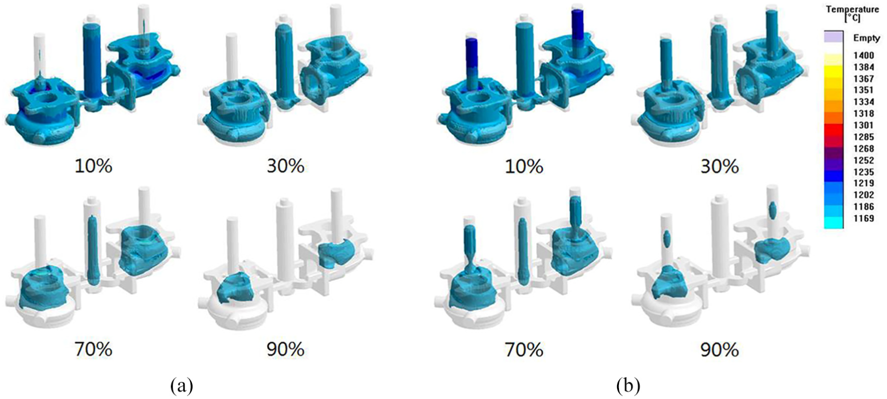
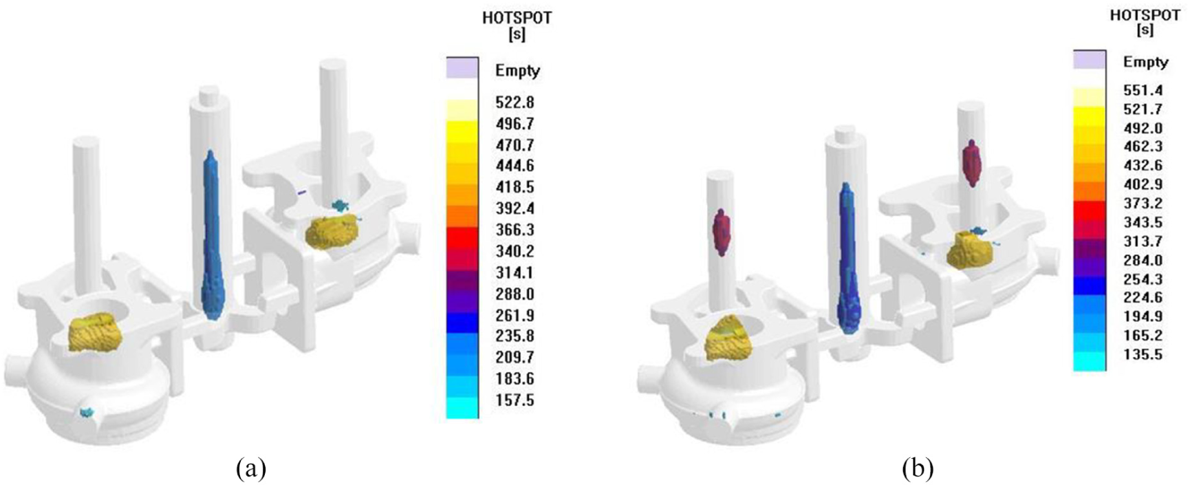
Figure 13 shows the solidification results for conditions 5 (Heater temperature: 400°C), 6 (Heater temperature: 500°C), and 7 (Heater temperature: 600°C). A step-shape riser and a sand sleeve were used. Insulation materials were applied at the top of all risers. As shown in Figure 13, in the cases where the solidification rates corresponded to 10% and 30%, with the sand sleeve, the riser temperature increased as the heater temperature increased. With respect to the overall solidification mode, it moved from the product to the end of the riser, as shown in Figure 13. Therefore, in the case of the sand sleeve, the solidification progressed from the product to the end of the riser, even if the heater temperature decreased, and thus the molten metal that was short in the product part could be fed by the riser. Figure 14 shows the solidification rate relative to time in conditions 5, 6, and 7. The overall solidification modes exhibited similar curves. The solidification time was almost the same, with a solidification rate of 70%, until approximately 200 s. However, the solidification time for the same solidification rate increased as temperature increased in the sand sleeve and heater. The final solidification time increased and corresponded to 615 s for condition 5, 737 s for condition 6, and 840 s for condition 7. This was because the heater temperature increased in such a manner that final solidification was delayed in the case of the sand sleeve. Therefore, it is necessary to reduce the heater temperature for the sand sleeve. In addition, condition 5 would be the most beneficial from the energy saving aspect. Figure 15 depicts the hot spot distribution calculated using conditions 5, 6, and 7. A hot spot under condition 5 is generated at the boundary of the riser, and the product below the riser creates a shrinkage defect. However, in the cases of condition 6 (heater temperature at 500°C) and condition 7 (heater temperature corresponding to 600°C), solidification progressed from the product to the riser if the heating temperature for the sand sleeve increased, and the hot spot in the product decreased. Therefore, the most favorable condition to remove the shrinkage defect inside the product corresponded to condition 7, with a heater temperature of 600°C and the adoption of a step type riser.
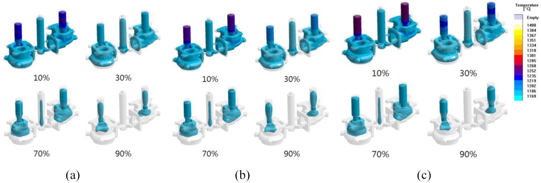
Solidification analysis for heater temperature: (a) 400°C, (b) 500°C, and (c) 600°C.

Relationship between solidification rate and time according to heater temperature (CAE condition 5: 400°C, CAE condition 6: 500°C, and CAE condition 7: 600°C).

Hot spot phenomenon for heater temperature: (a) 400°C, (b) 500°C, and (c) 600°C.
Experiment
Condition of experiment
Spheroidal graphite cast iron GCD 600 molten metal, which is used in turbine housing, was prepared to perform the casting experiment. Table 3 lists the experimental conditions for manufacturing the turbine housing in order to verify the mold design that was proposed in the theoretical analysis. Experimental conditions 1 to 3 comprised different linear risers, with heaters only at the left side. Condition 4 comprised a linear riser having a diameter of 20 mm, with heaters at the left and right sides. Condition 5 refers to the linear type riser having a diameter of 20 mm, which was used without a heater at both the left and right sides. Conditions 6 to 8 comprised different heater temperatures, with only one heater at the left side on the step type riser.
Experimental conditions.

CAE: computer-aided engineering.
The key parameters for the experiments were set with the diameter of the riser (10–30 mm), heating provision for the riser, and temperatures of the heater at 400°C, 500°C, 600°C, and 700°C. Sleeve temperature means the temperature that reaches the established temperature of the heater. The mold design was verified using the commercial S/W of MAGMA.
Figure 16 depicts the heating system, where the heater was installed on the sand sleeve when the diameter of the riser corresponded to 30 mm. Figure 17 shows the sand casting mold assembly for the turbine housing experiment. The two-core mold for the turbine housing was assembled in the casting system mold. The heater was installed on the product at the right side, while the assembled exterior of the mold without a heater is shown at the left side. Sand coated with hardened material was used as the mold material.

30-mm-diameter heating equipment for riser temperature control with sand sleeve.

Sand mold of turbine housing: (a) core mold for turbine housing and (b) casting system mold.
Results of experiment
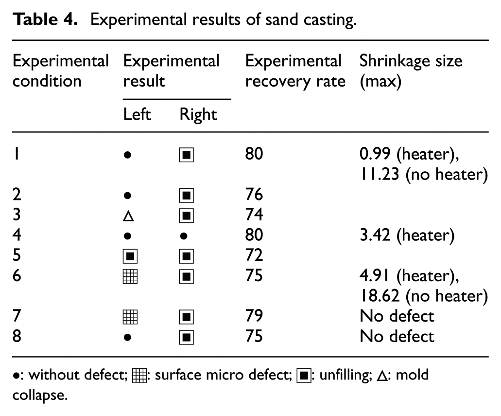
Table 4 presents the experimental results for the turbine housing fabricated by sand casting. Experimental conditions for conditions 1–5 present the surface characteristics of the product based on the heating of the riser when the diameter of the riser corresponded to the range of 10–30 mm. A forming ( ) and surface defect (
 ) were not observed if the sleeve that heated the riser was heated to 700°C (conditions 1–4). However, the surface defects were obvious when the riser was heated to 400°C and 500°C, as shown in conditions 5 and 6. When the effect of the arrangement of the cavity was examined, there was no defect found from the cavity heated to 700°C, irrespective of its arrangement in conditions 1–4. Furthermore, no-forming defect was generated in the cavity (condition 5) where heating was not implemented. In conditions 6 and 7, micro-surface defects were found from the surface of the cavity where riser was heated to 400°C and 500°C. In contrast, no forming occurred from the cavity without heating. In condition 8, the cavity heated to 600°C did not generate any defects. The above experimental results indicated that when the recovery rate was over 70%, a riser with a diameter in the range of 20–30 mm and temperature exceeding 600°C were necessary conditions for optimal results. When the diameter of the riser corresponded to 30 mm and riser temperature abruptly increased to 700°C, the inner wall of the riser became brittle, leading to collapse (
 ).
).
Experimental results of sand casting.
•: without defect;  : surface micro defect;
  : unfilling;
  : mold collapse.
The recovery rates of the design and the experiment differed. The reason for the difference could be attributed to the working environment, wherein an accurate quantity of the molten metal could not be controlled, owing to worker errors.
Figure 18 shows two turbine housing parts simultaneously manufactured by a one-time injection. A filling phenomenon was not found in the part in which heating was not implemented in the riser (photograph at the left). Therefore, it is necessary to heat the riser to obtain a product with a recovery rate that exceeds 70%.

The turbine housing casted by experiment condition 1: (a) plan view, (b) front view, and (c) back view.
Table 5 provides the mechanical properties of the turbine housing. Tensile test specimens were prepared per the specifications in ASTM E8M. These specimens were subjected to heat treatment at 950°C for 2 h. Following austenization, the specimens were cooled inside an electric oven at 550°C for 2 h. The tensile strength, elongation, and Brinell hardness were measured as 534 MPa, 8%, and 170 HB, respectively. These values changed after the heat treatment, and the tensile strength, elongation, and Brinell hardness then corresponded to 615 MPa, 5%, and 217 HB, respectively.
Mechanical properties of turbocharger housing part.

Conclusion
A gating system was designed to cast a turbine housing. A cylindrical heater was adopted to minimize the size of the riser. The obtained results are summarized below:
From the casting analysis, the linear and taper-shaped risers were found effective in delaying solidification. Furthermore, as a material for sleeve, sand was better for delaying solidification than iron. When the temperature of the heater was set at 600°C, the hot spot defect was reduced. In addition, the hot spot defect was decreased if insulation material at the top of the heater was not applied.
A good casting product with almost no surface defects could be obtained by implementing a heater at 600°C–700°C on the riser, with diameters between 10 and 20 mm. When a heater at 700°C was implemented on the riser having a diameter of 30 mm, the model would be collapsed. On the contrary, if the temperature of the heater was lower than 600°C, a casting defect, such as having no filling or a large surface defect, was generated.
Hot spot distribution calculated by MAGMA soft was reduced when sand sleeve material, straight type riser, open top sleeve, and more than 600°C of heater temperature were applied.
The optimized parameters for manufacturing turbine housing without defects are a diameter of Ø20 of the straight type riser, sand sleeve, and 700°C of the heater temperature. An 80% recovery rate of the castings is obtained from these parameters.
Footnotes
Handling Editor: Jia-Jang Wu
Declaration of conflicting interests
The author(s) declared no potential conflicts of interest with respect to the research, authorship, and/or publication of this article.
Funding
The author(s) disclosed receipt of the following financial support for the research, authorship, and/or publication of this article: This work was supported by the National Research Foundation of Korea (NRF) grant funded by the Korean government (MSIP) through the GCRC-SOP (No. 2011-0030013). This work was also supported by the National Research Foundation of Korea (NRF) grant funded by the Korea government (MSIT) (No.2017R1A2B4007884). This work was also supported by the National Research Foundation of Korea Grant funded by the Korean Government (NRF-2017R1C1B5017242).