
Abstract
Bottom-up gated filling system was performed to produce worm wheel through a sand casting of zinc alloy. It was a symmetrical design in which two worm wheels were cast at once, the worm wheel was erected in the direction of gravity and had a gating system in which molten zinc alloy were poured from below. The recovery rate of the designed mold cavity was 60%. Casting analysis was performed to check that the worm wheel was sequentially filled without turbulent flow as the molten zinc alloy passed through the gate. Though the speed of the molten zinc alloy initially poured was unstable, it became stabilized while maintaining a constant speed due to the continuous inflow. The results of directional solidification were confirmed. An integrated mold cavity pattern was fabricated by 3D printer, and sand mold were manufactured accordingly. A sound worm wheel without defects could be fabricated through sand casting.
Introduction
Among the various process of manufacturing mechanical parts, the casting is a process in which a molten metal is usually poured into a mold, and then allowed to solidify. Its main advantage is that it can freely manufacturing complex shapes that would be otherwise difficult. Sand casting, among the casting process, has the lowest manufacturing cost because the material of the mold is sand. However, there are general disadvantages such as low precision of shape and low mechanical properties due to pores generated inside the part.1–6 In casting, molten metal is poured in not only as much as the desired shape, but also to the gating system (downsprue, runners, and gates), which is a path that makes the molten metal flow to the position of the desired shape, and till the risers. In normal sand casting work, the gating system and riser are not appropriately designed, so their weight is greater than the weight of the desired shape. In addition, the hollow cavity in sand mold is not designed close to the desired shape but is designed in an approximate shape for casting.6–10 After solidification, excess removal of the gating system and risers as post-casting process to cut the casting according to the desired shape are essential processes of sand casting. That means, more materials are wasted than materials desired shape, and the time and cost for the post-casting process are quite large, which is the biggest disadvantage of sand casting.1–13 To reduce the amount of wasted material, it is necessary to design a gating system suitable for the desired shape and to verify and supplement the gating system through casting simulation.
Zheng et al. 14 used casting numerical simulation technology to optimize the casting process scheme of a higher-quality water-meter shell. Nimbulkar and Dalu 15 optimized the gating system using casting simulation software, and compared the simulated result and experimental results, to reduce rejection rate. Dučić et al. 16 presents a methodology of optimization of the gating system for sand casting using the genetic algorithm. Jin et al. 13 designed the optimum gating system in sand casting for manufacturing turbine housing of turbocharger. Seo et al. 17 proposed mold design technology for a full-spade carrier housing to increase recovery rate of exceeds 70%. Kumar et al. 18 reduced the flow and surface-related defects by revising the existing gating system of the bearing block and pump diffuser casing using casting simulation software.
Worm gears are screw action gears that have less vibration and noise compared to general gears and can achieve a significant reduction ratio. 19 For casting of zinc alloy, approximately more than 80% are cast by hot chamber die casting. Relatively little is gravity casting used in sand mold. Zamak is the hypoeutectic alloys that they are used to produce a wide range of components within numerous industrial applications. Zamak 3 is a family of alloys with 96% zinc and alloying elements of 4% aluminum and 0.03% magnesium.1,20–23
In order to manufacture Zamak 3 worm wheel with a low-cost process, the challenge was to apply the sand casting process. To reduce the amount of wasted material, the worm wheel shape in mold cavity was designed by excluding only the tooth part. In addition, a gating system suitable for the shape of a worm wheel (circular disk) was designed, and the size of risers was minimized and the number of risers was reduced as much as possible. The recovery rate of the mold cavity designed through this process is 60%. In case of high recovery rate, it is an essential process prior to mold making and is analyzed through simulation. Casting possibility was checked from the results of filling and solidification using a casting simulation program. To reduce the material and manufacturing cost of wood pattern, a mold cavity pattern of PLA in which the worm wheel, gating system, and riser were integrated was fabricated using a 3D printer. The pore distribution was confirmed through CT analysis. Mechanical properties and microstructures were analyzed, and the same analysis was performed after heat treatment. The casting method presented in this study was compared with the traditional method with respect to the production process, mechanical properties, and porosity.
Design
Modeling and structure analysis of worm wheel
The grooved worm wheel to be manufactured in this study is used for the steering device to change the direction of the boat. Since the worm wheel is operated in a seawater environment, a zinc alloy with excellent corrosion resistance is used. Figure 1 shows the 3D shape of the worm wheel. The designed worm wheel has a diameter of 153.4 mm and a thickness of 5.3 mm. A lever was coupled to the central hole of the worm wheel. When the operator rotates the lever, the worm disk is driven, and stress concentration is generated around the hole due to the moment. Therefore, the portion around the hole is a bit thicker 28.8 mm. Unlike normal worm wheels, the worm wheel teeth are grooved rather than protruding. Therefore, the outer rim of the worm wheel has a groove into which a belt can be inserted like a pulley. Since the tooth of the worm wheel must have high dimensional accuracy, the tooth was excluded from the casting shape design. The volume of the worm wheel was 139,800 mm3, and the weight calculated by applying the density of zinc was 0.998 kg.

Three dimension modeling of the grooved worm wheel (unit: mm).
Structural analysis of the designed worm wheel was performed using ANSYS Workbench. Zinc was selected from the engineering data, Young’s modulus of Zinc was 99.5 GPa, and Poisson’s ratio was 0.25. The number of generated meshes was 67,000. Among the boundary conditions, the constraint was set as a cylindrical support condition in which the hole in the center was supported. As for the load condition, the condition was set to as the worm wheel to receive a moment in the axial direction. The length from the hole to the lever handle was approximately 180 mm, and the required force for rotation was approximately 200 N, so an axial moment of 36 N m was given. Figure 2 shows the results for equivalent stress and deformation. The highest stress (28 MPa) was generated in the central hole, and the highest deformation (0.025 mm) was generated in the outer rim in contact with the worm. The structural analysis results showed that when the worm wheel was driven, it was in a state of complete elastic deformation.

Structural analysis results of the worm wheel: (a) equivalent stress and (b) deformation.
Gating system design
To manufacture the worm wheel except only the tooth by the sand casting process, the gating system design was performed. The mold cavity design of the worm wheel is presented in Figure 3. As a bottom-up gated filling system, a gating system of symmetrical type from the downsprue was designed in which two worm wheels were cast at once. The two worm wheels were erected in the direction of gravity. The runners were arranged left and right from the downsprue. The runner part connected to the downsprue was straight, and the part connected to the worm wheel was curved. Two gates each were placed on the right runner and the left runner, respectively. In casting simulation, the pouring basin is not installed, but the inlet is set at the top of the downsprue. In real casting experiment, pouring basin is installed for smooth molten alloy pouring.

Mold cavity design with a bottom-up gated filling system for casting of the worm wheel (unit: mm).
For large castings, tapered downsprue is usually applied. In case of small castings, it is known that the amount of air flowing into the mold is small even when a straight downsrpue is applied. The downsprue was designed in a straight type.13,24–26 The downsprue is cylindrical and has a diameter and length of 20.0 and 255.0 mm, respectively. The length of the runner is 424.4 mm. The lengths of inner gates and outer gates are 9.0 and 11.5 mm, respectively. The cross-sectional shape of the runner, and gates can be seen in section A-A, section B-B, and section C-C of Figure 3. The cross-sectional shape of the gates is triangular, and the cross-sectional shape of the runner is designed to be trapezoidal. Zinc has a specific gravity of 7.14, which is heavy compared to other metals. Therefore, the cross-sectional area calculation formula of the pressurized method with the largest downsprue cross-sectional area and the smallest gate cross-sectional area was applied. The ratio of SRG (downsprue:runner:gate) was set to 1.00:0.75:0.75. The cross-sectional area of the downsprue was 314.1 mm 2 and the cross-sectional area of the runner was 235.0 mm2. The cross-sectional area of a single gate was 58.7 mm2, and the cross-sectional area of four gates was 234.8 mm2.
As the molten zinc alloy flowed down through the downsprue, it traveled to both runners. Then it flowed along the runner and flowed into the two gates. As the molten zinc alloy flowed into the groove of the outer rim of the worm wheel by the two gates, filled the worm wheel, and finally reached the risers.
The riser principally compensates for the shrinkage when the casting solidifies and informs that the molten zinc alloy is finally poured. Therefore, the position of the risers were set at the highest position of the outer rim of the worm wheel. The diameter of the riser was 20 mm and the length of the riser was 45.6 mm, which was the same as the height of the downsprue. One riser was placed on the left worm wheel and the right worm wheel, respectively. The weight of the two worm wheels was 1.996 kg, the weight of the gating system was 1.205 kg, and the weight of the two risers was 0.119 kg. The combined total weight of these was 3.320 kg. The recovery rate obtained by dividing the weight of the two worm wheels by the total weight is 60.1%.
Fabrication of mold cavity pattern by 3D printer
3D printer is used instead of a wooden pattern, it is possible to create a hollow cavity shape in which the desired shape, gating system, and risers are integrated. In addition, the hollow cavity of the desired shape can be made close to the shape of the actual product. There is no need to use expensive wood, and it can be replaced with inexpensive plastic materials. A 3D printer was used to fabricate the mold cavity pattern of the one-piece (worm wheels, gating system, and risers combined) (As shown in Figure 3 at once). Fused deposition modeling (FDM) 3D printer was used, and PLA was used for the filament. To make the worm wheel surface smooth, a nozzle with a diameter of 1.75 mm was used. The printing speed was set to 40 mm/s, the nozzle temperature was set to 200°C, and the bed temperature was set to 60°C. Figure 4 shows a mold cavity pattern printed with a FDM 3D printer. The output was completed perfectly as the shape in Figure 3.

Mold cavity pattern manufactured by FDM 3D printer.
Condition of simulation and experiment
To cast the worm wheel except only the tooth by the designed gating system with 60.1% recovery rate, the casting simulation is certainly performed. MAGMA 5.1 S/W was used to perform casting analysis. In the MAGMA Engineering data, the casting material was ZnAl4Cu1, and the mold material was green sand. The casting temperature was set at 520°C, which was higher by 131°C than the liquidus temperature (389°C), and the initial temperature of the sand mold was set at 40°C. The insert pressure was set to 11.9 mbar, and molten zinc alloy was poured at a height of about 50 mm. The time for the casting to fill 100% of the mold cavity was set to 9 s. Figure 5 show physical model for casting simulation of the worm wheel. The diameter of the inlet was set to 12 mm. All other process conditions were applied same as the actual experimental conditions. The number of meshes of the metal cell (cast) was 465,300, and the number of meshes of the control volume, which was a material group (mold), was 10,357,100. The heat transfer between the material groups used in the analysis was set at 7000 W/m2K between ZnAl4Cu1 and green sand and 1000 W/m2K between the top mold and the bottom mold to increase the heat transfer effect with the inside of the mold. Control equations of filling simulation of casting process mainly consists of mass conservation, Navier-Stokes equation, energy conservation, volume of fluid. 27

Physical model of casting simulation for worm wheel.
Zamak 3 alloy was used in casting experiment. The main alloy composition of zamak 3 was 4.0 wt.% aluminum and 0.8 wt.%. Figure 6 shows the fabrication process of sand mold. The mold cavity pattern of the one-piece (worm wheel, gating system, and riser combined) which is printed by 3D printer in Figure 4 was used to prepare the core molds. The core molds were made first and it were set it up in the direction of gravity. A frame molds were fabricated by putting the core molds in a square frame and completely covering it with casting sand. The pouring temperature was set to 520°C. Figure 7 shows an image where molten zinc alloy was poured into the fabricated sand mold. Pouring basin is installed for smooth molten zinc alloy pouring. Molten zinc alloy was poured down to the bottom of the pouring basin. After 24 h, the sample was removed from the sand mold. After shot peening, a post-casting process was performed to remove the gating system and risers.

Fabrication process of sand mold.

Sand mold poured with molten zinc alloy.
Tensile specimens were prepared according to ASTM E8M subsize. The tensile test was performed at a cross head speed of 3 mm/min. The hardness was measured repeatedly five times by setting the indentation load to 500 g with a micro-Vickers hardness. For heat treatment, solid solution treatment was performed at 360°C for 1 h, cooled in water, and then aging treatment was given at 100°C for 10 h. Microstructures of casted worm wheel were analyzed with optical microscope and the pore distribution was confirmed through CT analysis.
Results of simulation and experiment
Simulation results
Figure 8 shows an analysis result showing the temperature change while the molten zinc alloy was poured into the mold cavity. The transparent color is the state in which the molten zinc alloy was not filled with a cavity, and it is expressed in as-sorted colors depending on the temperature of the molten zinc alloy. Percentage values indicate the amount by which the molten zinc alloy was filled with the cavity. After the molten zinc alloy was poured into the downsprue, it flowed smoothly into the gate while moving to both runners. As the molten zinc alloy passed through the gate, the worm wheel was sequentially filled without turbulent flow. If the number of the gates or gate size are increased, interference will occur between the gates, as well as between the gate and worm wheel. This means that there are limitations in the dimensions and number of the gate with respect to the design.

Simulation result. Filling pattern of molten zinc alloy in mold cavity.
The greatest temperature loss occurred at the outer rim of the worm wheel during flowing. However, the temperature of this part was approximately 425°C, which was 35°C higher than the liquidus temperature (389°C) of the ZnAl4Cu1 material, so it was expected that there will be no problems such as defects. If the process is designed under the condition that the groove part of the outer edge is also subjected to post-casting processing, the amount of temperature loss in the outer rim part can be further reduced because the groove is removed from the casting modeling. From the results in Figure 8, the worm wheel started solidifying after the molten zinc alloy was filled into the mold cavity. Therefore, the designed gating system was a suitable solution for the worm wheel.
Figure 9(a) shows the analysis result of the speed at which the molten zinc alloy passed through four gates. 1-1 and 2-1 were the inner gates close to the downsprue, and 1-2 and 2-2 are the outer gates. The speed of the molten zinc alloy flowing into the gate changed significantly at the beginning, and then stabilization while being maintained in the range of 0.55–0.65 m/s. The gates of 1-1 and 2-1 had a low initial in-flow rate, whereas the gates of 1-2 and 2-2 had a high initial inflow rate. Figure 9(b) shows the speed distribution when the worm wheel was 50% filled and the speed distribution when the worm wheel was 100% filled. The velocity distribution when the worm wheel was 50% filled with molten zinc alloy was approximately 0.5 m/s at the gate and approximately 0.2 m/s at the worm wheel. The velocity distribution when the worm wheel was 100% filled with castings was 0.2–0.3 m/s at the gate and about 0.1 m/s at the worm wheel.

Simulation result. Filling velocity of molten zinc alloy in mold cavity: (a) time versus velocity graph at four gates and (b) velocity when molten zinc alloy is 50% filled and 100% filled in worm wheel.
Figure 10 shows the analysis result of the air entrapment when the molten zinc alloy was poured into the mold cavity. If the amount of air entrapment is more than 30%, there is a high possibility that the porosities are generated due to the inflow of air. As shown in Figure 10(a), the air entrapment value flowing into the right worm wheel was larger than that of the left worm wheel. The air entrapment of the left worm wheel was approximately 2%, but the right worm wheel was approximately 6%. The air entrapment of the right worm wheel was about three times higher than that of the left worm wheel. As can be seen from range 30%–78% results in Figure 10(b), it was unlikely to have air entrapment because the value was less than 30%. At the X-ray range 0%–30% of air entrapment, the amount of the worm wheel was high, as shown in Figure 10(a). However, the air entrapment at the riser was more two times high. Thus, directional solidification could be induced. But, it was difficult to determine whether shrinkage porosities occur from this results.
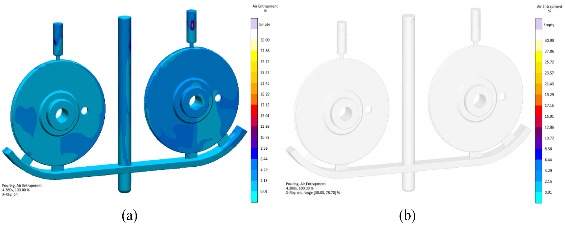
Simulation result. Air entrapment in mold cavity: (a) X-ray (range 0%–30%) and (b) X-ray (range 30%–78%).
Figure 11 shows the results for the solidification process of the molten zinc alloy in the mold cavity. The amount of fraction liquid is expressed by color, and the transparent color means that it solidified into a solid. It was found that the worm wheel was solidified first, and then the gating system was solidified. The worm wheel solidified first at the thin outer rim, and the edge in contact with the gates solidified later. The thick central part solidified late, and the part closed to the gates solidified a little later even at this location.

Simulation result. Solidification process of molten zinc alloy in mold cavity.
Figure 12 shows the analysis results for hotspot and porosity. Hotspots occur at the locations mostly where the solidification rate was slow. Porosity usually occur at the hotspot. If a specific location is thicker than other locations, hotspots and porosity are more likely to occur. As can be seen from Figure 12(a), the location where the hotspot occurred was around the center hole of the worm wheel. And it was generated at the part where the gate and the runner were in contact, the downsprue and the riser. As can be seen from the fraction liquid results in Figure 11, solidification was delayed because the portion around the central hole of the worm wheel was thicker than other locations, and hotspots also occurred at this location. And the outer rim of the worm wheel close to the gate also solidified late, resulting in small-sized hotspots. Although hotspots occurred at all locations surrounding the hole, porosity showed slightly different results. The porosity result in Figure 12(b) showed that the porosity occurred only at the top of the hole. In order to remove solidification defects molten metal was be supplemented into the top of worm wheel by design of the risers. This avoided the shrinkage porosity defect, although the hot spot in the worm wheel was not removed. If the size of the riser was increased, directional solidification was not performed during the solidification of the worm wheel and thus the shrinkage porosity defects could be present. Since the downsprue, runner, gates, and risers are the parts to be removed, it is ignorant even if hotspots or porosity occur.

Simulation result: (a) hotspot and (b) porosity distribution after solidification.
Experimental results
Figure 13 shows an image of a worm wheel prepared by sand casting and an X-ray image obtained by computerized tomography (CT) scanning. After casting, the gating system and risers were removed. The size of the riser was small and the number of gates was also small, so it was easy to remove them from the worm wheel. The worm wheel had no external defects and came out in a solid form. Contrary to the analysis results of hotspot and porosity in Figure 12, porosity was not confirmed in the periphery of the central hole in the X-ray image.

Casted worm wheel: (a) worm wheel with gating system and risers removed and (b) X-ray image.
Figure 14(a) shows the micro-structure of a casted zinc alloy (zamak 3) worm wheel, and Figure 14(b) shows the microstructure with heat treatment added. Primary α-Zn phases which is surrounded by eutectic phases (α + β) were observed. Evolution of the eutectic phases after heat treatment was clearly observed. Table 1 shows the mechanical properties of the worm wheel manufactured by sand casting. The yield strength and tensile strength were 155 and 197 MPa, respectively, and the elongation was 4.5%. The Vickers hardness was 75 HV. After heat treatment, the yield strength and tensile strength slightly increased, and the elongation decreased slightly.
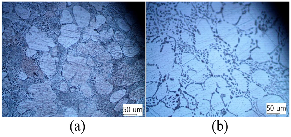
Microstructures of a zinc alloy (zamak 3) worm wheel: (a) as cast and (b) heat treatment.
Mechanical properties of casted worm wheel.

Figure 15 compares the post-casting process between the bottom-up gated filling system method as this study and the top-down filling system method as conventional casting. In the bottom-up gated filling system, two worm wheels are casted through one process, and in the top-down filling system, one worm wheel is casted through one process. The recovery rates of the bottom-up gated filling system and the top-down filling system are 60% and 28%, respectively. In the case of bottom-up gated filling system, post-casting processing is that risers and gates was cut, and only the surface of the worm wheel was machined. The post-processing time is less than 15 min, and the weight of the material removed is 1.327 kg. In the case of top-down filling system, since casting is conducted in a shape thicker than the thickness of the worm wheel, the amount of material removed is large. 2.564 kg of material is removed, which is 2.57 times the weight of the worm wheel. The post-processing time is more than 35 min. Compared with the top-down filling system, the recovery rate of the bottom-up gated filling system increased by about 32.1%, which is a great value. The material used to cast two worm wheels is 3.382 kg for the bottom-up gated filling system and 7.124 kg for the top-down filling system. The cost of casting the worm wheel can be sharply decreased because the loss of material is reduced. If the top-down filling system was applied in the casting industry with casting the worm wheel, productivity increased, cost could be decreased. Tensile strength and elongation of worm wheel casted by top-down filling system is 178 MPa and 3.5%. This is a slightly lower value than a worm wheel casted by bottom-up gated filling system. The specific data mentioned above are listed in Table 2.

Comparison of post-casting process in: (a) bottom-up gated filling system and (b) top-down filling system (conventional casting).
Comparison of specific data in bottom-up gated filling system and top-down filling system (conventional casting).

Figure 16 shows the porosity analysis and tensile specimen fracture surface analysis of the worm wheel casted by the bottom-up gated filling system method and the worm wheel casted by the top-down filling system method. For porosity analysis, divide worm wheel into four quadrants and one location was selected in each quadrant. The worm wheel casted by the bottom-up gated filling system had no porosities at all four locations. In the worm wheel casted by the top-down filling system, porosities were confirmed at three positions (I, II, and III).

Porosity in quadrant position: (a) bottom-up gated filling system and (b) top-down filling system (conventional casting).
Conclusion
In this study, to manufacture a grooved worm wheel by zinc alloy sand casting, a bottom-up gated filling system with a recovery rate of 60% was designed and casting simulation was conducted. To reduce the amount of wasted material, the worm wheel shape in mold cavity was designed by excluding only the tooth. An integrated mold cavity connected to the gating system, worm wheel, and risers was manufactured by 3D printer. The following conclusions were drawn from this study.
(1) Two worm wheels were erected in the direction of gravity, and a gating system was designed in which two gates were coupled at the bottom of each worm wheel. As the molten metal passed through the gate from the designed gating system, the worm wheel was sequentially filled without turbulent flow. After the molten metal was filled into the mold cavity, worm wheel started solidifying.
(2) The initial molten metal speed flowing into the four gates was different and unstable, but after entering the worm wheel, it was maintained at approximately 0.6 m/s. Due to the stable filling speed, the air entrapment into the mold was also less than 6%.
(3) Directional solidification was achieved as worm wheel solidified first at the thin outer rim, the thick central part solidified late. According to the analysis results, hotspots and porosity occurred in the central part of the thick worm wheel. In the worm wheel manufactured through the actual casting process, no pores were identified in the central part.
(4) For casting the worm wheel, the bottom-up gated filling system had several excellent things better than the top-down filling system (conventional casting) such as recovery rate, post-casting process, defects, mechanical properties, and cost.
Footnotes
Handling Editor: Chenhui Liang
Declaration of conflicting interests
The author(s) declared no potential conflicts of interest with respect to the research, authorship, and/or publication of this article.
Funding
The author(s) disclosed receipt of the following financial support for the research, authorship, and/or publication of this article: This work was supported by Kyungnam University Foundation Grant, 2022.