
Abstract
Typical slewing valve is a three-position six-way proportional valve based on bypass throttle principle, whose output flow rate and opening dead zone of the main valve port are both affected by the load. Thus, it has poor performances in dynamic control of varying loads. This article presents a novel slewing valve based on bypass pressure-compensation principle, which has much better performance in dynamic control of varying loads and even for large inertia loads. A pressure-compensated valve is added to connect the out ports of the main valve port and the bypass port to keep the pressure differences at the main valve port and the bypass port in same. As a result, the flow distribution ratio of these two ports keeps stable for a certain spool position, which can avoid the output flow rate fluctuation despite the varying loads. In addition, the opening dead zone of the main valve port is very small and keeps almost unchanged. These advantages make the proposed valve to control large inertia load with great stability. In the article, a mathematical model formulating the dynamic performance of the valve is further established to provide guide for the optimization of the parameters, including the shapes and orifice areas of the main valve port and bypass port, the stiffness of the spring controlling spool motion, and so on. A prototype valve was manufactured based on the presented method. A series of tests on experiment bench and real crane validate its great performances on flow rate and dead zone stabilities as well as fast dynamic response.
Keywords
Introduction
Slewing valves are widely used for rotary motion control in various engineering machineries, such as in port handling and metallurgical machineries, cranes, and also in some large robots and tanks. 1 Control accuracy and stability are two basic requirements for a slewing valve controlling mechanism. Here, the control accuracy means the valve can make the mechanism stop at the right place and motion with high resolution especially at low speed. The control stability means the rotary movement has no fluctuation under the influence of the load. Resistance to load fluctuations is especially important for a slewing valve, as large inertia loads should be controlled commonly and the start, stop, as well as fluctuation of its motion will cause serious force and torque changes on mechanism. In addition, good dynamic performances are also required for the slewing valve to make the control process take less time and have fast open and close responses when controlled by step signals.
Typical slewing valve is a three-position six-way proportional directional valve based on bypass throttle principle. 2 The inlet flow of this valve is separated into two parts, which pass the main valve port (MVP) and the bypass port (BP), respectively. When the pressure at the out port of the MVP changes due to the varying load, the flow rate passing the MVP changes accordingly. Meanwhile, the rest of the flow passes through the BP to tank. 3 It can make the output flow rate of the pump keep stable. However, two problems can still not be solved. The first one is that the flow rate outputted from the valve is effective to the load changes. It makes the rotary speed of the mechanism commonly shake severely when controlling large inertia loads. Precise control of the motion is impossible as long as speed shake happens. The second one is that the opening dead zone of the MVP differs with light and heavy loads. As a result, the control resolution of the valve is decreased.
To improve the flow rate control performance of a valve, optimization design of the geometric parameters on valve spool is a commonly used approach. For example, Wang et al. 4 derived a precise function expression for the flow area of sloping U-shape notch orifice versus the spool position. Sloping U-shape notch with arc bottom and plain bottom were both modeled for comparison. It was found that the flow area for arc bottom has better linearity than the plain one, and thus has better performance in flow rate control. Another example is the research of Borghi et al. 5 They studied on the influence of shape and number of spool notches on the flow rate characteristics. By comparing the experimental data of eight different configurations with different notch shapes and numbers, the authors provided a guide for the researchers to implement optimization design of the geometric parameters on valve spool. Furthermore, dynamic optimization methods of the valve opening parameters were also studied by some researchers. Barreto and Schiozer 6 proposed an efficient method to optimize an inflow control valve by using a dynamic optimization process according to the geometric and control models, which makes the pressure of the valve having less fluctuation and the design process getting simpler. Gamboa et al. 7 presented a process for optimizing fixed-geometry valve shape and size to get a desired valve opening, which can reduce time delay when the valve opens and maintain the flow rate stable.
Adding additional flow control unit is another approach to improve valve performance. In current studies, pressure-compensated (PC) valve is usually used to maintain the differential pressure at the throttle in valve, which is aimed at improving the precision of the output flow rate in the steady state. Wu et al. 8 developed a generic model for a PC valve without the BP. Generally, flow rate through a valve is dependent on the pressure drop of the valve. By adding such a PC valve, it can control the flow rate through the valve by minimizing the effect of pressure drop across the valve under both the steady-state and dynamic operating condition. Theory analysis was conducted for the PC valve design and a group of experiments were carried out for testing the valve performance. It was found that the valve can maintain the valve open stably and has little flow rate fluctuation.
In addition, studies on control strategies of valves were also implemented by many researchers, especially for compensating the dead zone or just skipping it quickly. Magyar and Stépán 9 studied a proportional–integral (PI) control of a hydraulic positioning system with cylinder to solve the time delay and dead zone width of a proportional directional valve. In this study, an analytical method was conducted to get the optimized parameters of the PI controller according to the mathematical model that was established to analyze the hole control system. With such a PI controller, the dead zone width of the valve can be decreased, which means that the valve has a good stability boundary. Xu et al. 10 designed a cascade dead-zone compensation method to reduce the effects from the dead zone of a typical two-stage proportional control valve. It can improve the position control performance, which means that valve opens without too much time delay. Kłosiński 11 presented a strategy of controlling the rotary motion of mobile cranes. To solve the problem of swing delay caused by inertia forces together with the centrifugal force and the Coriolis force, a mathematical model of the control system with a proper controller was conducted, which includes the mathematical model of a crane, the model of its hydraulically system and controller. The proposed strategy can control the load motion to a position with small swing delay when stop.
This article presents a novel slewing valve based on bypass pressure-compensation principle, which has much better performance in dynamic control of large inertia loads compared with traditional slewing valves. Different with traditional methods (such as in Wu et al. 8 ) using PC valve only to maintain the differential pressure at the throttle in valve, a PC valve is added in our method. The typical slewing valve control principle, the bypass throttle principle, can make the output flow rate of the pump keep stable only in the situation that no fluctuation load exists. Oil through the slewing valve has two directions. One is through the MVP to the hydraulic motor and the other one is through the BP to the tank. The PC valve produces a connection between the out ports of the MVP and the BP and makes the pressure-compensation. It makes the pressures at the ports keep almost in same with the assistance of a shuttle valve. Accordingly, the pressure differences exerted on the MVP and BP keep in same. As a result, the flow distribution ratio of these two ports keeps stable for a certain spool position, which can avoid the output flow rate fluctuation despite the varying loads. In addition, as the load pressure is implemented onto the out port of the BP, the system pressure is built up to higher than the load pressure immediately, and the flow passes the MVP after the short pressure built-up process. It means the opening dead zone of the MVP is very small and keeps almost unchanged. These advantages make the proposed valve to control large inertia load with great stability. On this foundation, the dynamic open-close characteristics of the valve can also be improved with suitable structure and mechanical parameters. Dynamic optimization of not only the shapes and orifice areas of the MVP and BP but also the stiffness of the spring controlling spool motion and so on were implemented.
The contents of this article are as follows: introducing the design principle of the slewing valve with resistance to load fluctuations (SVRLF), including the principle of the proposed bypass pressure-compensation method and the working process of SVRLF; presenting a mathematical model formulating the dynamic performance of the SVRLF, which was established to provide guide for the optimization of the parameters, including the shapes and orifice areas of the MVP and BP, the stiffness of the spring controlling spool motion, and so on. A MATLAB Simulink simulation model established to implement the SVRLF performance computation with different parameters is also introduced; a prototype SVRLF designed and manufactured based on the presented method is further illustrated. A series of tests on experiment bench and real crane validate its great performances on flow rate and dead zone stabilities as well as fast dynamic response.
Principle of the SVRLF
The bypass pressure-compensation principle can produce the pressure-compensation to the slewing valve. With the pressure-compensation, the pressure difference exerted on the MVP and BP keeps in same. When the spool is at a certain position, the flow distribution ratio of the MVP and BP remains stable. The principle presented in this article can solve two problems that emerge in valves designed based on the typical slewing valve control principle. One is that the flow rate outputted from the valve is not effective to the load changes, which can make the rotary speed of the mechanism commonly shake severely when controlling large inertia loads. The other one is that it will make the opening dead zone of the MVP almost unchanged whether the valve works with light or heavy load.
Bypass pressure-compensation method
Figure 1 illustrates the principle of the proposed bypass pressure-compensation method. Different from traditional slewing valve, there is a PC connecting between the out ports of the MVP and the BP. When the spool motions to a certain opening position, oil from the hydraulic pump flows to inlet ports of the MVP and the BP simultaneously. The higher pressure from the out port of the MVP is exerted onto the BP out port through the shuttle valve and pressure-compensation valve. Accordingly, the pressure difference exerted on the MVP and BP keeps in same. As a result, the flow distribution ratio of these two ports remains stable for a certain spool position, which can avoid the output flow rate fluctuation despite the varying loads.

The working principle of bypass pressure-compensation.
After neglecting the effects of some forces, such as hydrodynamic force from the oil, the friction between the spool and the sleeve, the principle of the bypass pressure-compensation can be formulated in mathematics. The PC valve is subjected to the pressure from BP and the pressure from the shuttle valve can be considered as the pressure of MVP out port. Its force balance equation can be built as follows

where


where
Neglecting the pressure losses along the pipelines and the shuttle valve, we obtain

According to equations (1), (2), and (4), the formulation of

The spring force

Finally,


where

According to equation (9),
Working process of SVRLF
Referring to Figure 2, the SVRLF consist of six components. Safety valve plays the role of limiting the highest pressure and protecting the whole system. The directional valve which is hydraulic operated is a six-way valve. Its median function is O-shape. The SVRLF mainly has three working stages (Figure 3). Stage 1, the inlet port of the MVP is closed and the BP is open. Oil flow direction is P → C → PC valve → T. The system is in the state of unloading and hydraulic motor does not work as well. Stage 2, the inlet port of the MVP and the BP are both open, which is also called parallel flow. System oil flows to tank through two different circuits, one is P → C → PC valve → T and the other is P → A1 (or B1) → hydraulic motor → B1 (or A1) → T. The load flow rate rises as the directional valve spool moves smoothly, but it will remain constant when the spool stays at a certain position because of the PC valve. Stage 3, the outlet port of the MVP is open and the BP is closed. System oil will flow to motor and thus PC valve has no effect on speed control. Two check valves have the effect of supplementing oil in order to prevent cavitation. A shuttle valve is used to get higher pressure of the working port A and B, and its outlet port X is connected to spring chamber Y of the PC valve. The relief valve is used to reduce the starting pressure.

Schematic diagram of SVRLF.

Schematic diagram of six-way directional valve.
The significant advantage of SVRLF is that it keeps output flow rate independent of load pressure and has a short opening dead zone, which means the time delay between the pilot pressure and the flow rate of valve when the valve opens. If the valve has a large opening dead zone, the control process will delay. When the pilot pressure is given, the valve opens a certain time later. It is a bad performance when controlling a system. The typical control principle can make the output flow rate of the pump keep stable only in the situation that no fluctuation load exists. However, when a slewing valve is used to control a system, the equivalence of the load is fluctuant because of the gravity and the inertia. The fluctuant equivalence of the load makes the flow rate unstable. When the valve works under a heavier load, the opening dead zone becomes large because of the unstable flow rate, which also makes the control process unstable. The SVRLF with bypass pressure-compensation principle can produce a pressure-compensation and keep the flow rate independent. It means that the flow rate of the motor is constant when it works at parallel flow though load pressure fluctuates in a certain range. Also, less time delay occurs when the valve is working. By using the bypass pressure-compensation principle, not only the climbing and load capacity of slewing hydraulic system are improved, but also the slewing manipulation is getting simpler and more convenient.
Modeling and optimization of SVRLF
Modeling of the valve
To study the dynamic performance of hydraulic valve, dynamic model of the valve should be established, which is a common method to do such a research.12,13 The slewing hydraulic circuit of automobile contains directional valve, PC valve, hydraulic motor, shuttle valve, relief valve, and so on. The working principle of these hydraulic components is different, so it is necessary to establish the mathematical models of them.
There are following assumptions on the slewing hydraulic system before establishing the mathematical models. First, the hydraulic power is the ideal constant-flow source. Second, the pressure loss of pipeline and chamber is neglected. Third, the leakage in valve and pipeline is not considered. Fourth, the radial clearance of the six-way directional valve is zero. The edges of spool are sharp and the valve port is symmetrical.
Equations for six-way directional valve
Figure 3 shows the structure diagram of six-way directional valve. It has six throttling grooves, which are two inlet ports, two outlet ports of the MVP, and two BPs. The edges of spool are sharp and the valve port is symmetrical, so we only need to establish the equations of three different hydraulic ports.
The force balance equations of the six-way directional valve are written as follows


where
The flux continuum equation of flow rate for the entrance of system pressure can be written as follows

where
The flow equation of inlet port of the MVP can be written as follows

The flow equation of the BP can be written as follows

The flow equation of outlet port of the MVP can be written as follows

where
The dynamic force balance equation of the spool in six-way directional valve contains not only the spring force and hydraulic pressure force in steady state but also the inertial force produced by spool accelerated motion and viscous damping force generated by the spool speed. Thus, the dynamic force balance equation of spool can be written as in equation (14). The equations from left to right are named inertial force, viscous damping force, external spring force, internal spring force, friction force, flow force, and hydraulic pressure force, respectively. There are two springs in control of the spool, external force, and internal force
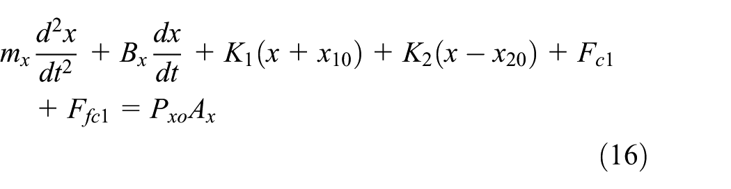
where
Equations for PC valve
The flux continuum equation of PC valve port can be written as follows

where discharge coefficient
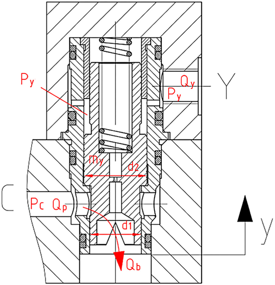
Illustration of pressure-compensated valve.
The dynamic force balance equation of the spool in PC valve can be written referring to the six-way directional valve’s as follows
where
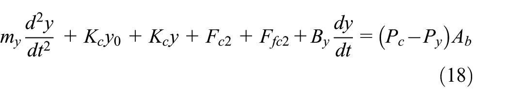
Equations for hydraulic motor
The control equations of hydraulic motor contain flux continuum equation of hydraulic motor and force balance equation of hydraulic motor. The flux continuum equations of hydraulic motor contain the inlet and outlet chamber equations (Figure 5).

Hydraulic motor.
The flux continuum equations of hydraulic motor of inlet chamber can be written as follows
The flux continuum equations of hydraulic motor of outlet chamber can be written as follows

where
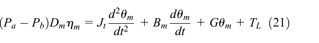
The force balance equation of hydraulic motor can be written as follows
The flow equation of hydraulic motor can be written as follows

where
The relationship between angular velocity and rotation speed of hydraulic motor can be written as follows
The relationship between angular and its velocity can be written as follows

Computation by Simulink
The model of six-way directional valve controls hydraulic motor is established to analyze the change of flow and pressure in hydraulic motor during the whole displacement range of the main spool. So the classical control theory is not suitable for this model. This article chooses to use the function in the software MATLAB/Simulink-Create Subsystems, 14 which can form the mathematical equations of each element to a subsystem. 15 Parameters can be set through the Mask Subsystems Function; thus, there is no need to open each module to modify the parameters. It makes the model easy to revise and debug.
Table 1 shows parameters that are needed to simulate the system.
Main parameters.

Figure 6 shows Simulink simulation model of SVRLF control system. The simulation system mainly contains seven subsystems, which are as follows: subsystem (1), DV displacement according to equation (16); subsystem (2), system pressure according to equations (12) and (14); subsystem (3), oil inlet according to equation (13); subsystem (4), CV displacement according to equation (18); subsystem (5), CV oil according to equation (17); subsystem (6), hydraulic motor according to equations (19)–(24); and subsystem (7) is a shuttle valve, which can choose the higher pressure between P1 and P2.

Simulink model of SVRLF control system.
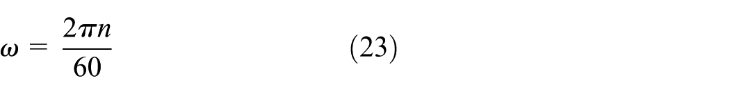
To get the simulation results, this article did the slow opening and slow closing test and the fast opening and fast closing test. In the slow opening and slow closing test, the pilot pressure is set as follows: rising from 0 to 25 bar in 50 s, maintaining for 15 s, and then reducing to 0 bar in 50 s. The pressure and flow rate curves can be obtained as shown in Figure 7. The flow rate of motor rises almost linearly when the pilot pressure increases linearly. So does the motor pressure drop. In the fast opening and fast closing dynamic test, the pilot pressure is set as follows: rising from 0 to 25 bar in 2 s, maintaining for 22 s, and then reducing to 0 bar in 2 s. The simulation curves, as shown in Figures 7 and 8, are in fairly good agreement with the test-bench results of a common slewing control valve, so they can prove the validity of simulation model.
Comparison between SVRLF simulation result and typical slewing valve test-bench result (open and close within 50 s): (a) flow rate curves and (b) pressure curves.

Comparison between SVRLF simulation result and typical slewing valve test-bench result (open within 2 s): (a) flow rate curves and (b) pressure curves.
Optimization of SVRLF
In the dynamic test, the moment of inertia of the slewing control system is so large that leads to pressure peak of the MVP reaches up to 8 MPa when the system begins to start as shown in Figure 8. The motor pressure drop and the motor flow rate fluctuate seriously at the beginning. As is known, the fluctuation of motor flow rate means that the slewing speed is not stable at the same time. It is very dangerous in practical application when an automobile crane works with load. The weights may strongly shake and then cause serious damage to crane’s jib structure. In short, the dynamic performance of the slewing valve is not good. Usually a relief valve is installed on the entrance of hydraulic motor. It can decrease the pressure peak, but the flow will overflow at the same time. So it is necessary to seek a balance between fast and stability. Dynamic design of SVRLF should be done to make the SVRLF have a better performance.
The fast start of SVRLF is related to the structure of six-way directional valve and the buffering valve. The parameters of the six-way directional valve structure contain underlap of the inlet port according to zero displacement, the initial force of spring, the spring stiffness, and the structure of throttles. The parameters of buffering valve contain cracking pressure and the amount of overflow.
Table 2 shows the dynamic parameters of the SVRLF that are need to be designed.
Dynamic design parameters.

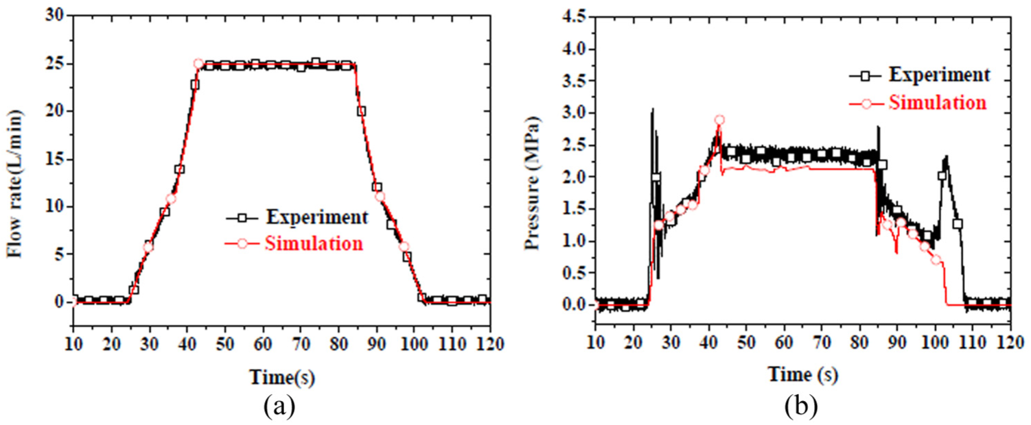
We can get the influence of underlap of the inlet port of the MVP according to zero displacement on the starting and stopping. The value is set as –1.4, –1.8, and –2.2 mm. Figure 9 shows the starting position advances as the underlap increases, but the stopping position delays, so does the spring stiffness shown in Figure 10. Therefore, it is unwise to seek the fast starting to increase the underlap and stiffness. So we choose the middle one: underlap is set to –1.8 mm and stiffness is set to 110 N/mm.

Dynamic response of different underlap for meter-in port of the MVP: (a) opening flow rate curves and (b) closing flow rate curves.
Dynamic response of different spring stiffness for meter-in port of the MVP: (a) opening flow rate curves and (b) closing flow rate curves.
There are two U-shape throttles paralleled at the BP of SVRLF. Their depth is 4.5 mm; length is 4.2 mm; radius is 2 and 4 mm, respectively; and the number in circle is 2 mm. There are three ways which can reduce the crossing area of the BP. The first one is to change the depth only. Its influence on the crossing is small, so it cannot obviously change the flow rate in a small opening of the main spool. The second way is to change the number of throttles. We choose to get rid of the U throttle of four radii. Figure 11 shows it can increase the starting position and maintain the position of stopping. The third way is to change the U-shape throttle radius to a K-shape throttle with the same parameters. However, the simulation results show that it cannot obviously change the positions in starting and stopping. So we choose to adopt the second way, changing the number of throttles as mentioned above.

Dynamic response of different throttle types for inlet port: (a) opening flow rate curves and (b) closing flow rate curves.
The optimization design of the new valve is reducing flow area of the BP (Figure 12). It can increase the motor flow rate in the small opening and make the hydraulic motor start fast. The underlap of outlet port of the MVP is negative which can avoid the flow rate rebound.

Orifice flow area curves for notches.
The relief valve can reduce the pressure peak when then crane starts and works fast with load. But it leads to large overflow and slow down the starting speed of crane upper part. So a cushioning damp and a buffering shutoff valve are added to limit overflow in the optimization design, as shown in Figure 13. The pilot control oil of buffering shutoff valve comes from the motor working port. The pilot pressure is reduced by a thread damping or annular damping to control the motion of buffering shutoff valve. The pilot relief valve is used to sense the load pressure and determine the opening and closing of the buffering circuit. There are two kinds of working states of the buffering circuit, steady heavy load, and transient pressure impact. The buffering shutoff valve works at its left or right position to cutoff the buffering circuit when the crane works with steady heavy load. The relief valve will open when the transient pressure impact is more than its set pressure, but the buffering circuit does not work due to the existence of the pilot damping which makes the action of buffering shutoff valve lag behind.

Schematic diagram of optimized SVRLF.
Verification test of SVRLF
Prototype development
As shown in Figure 14, the three-dimensional structure diagram of SVRLF is illustrated. The main parts of SVRLF are safety valve, six-way directional valve, shuttle valve, and PC valve.
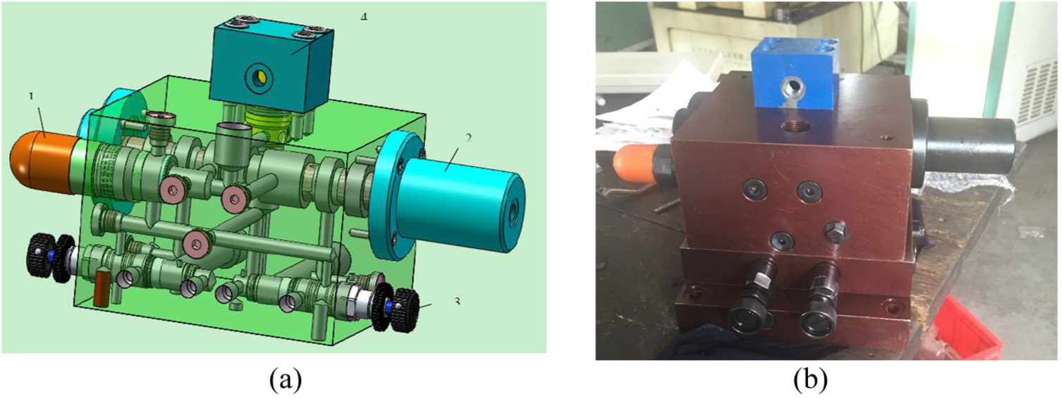
Prototype development of SVRLF. (a) Three-dimensional structure diagram and (b) prototype.
Test on a test-bench
The test-bench test of new SVRLF was done in the lab at the rotary test-bench. Figure 15 shows the hydraulic principle diagram of the rotary test-bench system. The circuits contain two parts, which are the main circuit and the pilot circuit. The main circuit provides hydraulic power for the whole system. The pilot circuit provides pilot control oil for the pilot-operated directional control valve. According to the function classification, the rotary test-bench system is made up of five parts.

Rotary test-bench of the SVRLF. (a) Hydraulic principle diagram: 1. hydraulic pump; 2. speed-regulating valve; 3. safety valve; 4. SVRLF; 5. hydraulic motor; 6. moment of inertia load module; 7. loading pump; 8. directional valve; 9. overflow valve; 10. slippage pump; 11. pilot pump; 12. electromagnetic relief valve; 13. three-way reducing valve; 14. magnetic exchange valve; 15. pressure sensor; 16. flowmeter; and 17. pressure gauge and (b) test-bench: 1. SVRLF; 2. speed-regulating valve; 3. safety valve; 4. pressure sensor; 5. flowmeter; 6. moment of inertia load module; and 7. loading pump.
The first part is pumping source, containing hydraulic pump (1) from Kawasaki company, model K3V112DT; slippage pump (10) and pilot pump (11) from Bosch Rexroth company, model A10VS0. It provides the hydraulic power that is needed to the system.
The second part is rotary part, including the SVRLF which is to test, and a hydraulic motor, swashplate-type axial piston motor XM-F40.
The third part is pilot control part. A three-way reducing valve (13) is used to provide 0–2.5 MPa pressure for the pilot hydraulic circuit of SVRLF, and magnetic exchange valve (14) is used to control a certain way of the pilot circuit.
The fourth part is loading part. It contains torque loading and inertia loading. The torque loading part uses a pump to drive a hydraulic motor. Hydraulic motor (5) and loading pump (7) are connected coaxially. The differential pressure of hydraulic motor is adjusted by an overflow valve (9). The inertia loading part adopts the combination of two large flywheels and six small flywheels, the moment of inertia range is 0–30,000 kg m2
The last part is the data sampling section, including pressure sensor (15), flowmeter (16), and data acquisition card. The model of data acquisition card is PCI-1710/1710HG from YanHua company. Data acquisition program was written by LabVIEW.
Results of slow opening and closing test
In the slow opening and closing test, the pilot pressure is set as follows: rising from 0 to 25 bar in 50 s, maintaining for 15 s, and then reducing to 0 bar in 50 s. Its purpose is to observe the valve’s linearity and adjustable area. The test result is shown in Figure 16. Compared with the common slewing control valve, the SVRLF valve has a longer adjustable area and a shorter dead zone.
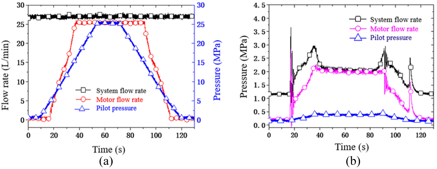
Test result of dynamic test on the test-bench: (a) flow rate curves and (b) pressure curves.
With the reduction of oil inlet’s negative valve opening of the SVRLF, the valve opening dead zone and the opening pressure of the SVRLF can be reduced. The SVRLF has a smaller flow area in the BP. The advantage of this design is that the smaller valve opening can increase the flow rate in the oil inlet, which increases the displacement of the rotary part and reduces lag.
Results of fast opening and closing test and opening dead zone test
Test of fast opening and fast closing of the SVRLF was done. The pilot pressure is set as follows: rising from 0 to 25 bar in 2 s, maintaining for 22 s, and then reducing to 0 bar in 2 s. The test result is shown in Figure 17. As shown in Figure 17, we can know that the opening time delay of SVRLF is very short and the closing time delay is about 1 s. The system’s peak pressure is about 9 MPa, and the back pressure is about 0.9 MPa when the valve is closing.
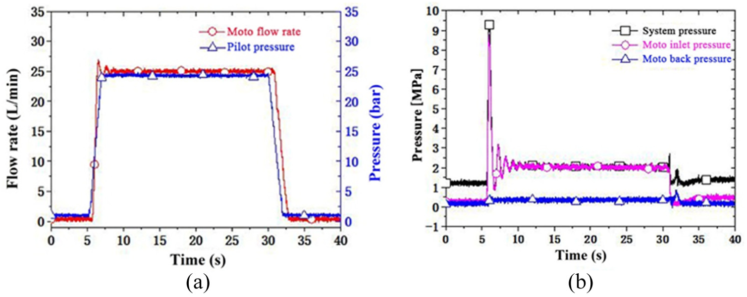
Test result of dynamic test on the test-bench: (a) flow rate curves and (b) pressure curves.
Opening dead zone test
In the test, the SVRLF and a common slewing valve were tested in the test-bench. Both valves opened and closed in 50 s. The flow rate dead zone curves are shown in Figure 18. From Figure 18(a) and (b), we can get the opening time delay of the SVRLF between flow rate and pilot pressure is about 0.4 s and the common slewing valve’s is about 0.55 s (the valve opening of the two inlets of the MVP while valves are in center position are same). When the valve is working under a small valve opening, the flow rate slope of the SVRLF is obviously bigger than the common one’s. So we can tell that the starting characteristics of the SVRLF are better. From Figure 18(c) and (d), we can see that both valves have the closing time delay between flow rate and pilot pressure. The SVRLF’s delay time is about 1.1 s and the common one’s is about 1.45 s. So we can tell that the closing characteristics of the SVRLF are better.

Flow rate dead zone comparison between SVRLF and common slewing valve. (a) Opening time delay of SVRLF, (b) opening time delay of common slewing valve, (c) closing time delay of SVRLF, and (d) closing time delay of common slewing valve.
Results of resistance to load fluctuation test
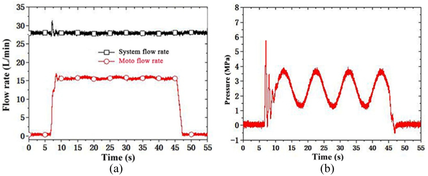
The SVRLF is paralleled with a pressure-compensation valve, which can make the flow rate of the hydraulic motor independent of the load fluctuation. To verify that, this article controlled the sinusoidal load changes and set the pilot pressure as 7 and 12 bar to test the flow characteristic in the small valve opening and medium valve opening.
As shown in Figure 19, when the SVRLF is working at a small valve opening, the load is in a sinusoidal variation between 1 and 3 MPa, but the flow rate of the hydraulic motor is constant 7 L/min, the SVRLF has a good characteristic of flow stability. It is same when the SVRLF is working at medium valve opening as shown in Figure 20.

Resistance to load fluctuation test at a small valve opening: (a) flow rate curves and (b) pressure curves.
Resistance to load fluctuation test at a middle valve opening: (a) flow rate curves and (b) pressure curves.
Table 3 shows the comparison between SVRLF and common slewing valve. Form Table 3, we can get that the SVRLF has a better performance than a common slewing valve. Both the time delay of opening and closing is lesser than a common slewing valve.
Comparison between SVRLF and common slewing valve.
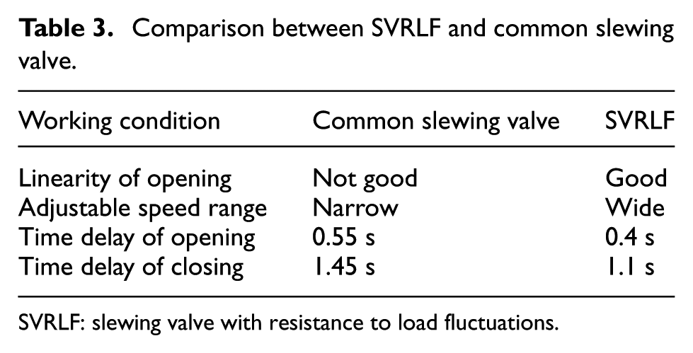
SVRLF: slewing valve with resistance to load fluctuations.
Test on a crane
The vehicle test of new SVRLF was done in ZMC85 automobile crane, as shown in Figure 21. The measurement conditions include with load 0t (none load), load 15t, and load 50t. The load pressure will fluctuate when the crane works with load.
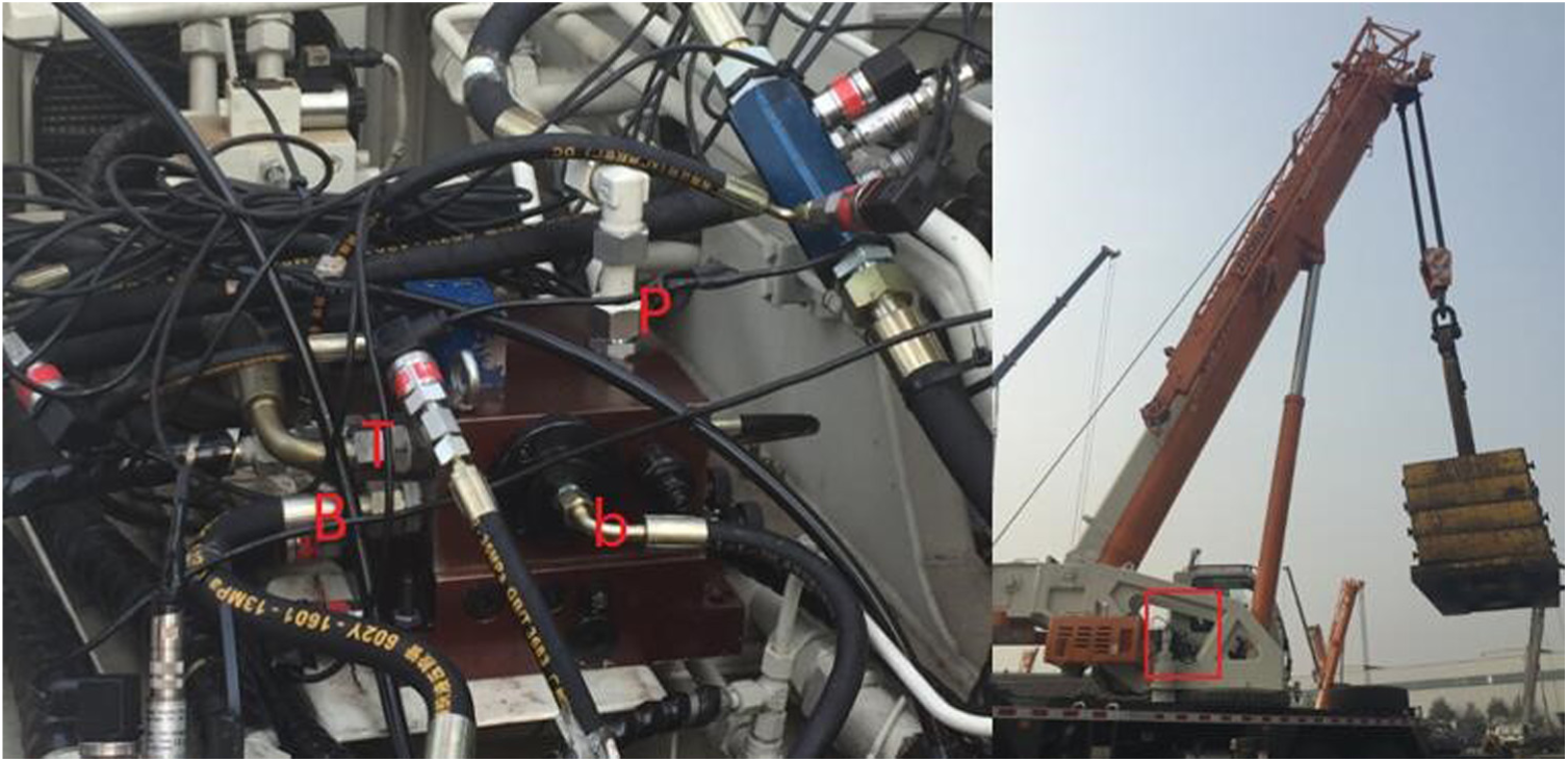
Test on the crane.
Figure 22 shows the flow rate remains constant about 9 L/min though the load pressure fluctuates between 3 and 7 MPa. It verifies that the flow rate of SVRLF is independent of load pressure.

SVRLF valve test curve in the condition of middle opening and with load 50t: (a) pressure curves and (b) flow rate curves.
A typical slewing valve test was also done in the same crane. The test results of the SVRLF and the typical slewing valve are shown in Figure 23. The test results shows that the flow rate of the SVRLF rises rapidly but the typical slewing valve lags behind its pilot pressure. It happens in the valve closing too. It suggests that the SVRLF has a good linearity of opening and wide adjustable speed range. Time delay of opening and closing of the SVRLF is 0.5 and 1.2 s, while time delay of opening and closing of the typical slewing valve is 0.7 and 1.6 s. It shows that the dynamic performance of SVRLF is better than the common one’s. We can barely feel the lagging of SVRLF, but obviously feel the lagging of typical slewing valve in the driver’s cab.

Crane test curve in the condition of middle opening and without load: (a) SVRLF flow rate curve and (b) typical slewing valve flow rate curve.
The overflow of SVRLF valve is less when the crane fast starts with load, therefore, which ensures the fast starting and reduces pressure peak of the crane upper part (Figure 24). The remarkable feature of the SVRLF is that it can control the overflow in its reducing pressure peak. In the stopping of SVRLF, the crane upper part can stop steadily without shaking.

SVRLF crane test curve in the condition of open and close in 2 s and with load 50t: (a) flow rate curves and (b) pressure curves.
A group of slow starting and breaking test were done on the crane to verify that with the load becomes larger, the valve opening dead zone will not have a long variation. To do such a test comparison, we did three contrast test experiments in the same working condition (medium valve opening, slow starting, and slow breaking) except for the weight load. The weight load was set as follows: 0t (none load), 15t, and 50t. Figure 25 shows the valve opening dead zone comparison with load 0t, 15t, 50t in the condition of slow starting and slow braking. Table 4 shows the specific valve opening dead zone comparison data. From the comparison figure and table, we can acquire that despite the weight load changes from 0t to 15t, then to 50t, the difference among the three valve opening dead zones are very small, which are 1.8, 1.6, and 1.9 s.

Opening dead zone comparison with load 0t, 15t, 50t in the condition of slow opening and closing: (a) weight load 0t (none load), (b) weight load 15t, and (c) weight load 50t.
Opening dead zone comparison.

Conclusion
In this article, the principle of bypass pressure-compensation is introduced in detail. By using this principle, the SVRLF is designed. Based on its interior structure, the mathematical function is established and simulation model in MTALAB/Simulink is built to analyze and optimize the parameters to improve its starting characteristics. A series of experiments were done both on a test-bench and on a crane. It suggests that by using the bypass pressure-compensation principle can keep the flow rate distribution of the MVP and BP stable for a certain spool position, which can make the output flow rate stable despite the various loads. The results in the crane tests show that with different weight loads, such as 0t (none load), 15t, and 50t, the valve opening dead zones are 1.8, 1.6, and 1.9 s. It shows that the SVRLF can keep the opening dead zone of MVP almost unchanged. The new designed SVRLF has better performance than other slewing valve.
Footnotes
Handling Editor: Anand Thite
Declaration of conflicting interests
The author(s) declared no potential conflicts of interest with respect to the research, authorship, and/or publication of this article.
Funding
The author(s) disclosed receipt of the following financial support for the research, authorship, and/or publication of this article: This investigation is supported by the National Natural Science Foundation of China (No. 51275451 and No. 51575476), Science Fund for Creative Research Groups of National Natural Science Foundation of China (No. 51221004), Major State Basic Research Development Program of China (973 Program) (No. 2013CB035400), and Fundamental Research Funds for the Central Universities of China (2014FZA4005).