
Abstract
Buckling analysis of nonlocal magneto-electro-elastic nano-plate is investigated based on the higher-order shear deformation theory. The in-plane magnetic and electric fields can be ignored for magneto-electro-elastic nano-plates. According to magneto-electric boundary condition and Maxwell equation, the variation of magnetic and electric potentials along the thickness direction of the magneto-electro-elastic plate is determined. To reformulate the elastic theory of magneto-electro-elastic nano-plate, the nonlocal differential constitutive relations of Eringen is applied. Using the variational principle, the governing equations of the nonlocal theory are derived. The relations between local and nonlocal theories are studied by numerical results. Also, the effects of nonlocal parameters, in-plane load directions, and aspect ratio on buckling response are investigated. Numerical results show the effects of the electric and magnetic potentials. These numerical results can be useful in the design and analysis of advanced structures constructed from magneto-electro-elastic materials.
Keywords
Introduction
In recent years, the study of smart or intelligent materials involving piezoelectric and/or piezomagnetic material structures has attracted many researchers. Smart or intelligent materials have the ability of converting energy among the electric, magnetic, and elastic energies. 1 In addition, composites made of piezomagnetic/piezoelectric materials show a magnetoelectric effect that is not present in single-phase piezomagnetic or piezoelectric materials. 2 Duo to magnetoelectric coupling effects, magneto-electro-elastic (MEE) materials have been widely used in many engineering applications, including the sensor and actuator, robotics, structural health monitoring, vibration control, and medical instruments. For the static deformation of the multilayered MEE plate, the exact closed-form solution is studied by Pan. 3 Some numerical examples in Pan 3 clearly indicate that MEE material possesses special features that may be useful in the design and analysis of smart structures. Also, Pan and Heyliger 4 proposed the free vibrations of multilayered MEE plates. Wang et al. 5 presented the analytical solution for a three-dimensional (3D) transversely isotropic multilayered MEE simply supported circular plate. Xue et al. 6 investigated nonlinear large-deflection model for MEE rectangular plate using the Kirchhoff plate theory. The large deflections of the MEE plate using the meshless local Petrov–Galerkin (MLPG) method is presented by Sladek et al. 7 Li 8 studied the buckling analysis of MEE plate on elastic foundation. An analytical investigation on buckling and free vibration behavior of Mindlin rectangular MEE nano-plates resting on Pasternak medium via nonlocal elasticity theory has been carried out by Li et al. 9 They showed that the normalized frequency of system decreases by increasing the value of electric potential. However, the normalized frequency of the system increases by increasing the value of magnetic potential. Buckling behavior of multilayered MEE plate was investigated by Kiran and Kattimani. 10 They employed the first-order shear deformation theory and derived the finite element formulation. The analysis of free vibration and biaxial buckling of double-MEE nano-plate-systems subjected to initial external magnetic and electric potentials using nonlocal plate theory was studied by Jamalpoor et al. 11 They supposed that the two nano-plates are bonded with each other using a visco-Pasternak medium. For the analysis of micro- and nano-structures, couple stress theory, modified couple stress theory, and nonlocal elastic theory were used. Buckling analysis of orthotropic protein microtubules under axial and radial compression based on couple stress theory was researched by Beni et al. 12 Jung et al. 13 presented a modified couple stress theory for buckling analysis of sigmoid functionally graded material (S-FGM) nano-plates embedded in Pasternak elastic medium. The nonlocal elastic theory was used in Jung and Han. 14
From the literature listed above and to the best of authors’ knowledge, however, the buckling analysis under varied aspect ratio of MEE nano-plate on two directions of in-plane load has not been studied. The other buckling studies of MEE plates were confined to x-direction buckling studies. The y-direction buckling studies were limited. Generally, there was no study on the variation of the buckling load in the y-direction due to the change of the aspect ratio and the nonlocal parameters. The in-plane magnetic and electric fields can be ignored for MEE nano-plates. According to magneto-electric boundary condition and Maxwell equation, the variation of magnetic and electric potentials along the thickness direction of the MEE plate is determined. A variational formulation is applied to derive the governing equations of motion and electric, magnetic distribution along the thickness direction of plate by Hamilton principle. In this study, the buckling analysis of a MEE higher-order shear deformable nano-plate is presented in both tabular and graphical forms to investigate the influences of the various parameters. The influences of various aspect ratios, electric and magnetic potentials, and in-plane load directions on the buckling response of MEE nano-plate are investigated. The buckling response obtained by the present method is compared with the results in open literature and a good agreement is acquired.
Higher-order shear deformation theory
The different shape functions
Different shape functions.

The displacements of a material point located at (
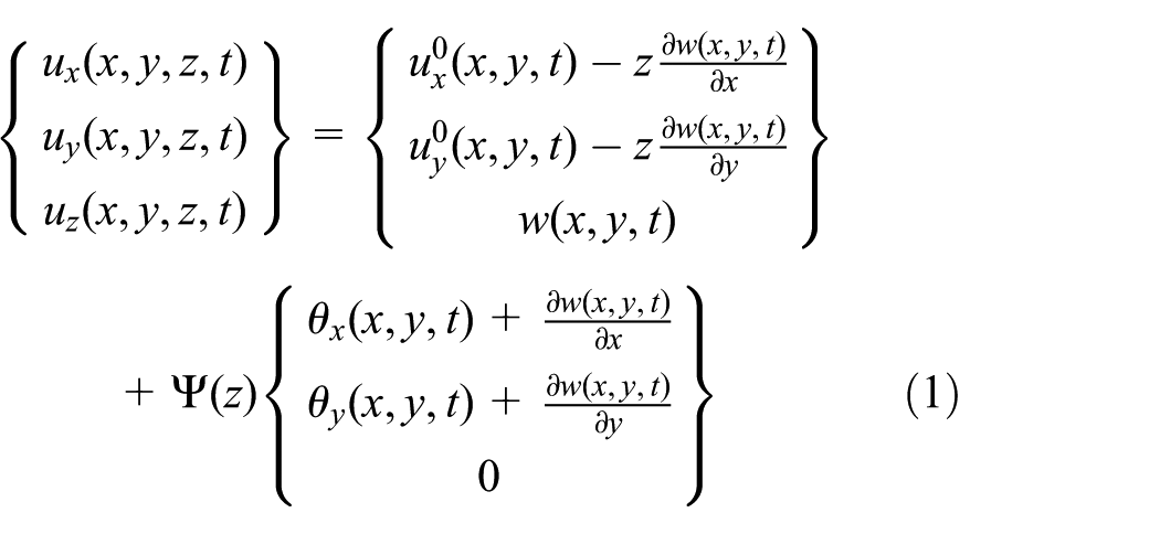
in which
The components of strain tensor, curvature tensor, and rotation vector associated with the displacement field in equation (1) are obtained as

Modeling of the MEE nano-plates
MEE equations
We consider a 3D problem such that all the field variables are functions of the coordinates
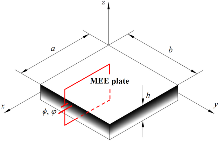
Geometry of the MEE plate.
Denote the symbols
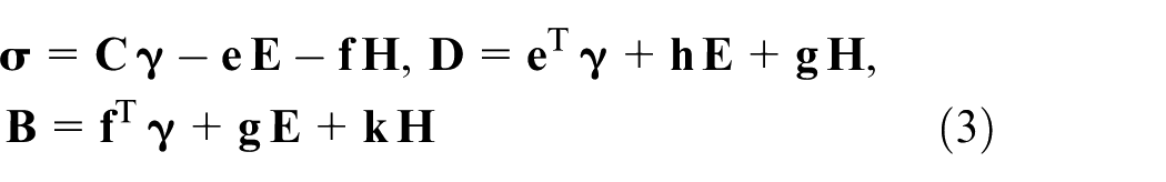
where
These vectors are defined by

For a MEE medium whose poling direction coincides with the positive z-axis, the material constant matrices

Assuming the absence of the electric charge, body force, and current densities, the equations of motion can be obtained as

with
Derivation of the governing equations
For the MEE plate, the governing differential equations of motion are derived using Hamilton’s principle which is given as

where
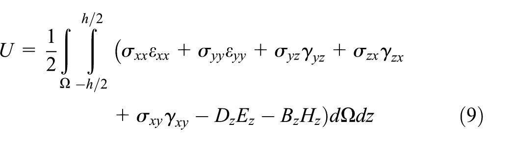
The strain energy of the MEE plate can be expressed as

Since the MEE plate is thin, the in-plane electric and magnetic field can be deleted, that is,
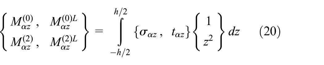
Next, we introduce the thickness-integrated stress resultants as

The kinetic energy of the MEE plate can be described as follows

The external work due to transverse loads can be written as

The potential energy due to in-plane loading is given by
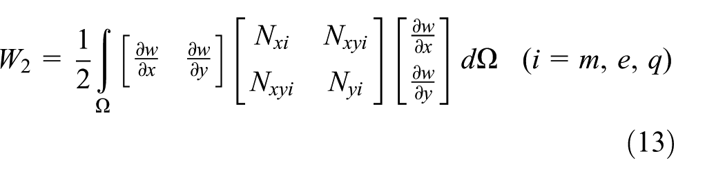


in which
Nonlocal elastic theory
The stress at a point depends only on the strain at that point in classical local elasticity theories. While in nonlocal elasticity theories, it is assumed that the stress at a point depends on the strains at all the points of the continuum. In other words, according to this nonlocal theory, strain at a point depends on both stress and spatial derivatives of the stress at that point. The nonlocal constitutive behavior of a Hookean solid (Eringen23,24) is expressed by the following differential constitutive relation

where

in which
The relations between stress resultants in local and nonlocal theory are determined by integrating equation (16) through the plate thickness

where

where
In general, differential operator ∇ in equation (16) is the 3D Laplace operator. For 2D problems, the operator ∇ may be reduced to 2D one. Thus, the linear differential operator

It is clear that the operator
Finally, using Hamilton’s principles (equation (7)) lead to the following governing equations


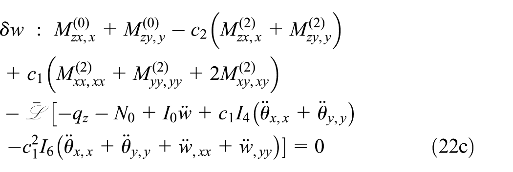

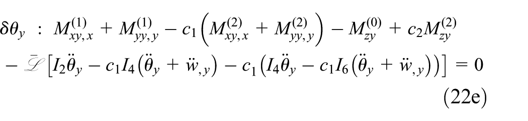


where

in which
Substituting equation (4) into equations (22f) and (22g), the two algebraic equations can be written as


By adopting Crammer’s rule, one can be obtained as
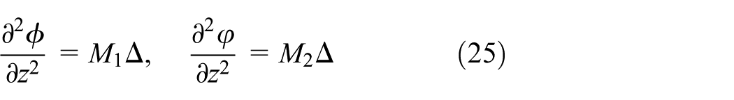
where

It can be derived from equations (25) and (26) that

and

where the electric and magnetic boundary conditions are determined as
Buckling results of nonlocal third-order shear deformation theory
Here, analytical solutions for buckling response of simply supported MEE nano-plates are investigated using the nonlocal third-order shear deformation theory to illustrate the magnetoelectric effects on buckling loads. In the case of simply supported boundary conditions, the Navier solution can be easily obtained. According to the Navier method, the displacements at the middle surface of the plane (

where
For the simply supported MEE nano-plate, we have the following boundary conditions


By substituting equation (29) into equations (22a)–(22e), we obtain the following matrix form
where

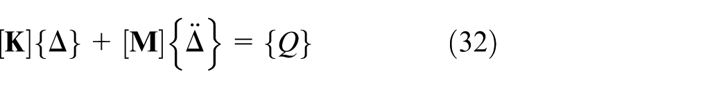
For static bending analysis, equation (32) takes
For buckling analysis, the matrix form is as follows

where
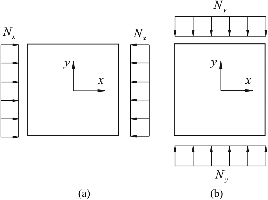
Loading conditions of FGM nano-plate for uniaxial compression (a)
Numerical results
In order to confirm the present higher-order plate theory, some convergence analyses are performed to verify the accuracy of the derived solutions and formulations against the references.
Validation
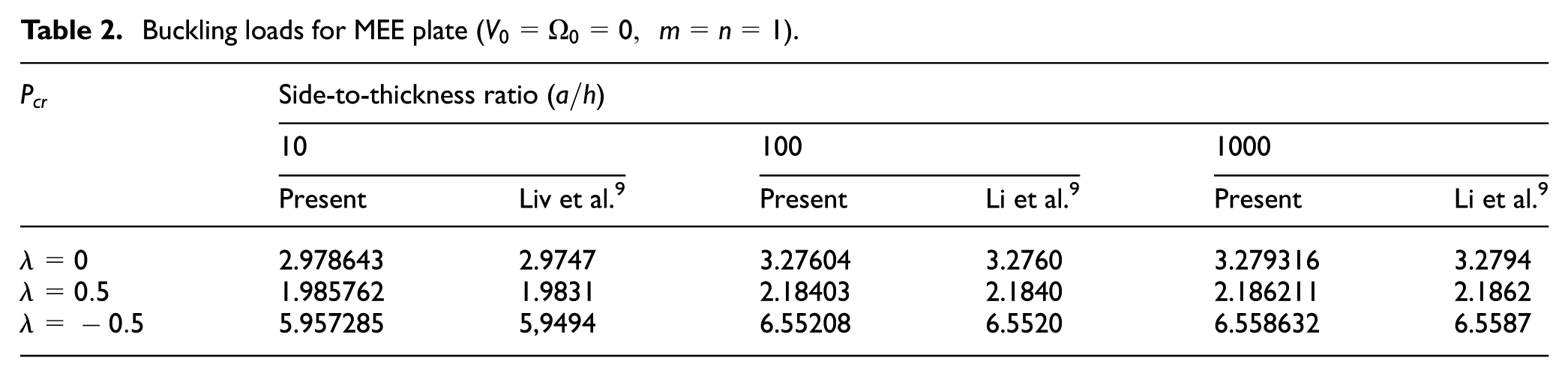
First, the buckling loads for single MEE plate are calculated and compared with the results in Li et al.
9
As shown in Table 2, the present buckling loads are in good agreement with those studied in Li et al.
9
Due to the effect of the higher-order shear deformation, in the case of side-to-thickness ratio (
Buckling loads for MEE plate (
In second analysis, as can be demonstrated in Figure 3, for MEE nano-plate, the dimensionless buckling loads calculated for various values of the nonlocal parameter from this study are compared with the results in Li et al. 9 The results of this study showed good agreement.

Variation of buckling load,
Third, the effects of electric and magnetic potential on the buckling load for MEE plate are illustrated in Figure 4. It is shown that the buckling load decreases linearly with an increase in the value of electric potential. Contrary to the type of electric potential shown in Figure 4, the buckling load increases with the increase in magnetic potential.

Variation of buckling load,
Parameter study
Parameter studies of buckling analysis for MEE nano-plate are presented. The MEE nano-plates made of BaTiO3 (piezoelectric material) as the inclusions and CoFe2O4 (piezomagnetic material) as the matrix are considered. The material properties of the MEE nano-plate are as follows: 9

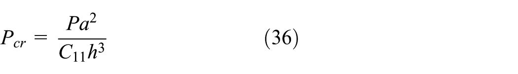
In the research of MEE nano-plate, actually, the material properties must be size-dependent and should be determined by molecular dynamic simulation or experiments. However, currently, such studies on the MEE nano-materials are lacking. Therefore, in order to understand the magneto-electro-mechanical responses of the MEE nano-plate, we choose the material properties of the macroscopic MEE materials for the case study. The length and the width of the nano-plate are a = b = 10 nm. The thickness of the nano-plate is taken as h = 1 nm. The results are presented in the nondimensional form using equation (36)
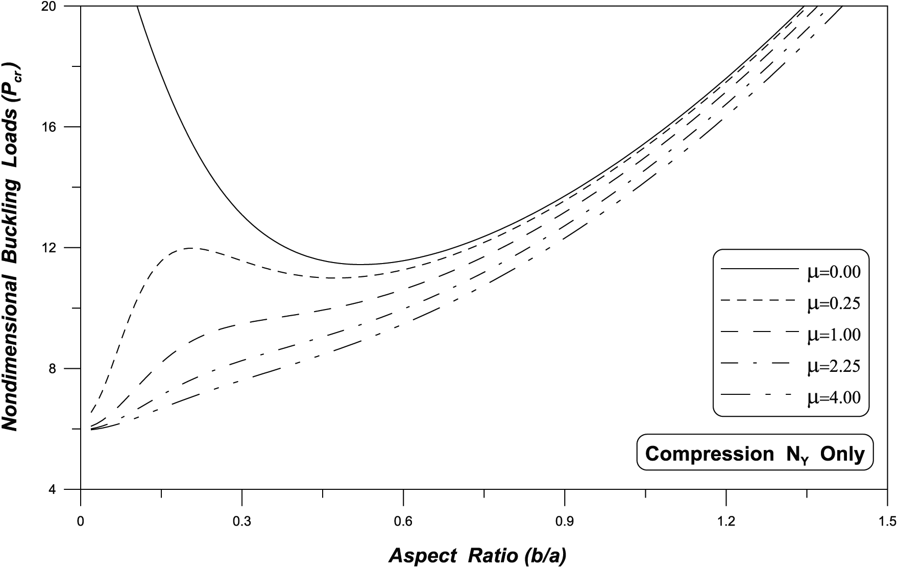
The effects of aspect ratio (b/a) on nondimensional buckling load of MEE nano-scale plate under uniaxial compression

Variation of buckling load,
Variation of buckling load,

Variation of buckling load,

Variation of buckling load,

Variation of buckling load,
To account for the effect of nonlocal parameter on responses of MEE nano-scale plate, Figure 5 plots the nondimensional buckling load with respect to the nonlocal parameter for a simply supported MEE nano-scale plate with
The buckling load for the magnetic potential
In Figure 7, buckling loads for the electrical potential
In the case of electrical potential
The effects of aspect ratio (b/a) on nondimensional buckling load of MEE nano-scale plate under uniaxial compression
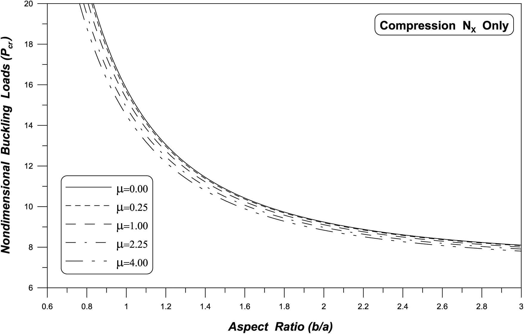
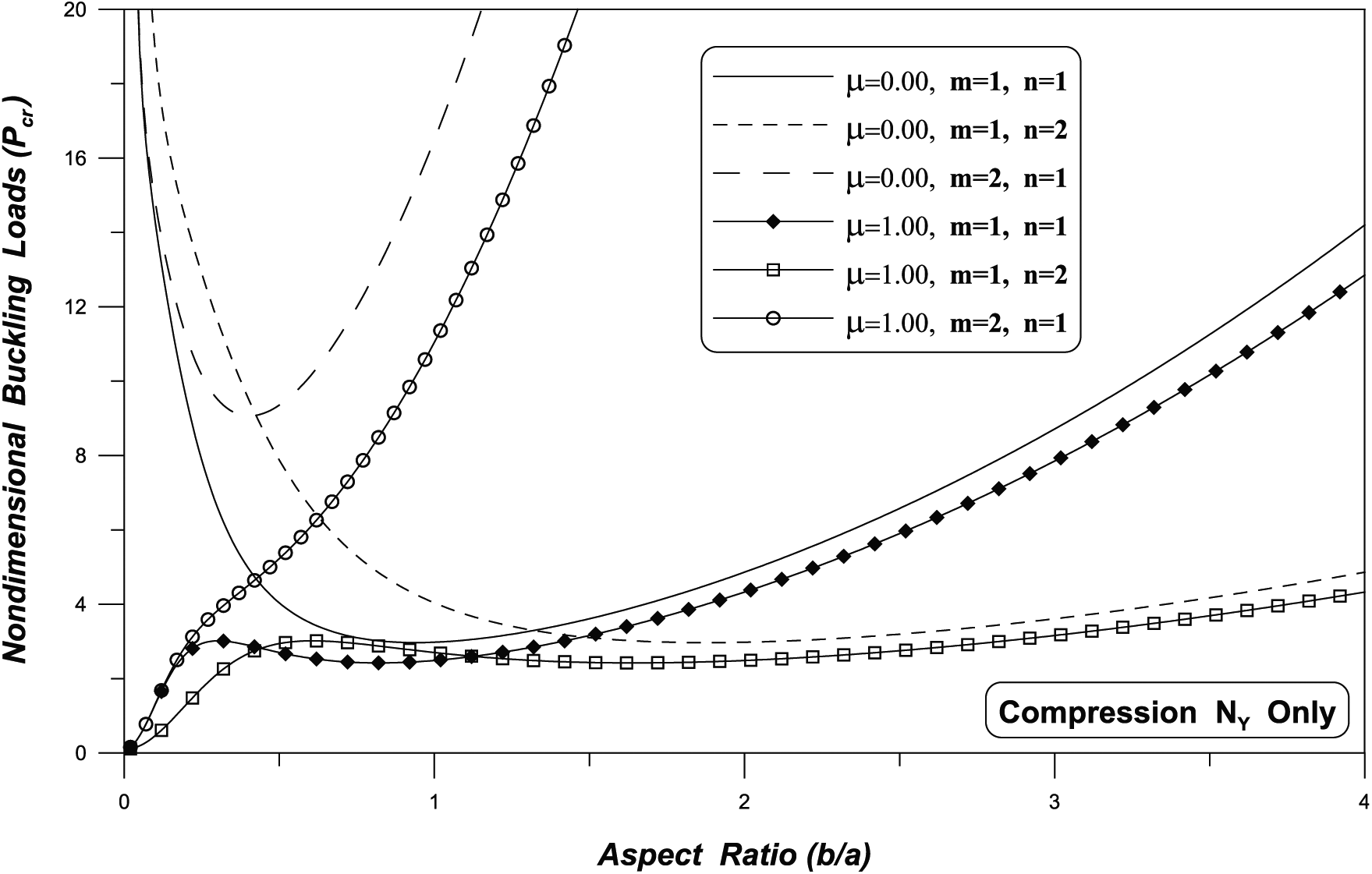
In Figure 10, the case of the MEE nano-scale plate subjected to y-directional compression, the parabolic change of the buckling load occurred when the aspect ratio was less than 1, even when the magnetic potential and electrical potential were zero. Numerical (physical) limitations of the MEE nano-scale plate could be presented according to the variation of nonlocal parameter.

Variation of buckling load,
Figure 11 shows the buckling load according to the change of buckling mode. As can be expected, when the aspect ratio is less than 1, the buckling load changes in parabolic shape are shown. When the nonlocal parameter was considered, no parabolic change was observed in the mode (m = 2, n = 1).
Variation of buckling load,
Figures 12–14 show the buckling load in consideration of magnetic potential and electrical potential. In Figure 12, the sign of the buckling load changes, which is analyzed as the effect of decreasing the stiffness by the electrical potential, as in the case of

Variation of buckling load,

Variation of buckling load,
Variation of buckling load,
For the magnetic potential
In Figure 14, the electrical potential and magnetic potential,
Figure 15 illustrates the buckling load according to the buckling mode. As in the case of

Variation of buckling load,
Conclusion
In this article, the buckling analysis of MEE nano-plate is investigated based on nonlocal theory. The in-plane magnetic and electric fields can be ignored for MEE nano-plates. According to magneto-electric boundary condition and Maxwell equation, the variation of magnetic and electric potentials along the thickness direction of the MEE plate is determined. From the numerical results, some conclusions can be drawn:
The buckling load decreases with increasing nonlocal parameter for a MEE nano-plate.
For a MEE nano-plate, the buckling load decreases linearly with electric potential, and increases with magnetic potential.
The effect of varying the aspect ratio according to the direction of the in-plane compressive load is different. Therefore, it is considered that the change of the direction and the aspect ratio of the in-plane compressive load should be considered in two directions, respectively.
The comparison of the buckling load between the case with and without the magnetic potential and the electrical potential shows the difference of the buckling load according to the buckling mode in the case of the nonlocal MEE nano-plate under Ny.
The results given in this study can be used as benchmark for buckling behavior of other nano-scale MEE plate. Furthermore, the presented theory may be extended to other cases of MEE structures such as MEE shells on elastic foundation.
Footnotes
Appendix 1
where
Handling Editor: Daxu Zhang
Declaration of conflicting interests
The author(s) declared no potential conflicts of interest with respect to the research, authorship, and/or publication of this article.
Funding
The author(s) disclosed receipt of the following financial support for the research, authorship, and/or publication of this article: This research was supported by the Basic Science Research Program through the National Research Foundation of Korea (NRF) funded by the Ministry of Education (NRF-2016R1D1A3B03931701).