
Abstract
In order to enhance automotive ride performance, permanent magnets and magnetic valves were introduced in magnetorheological dampers and hence permanent magnets and magnetic valves introduced in magnetorheological damper’s air suspension was studied. First, on the basic principle of providing magnetic field by permanent magnets and adjusting damping force by magnetic valves, a novel permanent magnets and magnetic valves introduced in magnetorheological damper was designed. On the basis of equivalent surface current model, magnetic induction intensity activated by permanent magnets in damping channel was calculated, and damping force model was built based on hydromechanics theory. Damping force–displacement experiments and damping force–velocity experiments were carried out, and the theoretical model of permanent magnets and magnetic valves introduced in magnetorheological damper was verified. Then, physical and mathematical models of 4 degree-of-freedom permanent magnets and magnetic valves introduced in magnetorheological damper air suspension model were built. In order to enhance the controlling effects of the studied air suspension, optional moving operation, moving variation operation and operation of step size changing with fluorescein proportionality were introduced into glowworm swarm optimization algorithm, and glowworm swarm optimization proportional–integral–derivative controlling algorithm was designed. Finally, three experiments with input of impact road surface, sine wave road surface, and white noise road surface were carried out, and the experimental results verified that the working performance of permanent magnets and magnetic valves introduced in magnetorheological damper air suspension based on glowworm swarm optimization proportional–integral–derivative controlling algorithm was good.
Keywords
Introduction
Automotive suspension systems, with a great impact on riding performance and handling performance, have always been one of the studying focuses, so that suspension systems have been studied from different aspects by scholars. At present, many scholars focus their research on air suspension systems. For example, Nieto et al. 1 developed an air suspension with two connecting pipes of different sizes: the riding comfort of automobiles could be improved if the shorter pipe was used, while the handling performance could be improved if the longer one was used. Eskandary et al. 2 made two rubber airbags for an air suspension. By controlling the pressure in the chambers of the two airbags, automotive ride height and stiffness can be adjusted, which could enhance automotive suspension performance. Sun et al. 3 developed a newly designed controller for an air suspension. Through the controller, the automotive height could be adjusted so that the roll and pitch angle could be regulated. Li et al. 4 established a model car test bench with interconnected air suspension, and research on the torsion elimination performance was conducted through the test bench. Abid et al. 5 investigated an air spring suspension equivalent system and optimization methods of obtaining good parameters of air spring system. Chen et al. 6 developed a height adjusting system for the air suspension of agriculture transport vehicles. With the help of designed single neuron-adaptive proportional–integral–derivative (PID) control algorithm, the adjusting system had many advantages, such as shorter response time and faster response speed. Li and Li 7 studied an effective vertical stiffness formula for air spring used by automotive air suspensions, and four experimental methods were employed to study static and quasi-static vertical stiffness. Wong et al. 8 developed a numerical model of the rolling lobe air spring, and in the model, finite element method was used. The accuracy of the numerical model was proved to be very good. Zargar et al. 9 developed a nonlinear mathematical model for air springs. Experiments were carried out to verify the model and the experimental results indicated that the model was effective. Meanwhile, many scholars focus their study on other aspects of air suspensions and have abstained fruitful academic achievements. 10
Moreover, in order to enhance suspension working performance, many scholars focus their study on magnetorheological damper (MRD) suspensions. For instance, Fakhraei et al. 11 conducted chaotic vibration analysis of an articulated vehicle with MRDs, and the analysis results could help to design heavy vehicles with MRDs. Hu et al. 12 built a quarter-car model with an MRD and designed a novel hybrid fuzzy controller for the suspension which could enhance the riding comfort of automobiles. Tang et al. 13 developed a state-observer-based Takagi–Sugeno fuzzy controller for a semi-active suspension with MRDs, and the controller was verified by a designed bench testing system. Balamurugan et al. 14 studied a novel modified algebraic model for MRDs, through which a semi-active quarter suspension model was built. Then two nested controllers with good controlling effects were studied for the suspension system. Ata and Salem 15 investigated the sky-hook, hybrid, and fuzzy-hybrid controllers for tracked vehicle with MRDs, with their advantages and disadvantages being discussed through experimental analysis. Sulaiman et al. 16 developed a semi-active controller for a light-heavy vehicle suspension with MRDs, and the controlling effect on tire force control was explored. Tyan et al. 17 built a controller for analyzing the working performance of semi-active suspension with MRDs, and through simulation experiments, the controller’s working effect was verified. At the same time, many scholars have researched MRD suspensions from other aspects. 18
Based on the literature mentioned above, a conclusion can be drawn that the working performance of automotive suspensions can be enhanced when either air springs or MRDs is used in suspensions. Meanwhile, the literature also indicates in MRD suspensions study, the suspension springs are regarded as normal ones, while in air suspensions study, the suspension dampers are regarded as normal ones. In order to enhance comprehensive performance, some scholars introduced permanent magnets into MRDs. Dong 19 investigated an MRD with permanent magnet used by automobiles, and numerical simulation results showed that automotive suspensions with the newly designed MRD had good ride comfort. Kim et al. 20 designed a new MRD, whose damping force could be tuned by the permanent magnet. Experiments were conducted, and it was demonstrated that the damping force of the proposed MRD could be tuned rapidly. Hu et al. 21 proposed a self-sensing MRD composed of permanent magnets and coils, and experimental results verified that the self-sensing MRD had good self-sensing ability and controllable damping capability. Zhang et al. 22 proposed a novel MRD with permanent magnets which could solve fail-safe problem of normal dampers. Du et al. 23 investigated an MRD with permanent magnets which could solve the problem of magnetorheological fluid sedimentation of normal MRDs. The above literature indicates that comprehensive performance can be enhanced greatly through introducing permanent magnets into MRDs. Therefore, suspensions with MRDs embedded with permanent magnets will be the developing trend of automotive suspensions. Xiao et al. 24 investigated a suspension with MRDs embedded with permanent magnets, but the suspension is traditional one with normal springs. However, the research on air suspensions with MRDs embedded with permanent magnets is rare to be seen, and there is a lot of research room. In order to enhance the working performance of air suspensions, a permanent magnets and magnetic valves introduced magnetorheological damper (PMMVMRD) was designed, and its force models were built. Then, on this basis, PMMVMRD air suspension models were built. Meanwhile, in order to enhance controlling effects of air suspensions, glowworm swarm optimization (GSO) algorithm was developed, and on this basis, glowworm swarm optimization proportional–integral–derivative (GSO-PID) controlling algorithm suitable for PMMVMRD air suspension was designed. Finally, simulations were performed for PMMVMRD air suspension based on GSO-PID controlling algorithm in three road inputs. In addition, a new type of PMMVMRD, which can be adjusted through a magnetic valve and magnetic field generated by solenoid coils and a permanent magnet, will be investigated in future. When the difference between actual damping force and desired damping force is large, adjusting method of magnetic valve can be used. When their deference is small, adjusting method of controlled magnetic field generated by solenoid coils and a permanent magnet can be used so that accurate control can be realized. If the new type of PMMVMRD can be used in air suspensions, riding comfort and handling performance can be possibly further enhanced. This article is organized as follows. In the coming five sections, mathematical models of proposed PMMVMRD are built, and its experiments are carried out as well. Next, GSO algorithm is developed, and GSO-PID controlling algorithm is designed. Subsequently, models of PMMVMRD air suspension are built. Then, simulation experiments are carried out by taking impact road surface and sine wave road surface as inputs. Finally, conclusions are drawn in the last section.
Mathematical models and experiments of PMMVMRD
Mechanic structure and working principle of PMMVMRD
By referring to MRD mechanical structure in literature 24, the piston head shown in Figure 1 is I shaped, and a circular permanent magnet (black end is N pole and white pole is S pole) is mounted in the recess. Damping channel forms between the outer surface of the piston and the inner surface of the cylinder barrel of damper. A stainless-steel resistance-magnet plate is mounted on each side of the piston so that magnetic field direction can be perpendicular to damping channel, whose magnetic field is caused only by the circular permanent magnet. There are some components in the piston head, such as a magnetic coil, a valve plug, a back spring, a screwed pipe, and magnetic valve pipes (a bigger pipe is on the right side and three symmetric circular pipes are on the left sides), which make up a magnetic valve. When no electricity is applied in the magnetic coil, magnetic valve pipe will be shut off by the back spring, while electricity is applied, the attractive force generated by the coil will overcome the elastic force to open the magnetic valve. The opening degree will be bigger with the electricity current increasing. Thus, the working principle of PMMVMRD is as follows. When electricity in the magnetic coil is 0, the valve will shut off, and all the magnetorheological liquid will flow through the damping channel, and hence strong damping force will be created. When electricity with certain strength is applied in the coil, valve will be opened to corresponding degree, some magnetorheological liquid will flow through magnetic valve, and the remaining will flow through the damping channel. Damping force will not be created by the liquid flowing through magnetic valve, but only by that through damping channel. Therefore, damping force can be adjusted through regulating the open degree of magnetic valve.

Mechanical-structure piston head of PMMVMRD.
Prediction model of damping force
According to the mechanical structure of PMMVMRD, the diagram of magnetic circuit can be achieved and shown in Figure 2, which indicates that the line of magnetic force is along the route A1→A2→A3→A4→A3→A2→A1 in a circle.

Diagram of magnetic circuit.
Suppose that total flow rate is Q in the piston movement, so equation (1) can be achieved as

where Q1 and Q2 are flow rates through magnetic valve and damping channel, respectively.
Total flow rate Q can be calculated by equation (2)

where Ap and v are the piston’s sectional area and relative velocity of piston, respectively.
Ap can be calculated by equation (3)

Suppose that the input current in the magnetic coil is I, so air-gap field strength H can be calculated through equation (4)

where N and x′ are coil turn number and moving displacement of valve plug, respectively.
Suppose that the magnetic field energy in air-gap field is E, the reduced amount dE in the air-gap field can be expressed by equation (5) according to the working principle of electromagnets
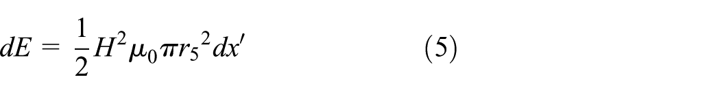
where μ0 is magnetic permeability, and r5 is the cross-sectional radius of the iron core.
According to energy conservation law, the reduced magnetic energy turns into elastic potential energy of magnetic valve. Thus, equation (6) can be achieved

where ka is spring stiffness of magnetic valve; Lv is maximum displacement of valve plug.
Equation (7) can be achieved by substituting equation (4) into equation (6)

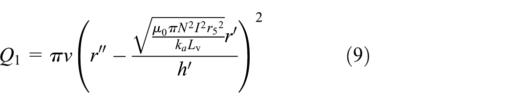
Because the right end of the valve plug is a cone, suppose that the height and radius of the cone are

Thus, according to the related theory of fluid mechanics, the flow rate Q1 can be calculated through equation (9) when the input current in the magnetic valve is I
Bingham model is employed to calculate damping force of PMMVMRD in this article. Therefore, magnetic induction intensity in damping channel must be calculated first. Magnetic induction intensity in the damping channel is only activated by permanent magnet in the studied MRD. In order to calculate the magnetic induction intensity accurately, equivalent surface current model is employed to conduct the calculation. Because the structure of permanent magnet is a hollow cylinder, rectangular coordinate system XOYZ is built by taking center and axis of cylinder as origin and Z axis, respectively. Because the cylinder is of symmetric structure about Y axis, only XOZ plane needs to be taken into consideration, and XOZ coordinate system is shown in Figure 3(a). As is shown in Figure 3(a), equivalent surface current of the permanent magnet is surface current 1, 2, 3, and 4, which can be regarded as superposition of several endless line-current elements. Suppose that any point coordinate in damping channel is P(x, y, z), then, point P(x, y, z) magnetic field activated by permanent magnet is the value that P(x, y, z) magnetic field activated by equivalent surface current 1 and 2 minus that activated by 3 and 4, according to model of equivalent surface current. Point P(x, y, z) magnetic field activated by line-current element of surface current 1 is shown in Figure 3(b). Because the permanent magnet is of symmetric structure about Y axis, make y = 0 and suppose that coordinate of any point on line-current element of surface current 1 is P(x″,y″,z″). Likewise, make y″ = 0 and point P(x, y, z) magnetic field created by the line-current element can be expressed by equation (10)
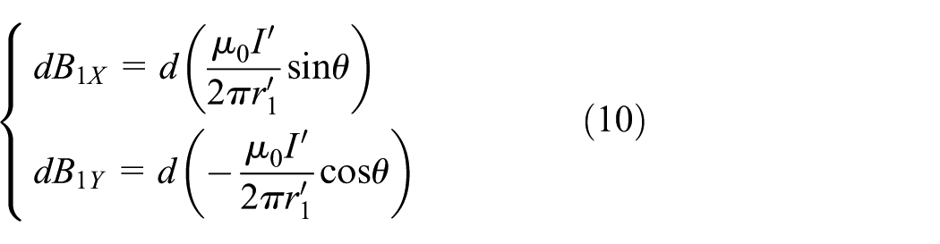
where

Diagram of permanent magnetic field: (a) diagram of permanent magnet surface current; (b) diagram of point P(x, y, z) magnetic field activated by line-current element of surface current 1.
Equation (11) can be achieved according to geometrical relationship in Figure 3(b)

Suppose that

where
Equation (13) can be achieved according to equations (11) and (12)

Equation (14) can be achieved according to geometrical relationship

In damping channel, point P(x, y, z) magnetic flux density created by surface current 1 can be calculated through equation (15)

Equation (16) can be achieved through equation (15)

Likewise, in damping channel, point P(x, y, z) magnetic induction density created by surface current 2, 3, and 4 can be calculated through equations (17)–(19)

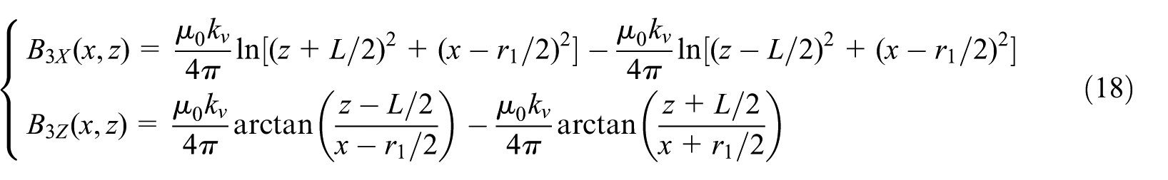

where

Critical shear yield stress

where
Damping force model of normal MRD can be achieved as follows according to Bingham model 25
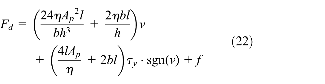
where
Equation (23) can be achieved through transforming equation (22)
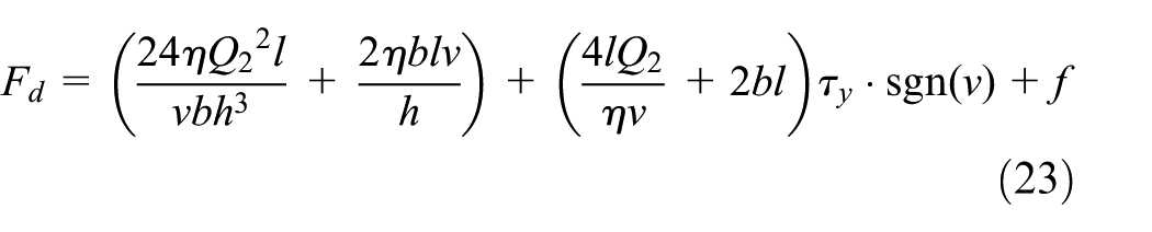
Damping force Fd can be achieved through putting the parameters of designed PMMVMRD into equation (23)

Experiments of PMMVMRD
In order to verify working performance of the studied PMMVMRD, a damper is manufactured on the basis of an automotive suspension technique requirement of Chery Automobile Co, Ltd., and the commercial magnetorheological liquid provided by Ningbo Shangon Center of Structrual Monitoring and Control Engineering Co, Ltd. The experiments on PMMVMRD are carried out through PA-20-Z 20 kN electrohydraulic servo suspension system produced by Shanghai Beiyue Machine Test CO, Ltd. In the experiments, on the basis of QCT 545-1999 (bench experiment methods of automotive telescopic shock absorbers) and by taking road excitation of coming real vehicle tests into consideration, sine wave is employed to be input signal, the maximum exciting velocity is 0.3 m/s, amplitude is 30 mm, frequency is 1.95 Hz, and input electric current is 0–1.2 A. The test rig is shown in Figure 4, and the experimental results are shown in Figures 5 and 6, in which, Figure 5(a)–(d) shows damping force–displacement curves and Figure 6 shows damping force–velocity curves when the input electric current is 0, 0.4, 0.8, and 1.2 A, respectively. Figure 5 indicates when input current in the coil is 0 A, the damping force reaches maximum, and the maximum value can be 1 kN. The reason lies in that: when input current is 0 A, the magnetic valve shuts off, and all the magnetorheological liquid flows through damping channel so that large damping force is created. When input current in the coil is 1.2 A, the damping force reaches minimum, nearly equal to 0. The reason lies in that: when the input current in the coil is 1.2 A, the magnetic valve is opened fully, the major magnetorheological liquid flows through magnetic valve and few liquid flows through damping channel so that small damping force is created. With the increase of input current in the coil, the open degree of the magnetic valve increases accordingly and so does flowing rate. Thus, liquid flowing through damping channel decreases, and the damping force decreases accordingly. The conclusion can be drawn from the above experiment analysis that damping force of the designed MRD can be adjusted through changing the input current in the magnetic coil so that PMMVMRD can meet technique requirement of automotive suspensions. Moreover, when the input electric current is 0, the PMMVMRD can output bigger damping force so that the proposed PMMVMRD can solve the fail-safe problem of normal dampers. Meanwhile, because permanent magnets are introduced into PMMVMRD, magnetorheological fluid sedimentation problem of normal MRDs can be solved with magnetic field of permanent magnets. Therefore, the proposed PMMVMRD has better working performance than normal servo-valve dampers and MRDs. It can be used not only in automobiles but also in vibration damping fields with high requirements on dampers, such as buildings and mechanic systems.

Test rig of PMMVMRD.

Damping force varying with input current at 30 mm amplitude and 1.95 Hz frequency: (a) damping force versus displacement at 0 A current; (b) damping force versus displacement at 0.4 A current; (c) damping force versus displacement at 0.8 A current; and (d) damping force versus displacement at 1.2 A current.
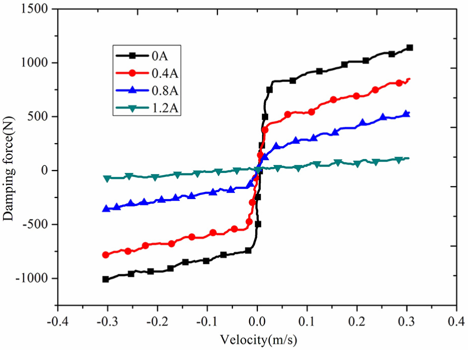
Experimental damping force versus velocity.
Figure 7 is damping force–velocity curve simulated by the designed model in this article. For the convenience of analyzing and comparing simulation results of damping force–velocity and tested results of actual MRD, characteristic physical dimensions of PMMVMRD models are similar to those of actual tested MRD. It can be indicated that simulated curves agree with those of experiments under different current and velocity. The comparison of Figures 6 and 7 shows the error between simulation and experimental results is very small. In compression travel, maximum damping force of simulations and actual experiments are 1084 and 1007 N, respectively, with the error being less than7.6%. In rebounding travel, maximum damping force of simulations and actual experiments are 1479 and 1405 N, respectively with the error being less than 5.2%. The above analysis verifies that the damping force model designed in this article is correct.
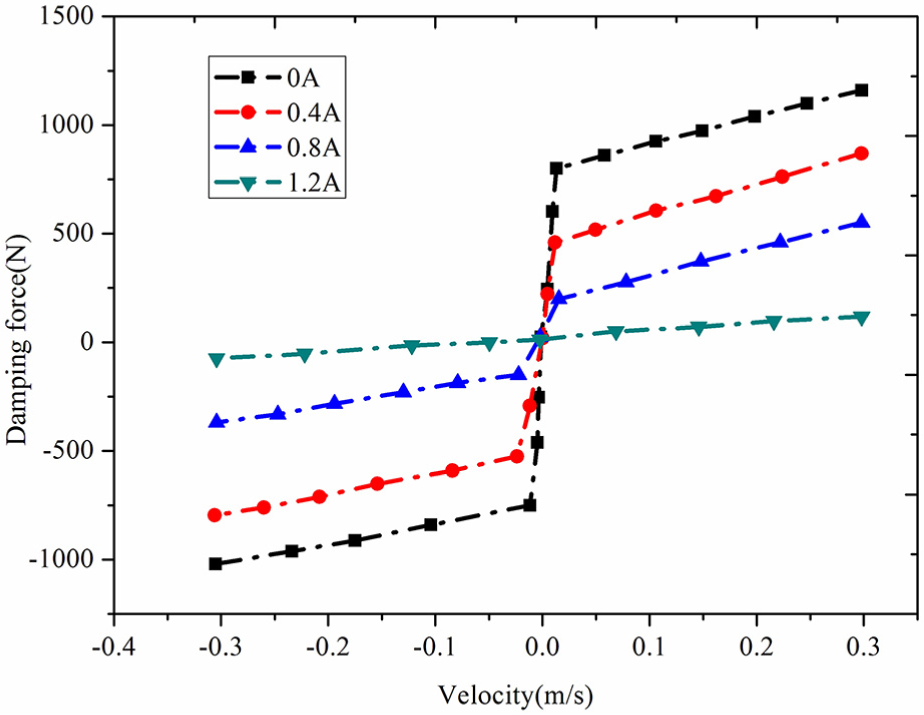
Simulated damping force versus velocity.
Design of GSO-PID
Development of GSO
PID controller has three controlling units: proportion, integration, and differentiation. The difference between desired controlling values and actual controlling values is the controller input. Design of PID controller is realized through determining proportionality factor, integration time factor, and differentiating time factor. PID controllers have many advantages, such as rapid responding speed, high controlling accuracy, and good robustness, which can enhance working performance of controlled systems greatly. However, the factors of PID controllers are difficult to determine, so the application of PID controllers is limited. GSO algorithm with many advantages such as greater searching ability and higher optimizing accuracy is a new intelligent optimization algorithm designed by Indian scholars Krishnanand and Ghose in 2005. Therefore, GSO algorithm has been used in many fields, such as assembly sequence planning, mobile robot localization, traveling salesman problems, and wavelength variable selection method in near infrared spectroscopy. It is proved that the application effects are good. If PID controllers and GSO algorithm can be combined to design GSO-PID controlling algorithm, the new controlling algorithm hopes to enhance the working performance of automotive electronic systems greatly. Thus, in order to enhance controlling performance of PMMVMRD air suspension, a novel GSO-PID algorithm is designed and employed in this article to carry out control experiments of suspension system.
The basic working theory is as follows. At the beginning, n glowworms are distributed randomly into a D-dimensional space, and every glowworm has its own fluorescein determined by its position. The better the position a glowworm has, the more the fluorescein it has and the more intensive the light it can radiate. Hence, the optimized objective value is better. Each glowworm has its own decision domain, in which glowworms select others with more fluorescein than themselves to construct neighborhoods. In the neighborhoods, each glowworm selects randomly another glowworm with higher fluorescein and move one step toward the selected one in each iteration. In the end, glowworms will stay around several positions with good objective values through continuous moving so that searching on the whole space can be completed.
Literature 26 shows that many scholars across the world have carried out deep research on GSO algorithm. It has been widely used in controlling collective robots, solving 0-1 Knapsack Problem, optimizing multi-modal functions, and detecting multi signal sources, with desirable applying effects. 27 However, nowadays, GSO algorithm still has some disadvantages, such as low optimization velocity, being easy to fall into local optimization and the like. 28 Thus, in view of the above problems, optional moving operation, moving variation operation, and operation of step size changing with fluorescein proportionality are introduced into normal GSO algorithm. Thus, a novel GSO algorithm is developed and its specific theory is as follows:
Optional moving operation. In order to avoid slow optimizing velocity, caused by blind selection of glowworms with more fluorescein to move in optimization, the following operations are conducted: order all the glowworms in neighbors by their fluorescein, select k glowworms with more fluorescein; then, select and move to a glowworm in the k glowworms randomly.
Moving variation operation. To avoid falling in local optimum, operation of moving with certain-probability variation is introduced in glowworm movement; that is, in the sixth step, select and move to jth glowworm in its neighbor and renew position according to equation (25)
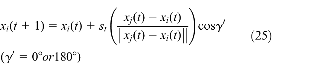
where xi and xj are ith and jth glowworm position, respectively; st is step size;

3. Operation of step size changing with fluorescein proportionality. Step size st is a constant value in the optimization of normal GSO algorithm, so good objective domain will be missed if the step size is too big, and slow velocity will be caused if the step size is too small. Therefore, in the optimization of developed GSO algorithm in this article, the operation, in which step size changes with ratio between the moving glowworm fluorescein and its selected glowworm fluorescein, is employed. More specifically, big step size is employed for big ratio, while small step size for small ratio. So st can be described by equation (27)
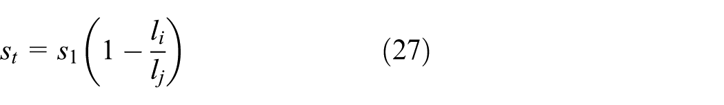
where s1 is step size parameter; li and lj are fluorescein of ith and jth glowworm.
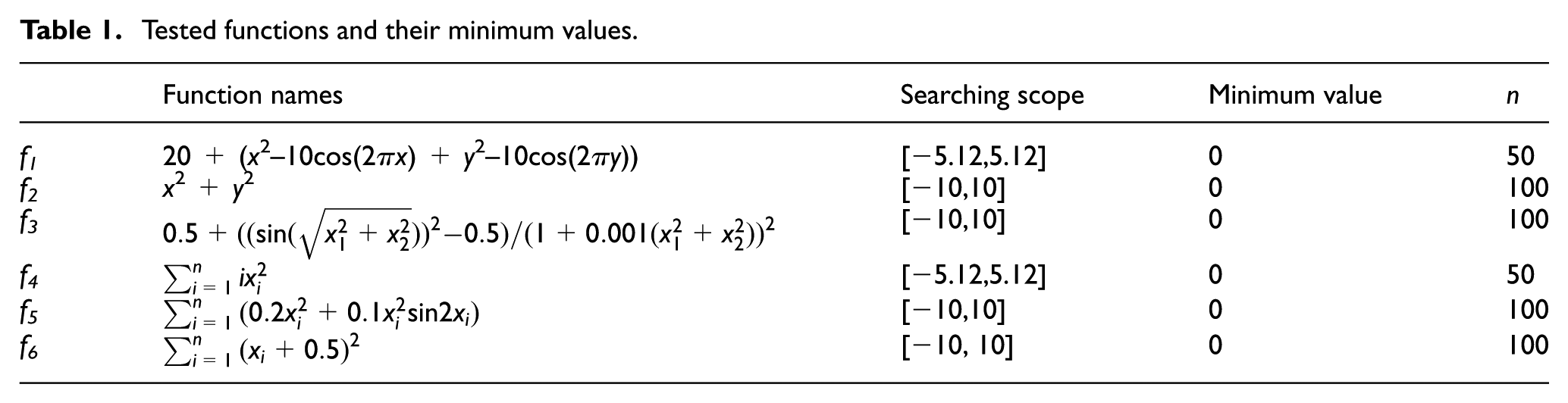
In order to verify the optimizing effect of GSO algorithm with the proposed three operations, simulation experiments are conducted by using six standard testing functions
Tested functions and their minimum values.

Algorithm comparison of optimizing f1–f6: (a) algorithm comparison of optimizing tested function f1; (b) algorithm comparison of optimizing tested function f2; (c) algorithm comparison of optimizing tested function f3; (d) algorithm comparison of optimizing tested function f4; (e) algorithm comparison of optimizing tested function f5, and (f) algorithm comparison of optimizing tested function f6.
Design of GSO-PID
In sky-hook algorithm, a damper is supposed to be mounted between inertial coordinate system and sprung weight, and its force direction is opposite to motion direction of the sprung weight. Sky-hook damper can control absolute moving velocity of sprung weight so as to enhance automotive riding comfort. At present, sky-hook algorithm is widely used in automotive suspensions. Thus, PMMVMRD is controlled by sky-hook algorithm, while air spring of semi-active suspension is controlled by GSO-PID algorithm in this article. Before determining the sky-hook factors, reasonable stiffness coefficient and dampers’ damping factors of front and rear suspensions are given by designers according to researched automobile system features. In order to enhance handling and riding performance of automobiles, transfer function HT of tire dynamic load and transfer function HS of automotive riding performance are deduced based on suspensions system models. A group of amplitude–frequency characteristic curves can be achieved through changing the value of sky-hook factors and simulations. Hence, the value of satisfying both handling and riding performance of automobiles is selected as the sky-hook factor. Thus, in the process of optimizing sky-hook factors, stiffness coefficients of suspension springs are regarded as constant value, and PID controller does not work in this process. Based on transfer functions of PMMVMRD air suspension systems, simulations are conducted by using different factors of sky-hook algorithm. Finally, the better sky-hook factors of front suspension and rear suspension are determined as 2100 Ns/m and 2300 Ns/m, respectively. In order to enhance robustness of air spring, GSO algorithm is employed to optimize three factors of PID algorithm, namely, proportionality factor kp, integration time factor ki, and differentiating time factor kd. The working principle is as follows. First, every glowworm in a group is distributed in a three-dimensional (3D) space
Meanwhile, the more shining a glowworm is, the better the position it has, which means that the glowworm has better objective value, and corresponding PID controller has better factors. In the space, every glowworm has its own visual domain, in which, every glowworm moves to the more shining one with a specified probability. Every time, the glowworm moves a step size, that is, corresponding PID controller of glowworm position moves to a better one for a step size. Finally, most of the glowworms will gather around several ones with higher fitness through the continuous movement and optimized values, that is, optimized PID controller, are found out.
In order to speed up optimization velocity of GSO algorithm and avoid local optimum, the three operations, such as optional moving operation, moving variation operation, and operation of step size changing with fluorescein proportionality, which are proposed and introduced in GSO algorithm in previous section (sections “Development of GSO” and “Design of GSO-PID”). On the basis of PMMVMRD air suspension models, the performance index J of PID controller is expressed by equation (28)

where J1, J2, J2′, J3, and J3′ are root mean square (RMS) values of acceleration of automobile mass center, front-suspension working space, rear-suspension working space, front-tire dynamic load, and rear-tire dynamic load, respectively; β1, β2, β2′, β3, and β3′ are weighted values.
The control scheme of GSO-PID is shown in Figure 9, and the working flow of the developed GSO algorithm is as follows:
Step 1: Initiate parameters.
Step 2: Distribute ith glowworm into 3D space
Step 3: Transfer corresponding objective function J(xi(t)), of xi(t) position of ith glowworm in tth iteration, into corresponding fluorescein li(t)

where
Step 4: Every glowworm selects glowworms with more fluorescein in domain within dynamic decision radius to make up its neighbor Ni(t)

where
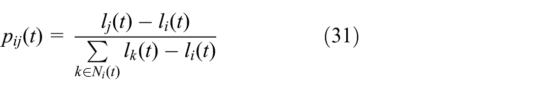
Step 5: According to “optional moving operation” proposed in sections “Development of GSO” and “Design of GSO-PID,” order all the glowworms in neighbors and select k glowworms with more fluorescein; then, calculate the probability pij(t) of ith glowworm moving to jth glowworm in its k glowworms through equation (31)
Step 6: Select jth glowworm through roulette and then move to it. Position is renewed according to equation (25). Thus, “moving variation operation” and “operation of step size changing with fluorescein proportionality” proposed in section “Development of GSO” and “Design of GSO-PID” are achieved through moving factor
Step 7: Renew radius of dynamic decision domain through equation (32)

where β is the variation ratio of neighbor, and nt is the threshold of neighbor.
Step 8: If GSO algorithm reaches maximum iteration, output three factors kp, ki, kd of PID controller represented by optimum position of the glowworm group. Otherwise, calculate dynamic decision domain
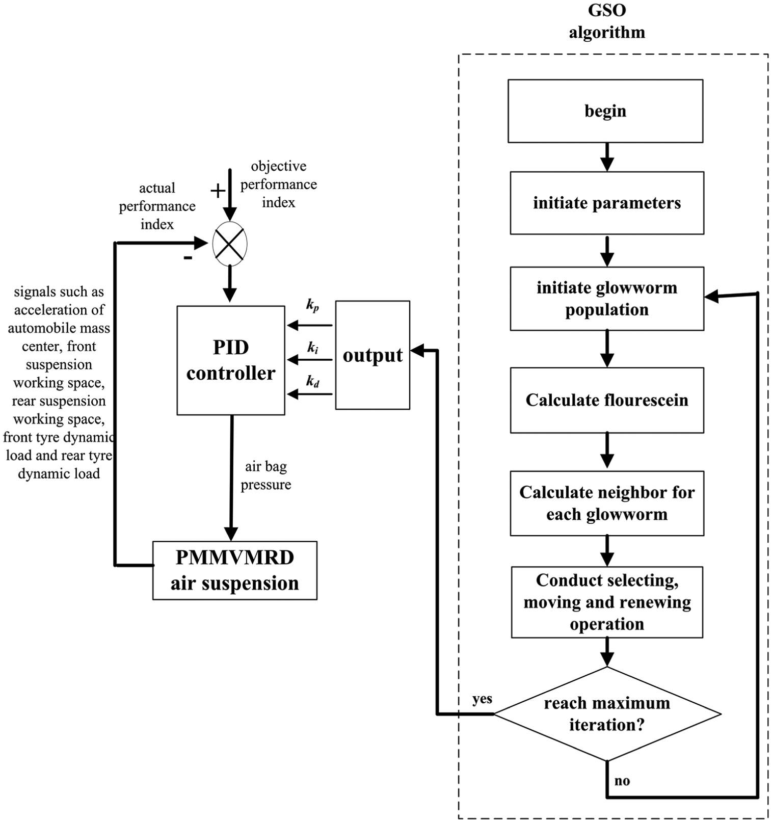
Control scheme of GSO-PID.
First, in the process of optimization simulation, specific numerical value of objective performance index is determined by the designers according to the features of controlled suspension systems and controlling requirement. Then, real-time signals, such as acceleration of automobile mass center, front-suspension working space, rear-suspension working space, front-tire dynamic load, and rear-tire dynamic load, are collected so that the RMS values of these real-time signals can be calculated. On this basis, actual performance index is calculated through equation (28). Actual performance index is the feedback of PID controllers of suspension systems, and difference between actual performance index and objective performance index is the deviation of the PID controller.
Modeling of PMMVMRD air suspension
Modeling of airbag
The structure diagram is shown in Figure 10. 30 Suppose that the pressure in the air gasbag is p and pressure atmosphere is pa, then output force Fa of air spring can be expressed by equation (33)

where Ae is effective area of airbag.
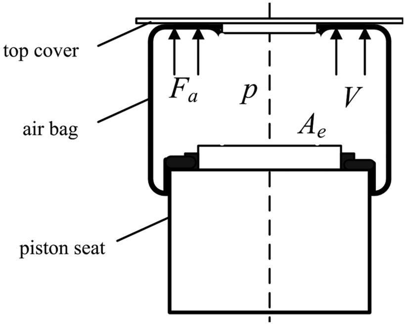
Structure diagram of airbag.
According to Hooke’s law, stiffness kb of air spring can be calculated by equation (34)

where s is the vertical displacement of air spring; in this article, s is the difference between automotive sprung mass and unsprung mass.
Air in the bag meets ideal gas state equation (35)

where ko is constant value; V is volume of airbag, n is air polytropic exponent.
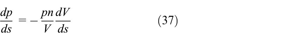
Equation (36) can be achieved through working out derivation on both sides of equation (35) about s

Equation (37) can be achieved through transforming equation (36)
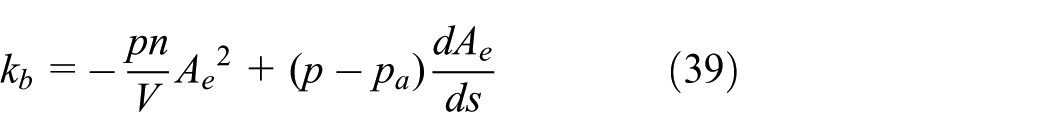
Equation (38) can be achieved according to airbag feature

Equation (39) can be achieved through putting equations (37) and (38) into equation (34)
Because the airbag is used by air suspension, equation (40) can be achieved
Therefore, stiffness of air spring can be calculated through equation (41)

Thus, elastic force of air spring can be achieved through equation (41)

Equation (43) can be achieved through equation (42)

It can be concluded that stiffness and elastic force of air spring can be adjusted through controlling the pressure in the airbag.
According to the GSO-PID control scheme shown in Figure 9, the electronic control unit (ECU) of PMMVMRD air suspension collects the signals such as automotive mass center acceleration, front-suspension working space, rear-suspension working space, front-tire dynamic load, and rear-tire dynamic load. The actual performance index is calculated based on the collected signals and compared with the target index in ECU so that pressure in the airbags is calculated by GSO-PID controllers. Inflating or outgassing for airbags are determined through comparison between the calculated and actual pressure in airbags. Finally, pressure in airbags is adjusted through controlling magnetic valves so that working performance of PMMVMRD air suspension is optimized.
Modeling of 4 degree-of-freedom suspension
The automobile with 4 degree-of-freedom is researched, and sky-hook algorithm is employed to control the PMMVMRD air suspension. First, suppose that there is a sky-hook damper on each automobile body corresponding to front and rear axis. The physical model of the PMMVMRD air suspension is shown in Figure 11. Based on the physical model, mathematical models are built.

Physical model of 4 degree-of-freedom air suspension.
Kinematic equation of automotive body can be expressed as equation (44)

where ms is the automotive sprung mass; xc is the automotive center displacement; Lx is the automotive axle base; bx is the distance from automotive mass center to front axis; Φ is the pitching angular of automobile; JΦ is the rotary inertia; Fa1, Fa2 are the elastic force of air springs of front and rear suspensions; C 1 , C2 are the dampers’ damping factors of front and rear suspensions; xt1, xt2 are the unsprung weight displacement of front and rear suspensions; xs1, xs2 are the sprung weight displacement of front and rear suspensions; kt1, kt2 are the stiffness coefficient of front and rear tires; and xr1, xr2 are the disturbance input from the road at front and rear tires.
Kinematic equation of unsprung weight is expressed as equation (45)

where mt1, mt2 are unsprung weight of front and rear suspensions.
Because sky-hook dampers are imaginary, the damping force of sky-hook force is generated by PMMVMRDs. Therefore, damping force of PMMVMRDs of front and rear air suspensions is the resultant force between sky-hook damping force and damping force generated by original damping factors, that is

where Fd1, Fd2 are the actual output force of PMMVMRDs of front and rear suspensions.
In the actual control of PMMVMRD air suspensions, signals such as xt1, xt2, xs1, and xs2 are collected by the controlling systems, and actual force of PMMVMRDs is calculated according to equation (46). Then, PMMVMRD controlling electric current of generating Fd1 and Fd2 is calculated through equation (24). Hence, the proper electric current is applied to PMMVMRDs through the controlling systems. Proper damping force is generated so that performance of PMMVMRD air suspensions can be optimized.
Simulation experiments
In order to verify the working performance of studied PMMVMRD air suspension controlled by GSO-PID algorithm, a testing automobile from Chery Automobile Co, Ltd is employed to conduct the simulation experiments, and main parameters of the testing automobile are: ms = 730 kg, Jϕ = 1230 kg m2, mt1 = 40 kg, mt2 = 36 kg, kt1 = 175 KN/m, kt2 = 175 KN/m, bx = 1 m, and Lx = 2.8 m. By referring to the method in literature 31 and in view of automotive safety, riding comfort, and handling performance comprehensively, weighted values are set as follows: β1 = 1, β2 = 2865.7, β2′ = 2865.7, β3 = 355.2, and β3 = 413.6. The simulation experiments are conducted at three working conditions, including input of impact road surface, sine wave road surface, and white noise road surface.
Simulation experiments of impact road surface
Simulation experiments of impact road surface are conducted according to Chinese Standard GB5902-86. In this simulation, the automobile passes a single bump, and the vibration of the automobile is employed to evaluate the experiments. Suppose that the driving speed of automobile is u′, then time domain expression of road pulse impact on tires can be expressed by equation (47)

where u′ is Am = 0.1 m and L′ = 5 m.
In order to investigate working performance of PMMVMRD air suspension controlled by GSO-PID algorithm, especially the effect of applying PMMVMRD in air suspension, experimental results are compared with those of normal MRD suspension controlled by GSO-PID and passive suspension. During the GSO-PID optimization, impact road surface is employed as road-induced excitation. The normal MRD is from the testing automobile, and the main parameters are as follows: inner diameter of working cylinder is 30 mm; length of damping channel is 20 mm; radius of piston is 13 mm; working gap is 1.0 mm; diameter of piston rod is 10 mm; turn number of coil is 100.
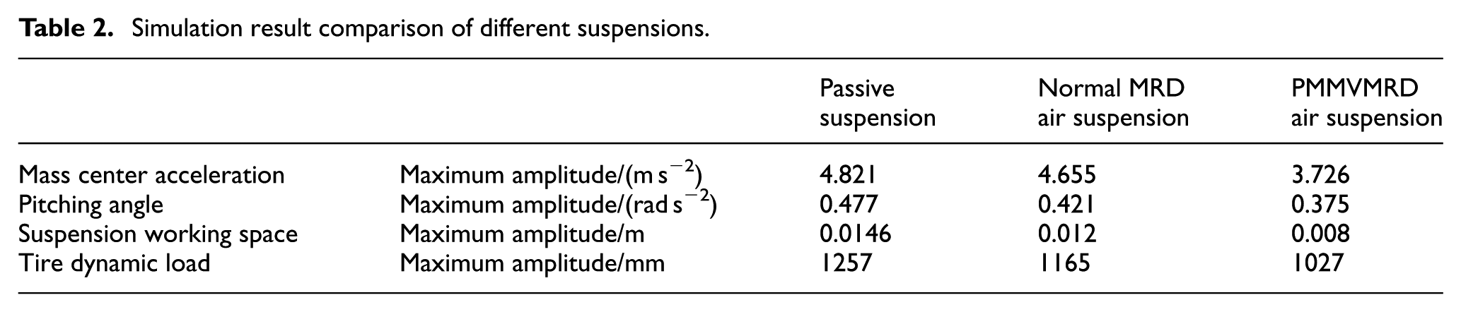
The results are shown in Figure 12(a)–(d), which indicate that peak value of mass center acceleration, body pitching angle acceleration, suspension working space and tire dynamic load of PMMVMRD air suspension controlled by GSO-PID, normal MRD air suspension controlled by GSO-PID, and passive suspension increases in sequence. Meanwhile, adjusting time of the above four values increases in sequence, too. Therefore, better control results and shorter adjusting time can be achieved by the proposed PMMVMRD air suspension. These demonstrate that both of the semi-active suspension can enhance suspension performance. PMMVMRD air suspension controlled by GSO-PID has better working performance than normal MRD air suspension controlled by GSO-PID, which indicates that the effect of applying PMMVMRD in air suspension is better than that of applying normal MRD in air suspension. In order to conduct further comparison between the two semi-active suspensions, peak values of mass center acceleration, pitching angle acceleration, suspension working space, and tire dynamic load are calculated and shown in Table 2. Table 2 indicates that compared with normal MRD air suspension, mass center acceleration, pitching angle acceleration, suspension working space, and tire dynamic load of PMMVMRD suspension controlled by GSO-PID decreases by 20%, 10.9%, 33.3%, and 11.8%, respectively. This demonstrates that riding and handling performance of PMMVMRD air suspension controlled by GSO-PID are better than those of normal MRD air suspension controlled by GSO-PID. Therefore, both quality and quantity analysis show that in the simulation experiment, PMMVMRD air suspension controlled by GSO-PID has good performance and effect of applying PMMVMRD in air suspension is good.

Time-domain simulation results of impact road surface: (a) mass center acceleration; (b) body pitching angle acceleration; (c) suspension working space; and (d) tire dynamic load.
Simulation result comparison of different suspensions.
Simulation experiments of sine wave road surface
In order to investigate the controlling effect of GSO-PID algorithm used in PMMVMRD air suspension, sine wave road surface is employed to conduct simulation experiments, in which driving speed of automobile is 40 km/h. The expression of sine wave road surface is expressed as equation (45). In order to compare GSO-PID with other control algorithms, particle swarm optimization (PSO) algorithm and genetic algorithm (GA) are employed to optimize PID controller so that PSO-PID and GA-PID controlling algorithms are designed. When PSO algorithm is employed to optimize PID controller, the main parameters are set as follows: population scale, maximum iteration, and learning factor are 50, 400, and 2, respectively. When GA algorithm is employed to optimize PID controller, main parameters are set as follows: population scale, maximum iteration, cross probability, and variation probability are 100, 50, 0.8, and 0.1, respectively. Simulation results are compared with those of PMMVMRD air suspension controlled by PSO-PID, GA-PID, and passive suspension and the results are shown in Figure 13(a)–(f)

Figure 13(a) indicates that vibration acceleration amplitude of passive suspension, PMMVMRD air suspension controlled by GA-PID, PSO-PID, and GSO-PID decreases in sequence, which shows that under the control of above algorithms, riding comfort increases in sequence. Among them, PMMVMRD air suspension controlled by GSO-PID has the best riding comfort. Figure 13(b) indicates that pitching angle acceleration amplitude of suspension controlled by three algorithms is smaller than that of passive suspension, which means that the three algorithms can control automotive body posture effectively. Among them, suspension controlled by GSO-PID has the smallest pitching angle acceleration and the best performance. Figure 13(c) and (d) indicates that working space of passive suspension and PMMVMRD air suspension controlled by GA-PID, PSO-PID, and GSO-PID decreases in sequence, which means that the probability of knocking at stop block decreases in sequence, too and PMMVMRD air suspension controlled by GSO-PID has the best performance. Figure 13(e) and (f) indicates that under the control of three algorithms, tire dynamic load is smaller than that of passive suspension, which means that three algorithms can suppress tire jumping, and GSO-PID has the best controlling effect.

Time-domain simulation results of sine wave road surface: (a) mass center acceleration; (b) body pitching angle acceleration; (c) front-suspension working space; (d) rear-suspension working space; (e) front-tire dynamic load; (f) rear-tire dynamic load.
In order to verify the effect of applying GSO-PID algorithm in PMMVMRD air suspension, RMS values of six performance indexes are calculated and shown in Table 3. Table 3 indicates that for PMMVMRD air suspension, controlling effect of PSO-PID is better than that of GA-PID algorithm. It can also indicate that by GSO-PID algorithm, RMS values of mass center acceleration, pitching angle acceleration, front-suspension working space, rear-suspension working space, front-tire dynamic load, rear-tire dynamic load of PMMVMRD air suspension decrease by 23.2%, 28.3%, 35.1%, 25.7%, 19.9%, and 18.1%, respectively than those of PMMVMRD air suspension controlled by PSO-PID algorithm. Hence, a conclusion can be reached that controlling effect of GSO-PID is better than that of PSO-PID with riding comfort and handling performance being enhanced further.
Simulation result comparison of different control algorithms.

Simulation experiments of white noise road surface
In most cases, automobile speed is set as a constant value in suspension simulations. However, the actual speed is changing, which has a great impact on suspension performance. In order to fully investigate the performance of novel PMMVMRD air suspension, road surface of white noise is employed to conduct the simulation, and the results are compared with those of automobile with normal MRD suspensions at different speed. The road surface is taken as the simulation input, and the irregularity coefficient is
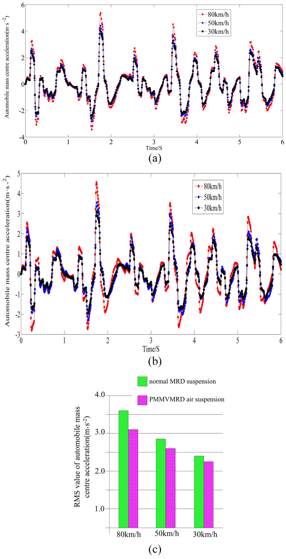
Time-domain simulation results of white noise road surface: (a) simulation results of mass center acceleration of automobile with normal MRD suspensions; (b) simulation results of mass center acceleration of automobile with PMMVMRD suspensions; and (c) simulation result comparison between automobiles with PMMVMRD and normal MRD suspensions.
Conclusion
In order to enhance working performance of air suspension, a PMMVMRD and GSO-PID controlling algorithm are designed. On the basis, three simulation experiments are concluded, and the work in this article is summarized as follows.
To enhance comprehensive performance of air suspension, a novel MRD with a permanent magnet and a magnet valve is designed. First, based on equivalent surface current model, magnetic field model in damping channel is built and then mathematical model of PMMVMRD is built by Bingham model and theories about magnetic valve. Experiments on the novel damper are conducted, and experimental results agree with those simulated by PMMVMRD model. On the basis of newly designed damper model, 4 degree-of-freedom automotive suspension model is built.
In order to enhance optimization velocity of GSO algorithm and avoid local optimum, normal GSO algorithm is developed. On this basis, GSO-PID suitable for PMMVMRD air suspension is designed. The optimized PID controllers by GSO have better factors so that the controlling systems by GSO-PID algorithm have higher controlling accuracy and responding speed. Thus, GSO-PID controlling algorithm can control the pressure in airbags with higher accuracy so that the PMMVMRD air suspensions have better working performance.
Simulation experiments on PMMVMRD air suspension controlled by GSO-PID algorithm are conducted with impact road surface, sine wave road surface and white noise road surface being the input. The experimental results indicate that PMMVMRD air suspension controlling GSO-PID algorithm has good working performance.
Footnotes
Handling Editor: Davood Younesian
Declaration of conflicting interests
The author(s) declared no potential conflicts of interest with respect to the research, authorship, and/or publication of this article.
Funding
The author(s) disclosed receipt of the following financial support for the research, authorship, and/or publication of this article: This study was funded by the Natural Science Foundation of Key Natural Science Foundation of Anhui Provincial Universities (grant no.: KJ2016A799), Natural Science Foundation of Anhui Province (grant no.: 1708085ME127), the Major Natural Science Foundation of Anhui Provincial Universities (grant no.: KJ2017ZD14), the Natural Science Foundation of China (grant no.: 51575001 and 51605003), the Anhui University Scientific Research Platform Innovation Team Building Projects(2016–2018), the 2017 Undergraduate teaching-quality-promotion program of Anhui Polytechnic University-Virtual Simulation Experiment Teaching Center of Automotive Engineering (grant no.: 2017xnfzsyzx01), and the 2017 Anhui Provincial-Level Demonstration Experiment Training Center-Experimental Teaching Center of Automotive Engineering Virtual Simulation (grant no.: 2017sxzx24).