
Abstract
As a kind of novel multifunctional structure with three-dimensional pores characterized by low relative density, lattice structures can attain a lightweight design while maintaining high specific mechanical properties in three-dimensional solid structures. Focusing on the challenge of finding the optimal design of lattice structures in the design object, a design and modeling method of non-uniform three-dimensional lattice structures is proposed while ensuring the selective laser sintering manufacturability. Optimization for cell type, cell size, and strut size distribution of lattices is specified with the mechanical properties analyzed and the material model calculated beforehand. The manufacturing constraints are analyzed and expressed in topology optimization and the optimal distribution of topology optimization results is mapped to the strut size distribution of lattice cells. The rapid and automatic computer-aided design modeling of optimized structures is realized by the parametric definition and assembling of lattice components. Finally, the non-uniform structures are successfully manufactured by selective laser sintering and it is shown by means of finite element analysis and experiments that the proposed design approach can improve the mechanical performance compared to the uniform lattice structure under the same weight reduction. And for the design object in this study, body-centered structure with cell size
Keywords
Introduction
In recent years, with the rapid development of material preparation and forming technology, cellular structures emerge as a kind of novel multifunctional lightweight structure with two-dimensional (2D) or three-dimensional (3D) pores characterized by low relative density. 1 They keep material only in the vital regions of a part to attain a lightweight structure while maintaining the high specific mechanical properties such as strength, 2 shock resistance, 3 heat transfer and insulation, 4 and energy absorption. According to the structural rules, cellular structures can be divided into foams, honeycombs, and lattices, in which the 2D structures mainly refer to honeycombs, 3D closed cell structures are foams, and 3D open-cell structures are lattices.2,5 Lattice-based cellular structures offer stiffer and stronger materials over foams. Compared to honeycombs with 2D pores, the potential fully open 3D interior structures of lattices facilitate multifunctional applications 6 and enable design freedom in the 3D domain.
Various periodic lattice structures have been designed in the past to accommodate the increasing demands of applications requiring specific mechanical properties. 7 Whereas the macro-distribution of the periodic structures is uniform without optimization and does not consider the optimal load transfer path, the lightweight efficiency is not sufficient. Design of lattice structures is restricted by the traditional manufacturing methods. Now the increasing advancement of various additive manufacturing (AM) technologies makes it possible to fabricate complex structures which cannot be processed by conventional technologies. 8 In addition, there exist a few recent studies on the design, processing, and properties of lattice structures manufactured via AM technologies like selective laser sintering (SLS) and selective laser melting (SLM). Daynes et al. 9 generated optimized functionally graded lattice core structures using isostatic lines and experimental tests confirmed the greatly improved stiffness and strength properties of the optimized core structures manufactured by SLS. Chen et al. 10 and Kang et al. 11 designed and fabricated open-cell porous structures with different porosity and pore size values by SLM and SLS, intended to apply as the replacement of human cortical bone and cancellous bone, and the mechanical properties of the porous samples were examined to match with human bone. Leary et al. 12 fabricated the lattice topologies of engineering relevance via SLM and provided an experimental investigation of the mechanical properties of SLM AlSi12Mg lattice structures for optimized process parameters as well as the manufacturability of lattice strut elements for a series of build inclinations and strut diameters. Choy et al. 13 and Maskery et al.14,15 explored the physical characteristics, deformation behavior, and compressive properties of density graded cubic, body-centered cubic, and honeycomb lattice structures fabricated by SLS and SLM for their potential use in impact protection. Related research implies that it is appropriate to use AM to manufacture lattice structures with high geometrical complexity. As a type of AM process, SLS is suitable for the production of complex topological structure, 16 thereby enabling the manufacturing of nearly any shape. 17 Now the challenge is therefore finding the optimal design of lattice structures.
Topology optimization is an important way to achieve the optimal design of lattice structures. The essence of this method is to seek the structural layout with the optimal load transfer path under the action of external force and constraint. 18 At present, the most common application of topology optimization in lattices is the internal structure optimization in a single lattice cell.2,19,20 On the other hand, two-step optimizations for lattice structures21–23 have been conducted with the macrostructure optimized first, and then the results are used as inputs or constraints to optimize the single cell to achieve correlation of the two scales. However, the necessary calculations are complex; lattice cell topology may be selected in advance to improve the efficiency. Based on a library of predefined lattice configurations, Alzahrani et al. 24 and Chang and Rosen 25 utilized the relative density information obtained from a solid topology optimization or a solid-body finite element analysis (FEA) to automatically determine the diameter of each individual strut in the whole structure. The relative density mapping method can optimize the macrostructure, whereas, with each strut as the mapping object, the diameters may be significantly different from strut to strut, which will make it inconvenient for structural modeling, manufacturing, and analysis. We can attempt to topologically optimize the cell distribution of lattice structures with the cell topology analyzed and selected beforehand, so as to realize the optimization design at the macro- and mesoscales of lattice structures.
In this article, we introduce an approach to optimize the design of 3D non-uniform lattice structures for SLS with the lattice cell as the design unit. Optimization for cell type, cell size, and strut size distribution of lattices is specified with the mechanical properties analyzed and the material model calculated beforehand. Considering SLS manufacturing constraints, the optimal distribution of topology optimization results is mapped to the strut size distribution of lattice cells, resulting in non-uniform lattice structure. A rapid and automatic computer-aided design (CAD) modeling auxiliary application for non-uniform lattice structure is developed by the parametric definition and assembling of lattice cells. At last, the approach is validated via FEA and experiments. The overall design scheme is introduced first.
Overview
The purpose of optimal design of non-uniform lattice structure is to improve the overall stiffness while maintaining the same weight reduction ratio as the initial uniform lattice structure under the specified boundary conditions and ensuring the smooth progress of SLS manufacturing without defects. The above content is achieved by the overall design scheme shown in Figure 1.

Overall design scheme.
Equivalent material model establishment of lattice structure
The equivalent material model represents the relationship between topology optimization design variables and structural elastic properties, which is the basis for optimal solution. First, according to the loading conditions, the mechanical properties of different types of lattices are considered, and the optimal lattice type is selected by FEA. Then, the expressions with coefficients for effective elastic properties are deduced by the equivalent strain energy method. At last, the FEA of lattice structures with different sizes of struts is carried out to fit the coefficients and the equivalent material model is established.
SLS manufacturing constraint modeling
During the design process, the structural shape must be considered to satisfy the manufacturing requirements. The manufacturing constraints of SLS include maximum overhanging length, minimum hole size, and minimum section thickness. These constraints can improve the forming quality of designed structures. Manufacturing constraints need to be expressed as functions of optimization design variables, so as to be modeled as constraints in topology optimization.
Equivalent 3D structural topology optimization
Based on the equivalent material model, the lattice structure is equivalent to the continuous 3D structure, the SLM manufacturing constraints are modeled as the topology optimization constraints, and the equivalent 3D topology optimization model can be established. To solve the optimization model, the sensitivity of the objective function is calculated and the aspect ratio distribution matrix of finite elements is obtained by optimality criteria algorithm.
Construction of non-uniform lattice structure
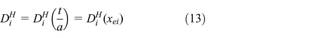
The aspect ratio distribution matrix of finite elements is mapped to the strut size distribution matrix of lattice cells. The rapid and automatic modeling of non-uniform lattice structures is realized with the parametric assembly of lattice components.
Postprocessing, analysis, and experiments
The designed model still needs to be checked and modified to meet the requirements of manufacturing and use. The final results are tested via FEA and experiments. Optimization results of different cell sizes are compared to provide the information support for the optimization of the lattice cell size. The effectiveness of the design method can be validated according to the mechanical properties of the designed structure. The necessity and successful expression of the manufacturing constraints can be verified by observing the quality of the manufacturing results.
Material model establishment of lattices
Analysis and specification of lattice cells
A suitable lattice type is selected first for the 3D solid structure similar to three-point bending beam as shown in Figure 2. The height is

3D solid structure ready for design.
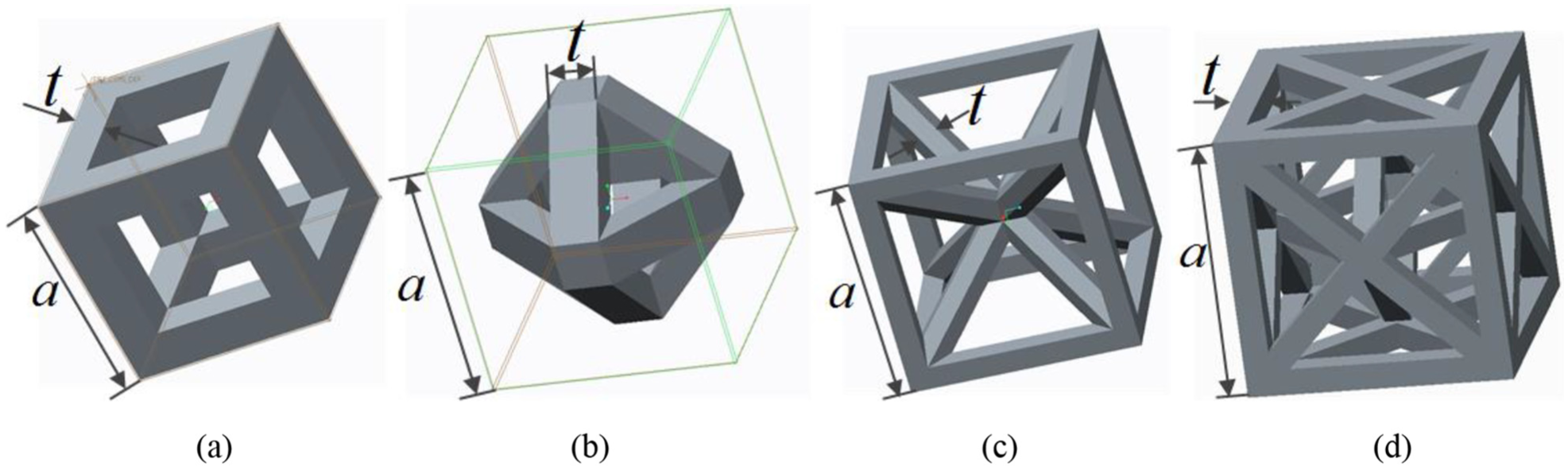
Lattices with cube envelope: (a) edge structure, (b) face-centered structure, (c) body-centered structure, and (d) octet-framed structure.
With reference to the conclusion of Jishi
26
and Zhong and Li
27
on the above several types of lattices from FEA and experiments, we can obtain some information. The edge structure possesses good tensile/compressive capacity, but its performance in the bending and torsion is poor. Capacity of the face-centered structure is general, but is not as excellent as that of the body-centered structure. Body-centered and octet-framed structures provide the best overall performance. These conclusions are further validated in our design object. The four types of lattices in the 3D solid structure shown in Figure 2 are filled uniformly, and the lattice cell size (cube envelope size) is set to
The design formula for relative density is given below

The four types of lattices with the same weight reduction ratio are analyzed in ANSYS under load condition in Figure 2. The simulation results are shown in Figure 4. The maximum displacement and the average displacement on the load area in the vertical direction are compared and shown in Table 1. It can be seen that the maximum and average displacement of body-centered structure are the smallest, which represents that the comprehensive performance of body-centered lattice in compression and bending is excellent and it can be a good choice for the filling of 3D solid structure in Figure 1.

Simulation results of (a) edge structure, (b) face-centered structure, (c) body-centered structure, and (d) octet-framed structure.
Structural displacement of different lattice types.

Prediction of effective elastic properties
The effective mechanical properties of lattice structures are the main factor to be concerned when designing, for the topology optimization of the equivalent continuum is realized based on the sensitivity analysis of the effective performance. The methods of prediction of effective elastic properties for lattice structures mainly include Gibson method, equivalent strain energy method, and asymptotic homogenization method.
The method of Gibson and Ashby 28 establishes the stress–strain equation for a unit cell according to the deformation compatibility condition and obtains the analytical forms of effective properties. It is suitable for simple and regular cell structures such as rectangle and hexagon, but not for complex 3D lattice structures.
Asymptotic homogenization method29,30 is a rigorous mathematical method based on two-scale asymptotic expansion, which can obtain effective properties of cells with arbitrary structure. However, its realization is complicated, and finite element programming is needed for specific cell structure. The method can yield numerical results, while it cannot obtain the relations between elastic properties and structural parameters. At the same time, the approach is valid only when the lattice cell size is very small compared with the macrostructure, 31 which is not conducive to manufacturing.
The equivalent strain energy method calculates the effective elastic constants by analyzing the strain energy of a single cell under different strain boundary conditions. This approach does not require additional programming calculations and is suitable for orthotropic lattice structures. 32 With reference to the research of Theerakittayakorn et al. 33 on the equivalent strain energy method, the effective elastic constants of the body-centered lattice structure can be expressed as the relationship of the geometric parameters of cells, the elastic constants of the material, and some dimensionless factors. The results of theoretical analysis may be different from the practical ones; therefore, the FEA results of lattice structures with different strut sizes are used to fit the dimensionless factors to determine the exact expressions of effective elastic properties. Details are introduced below.
The elastic constitutive relation of body-centered lattice structure can be written as

where

where
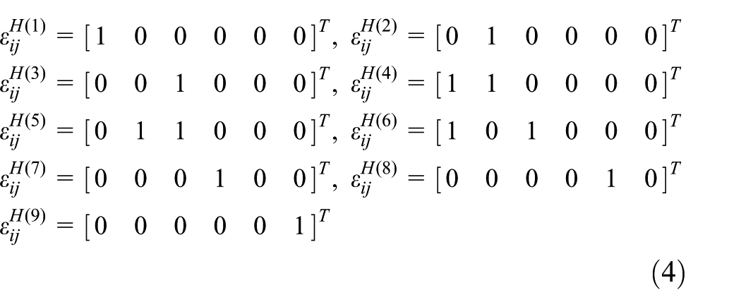
the terms of

The specific values of

where
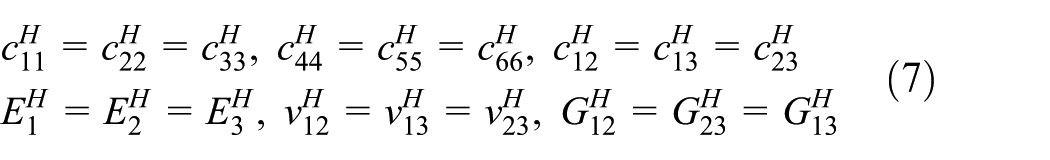
Considering the cubic symmetry of the properties of a body-centered lattice cell, there exist some relations among the elastic constants as follows
Then the effective Young’s modulus

where

In the conventional solid isotropic material with penalization (SIMP) topology optimization, the elastic properties are expressed as a function of the relative density
Analysis of Young’s modulus and Poisson’s ratio is shown in Figure 5(a). The dotted lines represent the deformation of the structure. The strain in the z-direction is

Geometry and boundary conditions for the analysis of (a) Young’s modulus and Poisson’s ratio and (b) shear modulus.
Analysis of the shear modulus is shown in Figure 5(b). The shear strain is
The curves of the effective Young’s modulus, Poisson’s ratio, and shear modulus versus the aspect ratio of lattice cells are shown in Figure 6. The range of aspect ratio is 0.06–0.2, which is determined by the manufacturing constraints of lattice structures.

Curves of effective mechanical properties: (a) Young’s modulus, (b) Poisson’s ratio, and (c) shear modulus.
Based on the analysis results, curve fittings are performed on equation (9), yielding the exact formulas of the effective Young’s modulus, Poisson’s ratio, and shear modulus
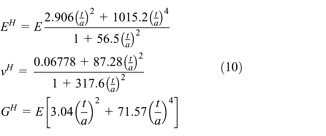
where
With the content above, the elastic constitutive relation

The formula is valid for the body-centered structure with the aspect ratio range of 0.06–0.2, which is the boundary of the manufacturing constraints.
Manufacturing constraint modeling
The manufacturability of the structure is an important basis for the design of lattice structure. SLS is a kind of AM technology and is suitable for the manufacture of a non-uniform body-centered lattice structure. When designing the lattice structure, it is necessary to consider the SLS manufacturing constraints and implement them in the optimization model. Since the aspect ratio is used as the design variable in the optimization, the constraints need to be expressed as functions of the aspect ratio.
Maximum overhang length H
For the parts with overhang structure, direct sintering may result in local shape failure, mainly reflected in that the overhang shape will move and flip with the scraper since there is no support below. Generally, it is considered to add support in advance to ensure the stability of the process. And the need for support is determined by the tilt angle and length of overhang.
In the design of body-centered lattice structure, it is difficult to remove the support inside the lattice cell. So it is necessary to limit the tilt angle and the overhang length to avoid the support structure. The tilt angle of diagonal strut in body-centered lattice is 45 degree, and the support is not necessary for diagonal strut. The overhang length

The body-centered lattice component.
Minimum hole size R
For holes with extremely small diameters, during laser scanning of the hole profile, the process will have a considerable impact on the structure near the hole. The powder in the vicinity of the hole is heated to be melted or semi-melted, thereby causing the hole to be blocked. Therefore, the holes must be larger than a certain size
The triangular hole size
Minimum section thickness T
Design of structural section thickness should ensure that the sintered parts meet the required strength. The section thickness should not be too small because poor strength leads to damage on thin sections by a scraper. So the section thickness should be greater than a certain value
The straight strut size
Equivalent 3D structural topology optimization
Modeling
Topology optimization design of lattice structure is based on the 3D SIMP method. The whole structure is divided into finite elements, and the aspect ratio is introduced into each element as a design variable. The relationship between design variables and the overall structural mechanical properties is established by representing the effective material properties as a function of aspect ratio. The goal is to solve the optimization model to obtain a design variable distribution that maximizes the overall stiffness in a given weight reduction and then map it to the lattice cells to construct a non-uniform lattice structure.
First, with the element aspect ratio

The objective function
Based on the finite element method,
37
the element stiffness matrix

The global stiffness matrix

Finally, the structural displacement matrix
The constraint
Solution
When solving the established model, there may exist numerical difficulties such as local minima and mesh dependency. The design variable filter method 38 can be used to mitigate the issues and the filter function is defined as
where
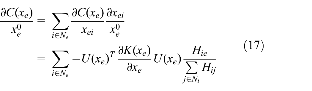
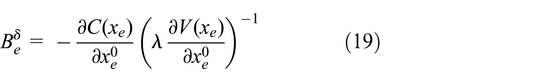
The filtering is also conducted in sensitivity analysis, and the sensitivity of the objective function to the design variable is
Based on the filtered sensitivity, the optimality criteria method is used to update the design variables 39
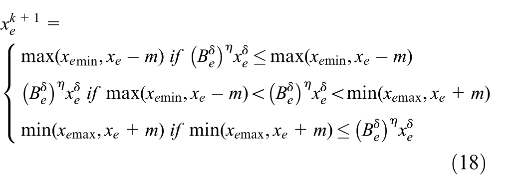
where
The value of the Lagrange multiplier
3D topology optimization is realized in MATLAB and the details have referred to Kai Liu’s code. 32
Lattice structure construction
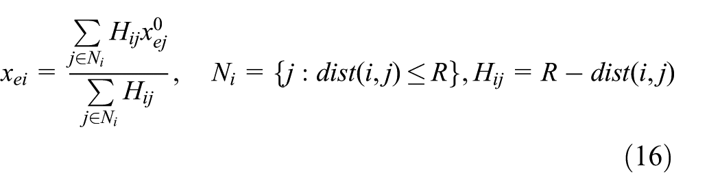
Mapping of strut size distribution matrix
The aspect ratio distribution of elements is obtained from topology optimization. The strut size distribution matrix of lattice cells can be obtained by calculating the mean value of the elements enclosed by each cell. The details are shown in Figure 8.

Illustration of map from elements to lattice cells.
Determination of input parameters
Length, width, and thickness of the design domain are
Determination of the arrangement of lattices
With the upper-left corner
Solution for the strut size distribution matrix of lattice cells
For the lattice

The boundary sequence where the lattice
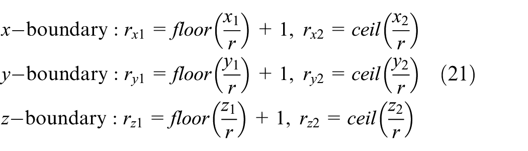
Then the strut size of the lattice
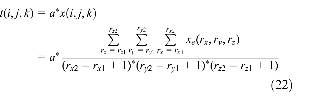
The strut size distribution matrix of lattice cells can be obtained with the iteration of all lattice cells.
Non-uniform lattice structure modeling
With the arrangement and strut size matrix of lattice cells as input, modeling of a non-uniform lattice structure is carried out. PTC Creo is chosen as the structural modeling CAD software. With the support of Pro/Toolkit library of Creo, we can develop the automatic modeling auxiliary application for the parametric assembly of a non-uniform lattice structure.
The general flow of non-uniform lattice structure modeling is shown in Figure 9. First, we need to carry out geometry modeling of a single lattice component, establish parameters, relations, and datum of the lattice features, and so on to complete the creation of the parameterized lattice component. The body-centered lattice component is shown in Figure 7. The parameters, dimensions, relations, and component datum in the diagram are shown in Table 2, which constitute a parameterized lattice component.

Flow chart of non-uniform lattice structure modeling.
Parameters, dimensions, relations, and datum of lattice component.
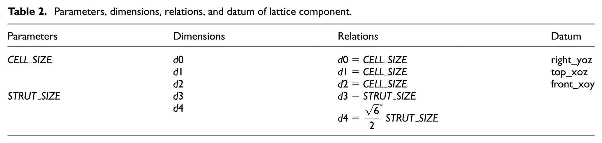
CELL_SIZE is the cube envelope size of the lattice. STRUT_SIZE is the diagonal strut section size, which is determined by the strut size distribution matrix.
Second, the assembly model is created and the assembly datum is generated. The type of datum includes the default datum plane and the offset datum plane. Default datum plane is the standard orthogonal plane in the default coordinate system of the assembly model, which is the reference of the initial lattice component. Offset datum planes are referred by other components. Based on the default datum, the offset value and arrangement number must be determined. The offset value of the lattice
At last, the lattice components are assembled into the assembly model. Assembly constraints are defined with the datum aligned. The lattice components are regenerated in the assembly with parameter assignment. And the non-uniform body-centered lattice CAD model is obtained with the circular assembly definition of all components.
Results and discussion
Design results
According to the SLS manufacturing constraints provided by the manufacturing service, the maximum overhang length
In order to obtain a lattice structure with the volume fraction (or relative density) of 0.4, the lattice cell size
Topology optimization results and lattice structural models.

The structural models of different lattice cell size

Postprocessing of the optimized lattice structural model.
It can be seen from Figure 10 that the structural model after strut size mapping, CAD modeling, and postprocessing is intact without defect, and it reflects the distribution results of topology optimization well. It can also be noted that different cell sizes result in different optimization results because the aspect ratio range of topology optimization is not the same under the same manufacturing constraints. And it is necessary to perform FEA and compare the performances of the optimized structures to determine which type of cell size is better.
FEA simulations
Under the load condition of Figure 2, FEA simulations of the uniform and non-uniform lattice structures are conducted and the average displacement in the vertical z-direction of the load area is obtained as
Different lattice cell size
Under the same weight reduction, the flexural stiffness of the optimized non-uniform lattice structure is significantly improved with respect to the uniform structure. The largest increment degree is at
Different lattice cell size

Flexural stiffness of uniform and non-uniform lattice structures with different cell sizes.
Manufacturing and experiments
The design method is further verified via the manufacture and experiments of the body-centered lattice structures. The uniform and optimized non-uniform body-centered lattice structures with cell size

Lattice structures manufactured by SLS: (a) uniform lattice structure and (b) non-uniform lattice structure.
Three-point bending tests are carried out on the two manufactured structures using a WDW-100 electronic universal testing machine. The test is shown in Figure 14, the span of the fixture is
The force–displacement curves recorded are shown in Figure 13. Figure 14 provides the deformation processes and failure modes of uniform and non-uniform lattice structures during three-point bending tests, and it corresponds to different stages in Figure 13. Initially, in stage a(1) and stage b(1), the two types of lattice structures both exhibit linear elastic behaviors with uniform displacements at the loading point. In stage a(2) of the uniform lattice structure, the linearity begins to terminate at the plastic collapse of local cells, and highly non-linear permanent deformation in lattice cells at the loading point is observed. While for non-uniform lattice structure in stage b(2), it shows relatively linear stiffness and little plastic behavior with global deformation of the structure. In stage a(3) of the uniform lattice structure, failure of lattice cell crushing can be observed around the loading point. While in stage b(3) the non-uniform lattice structure still exhibits global deformation of linear stiffness until the sudden damage happens to break the structure into two pieces with brittle failure characteristics. The brittle damage mode of non-uniform lattice structure indicates that after the optimization the stresses are distributed uniformly within the structure, not like the local plastic damage of uniform lattice structure. The reason for the brittle damage can also be investigated by observing the damage area of lattice struts after bending tests using an optical microscope. The optical micrographs are shown in Figure 15. It can be observed that there exist some partially melted nylon powder particles on the damage area which may induce defects inside of the strands. It is an important reason which caused the brittle damage.

Force–displacement curves of lattice structures recorded in three-point bending test.
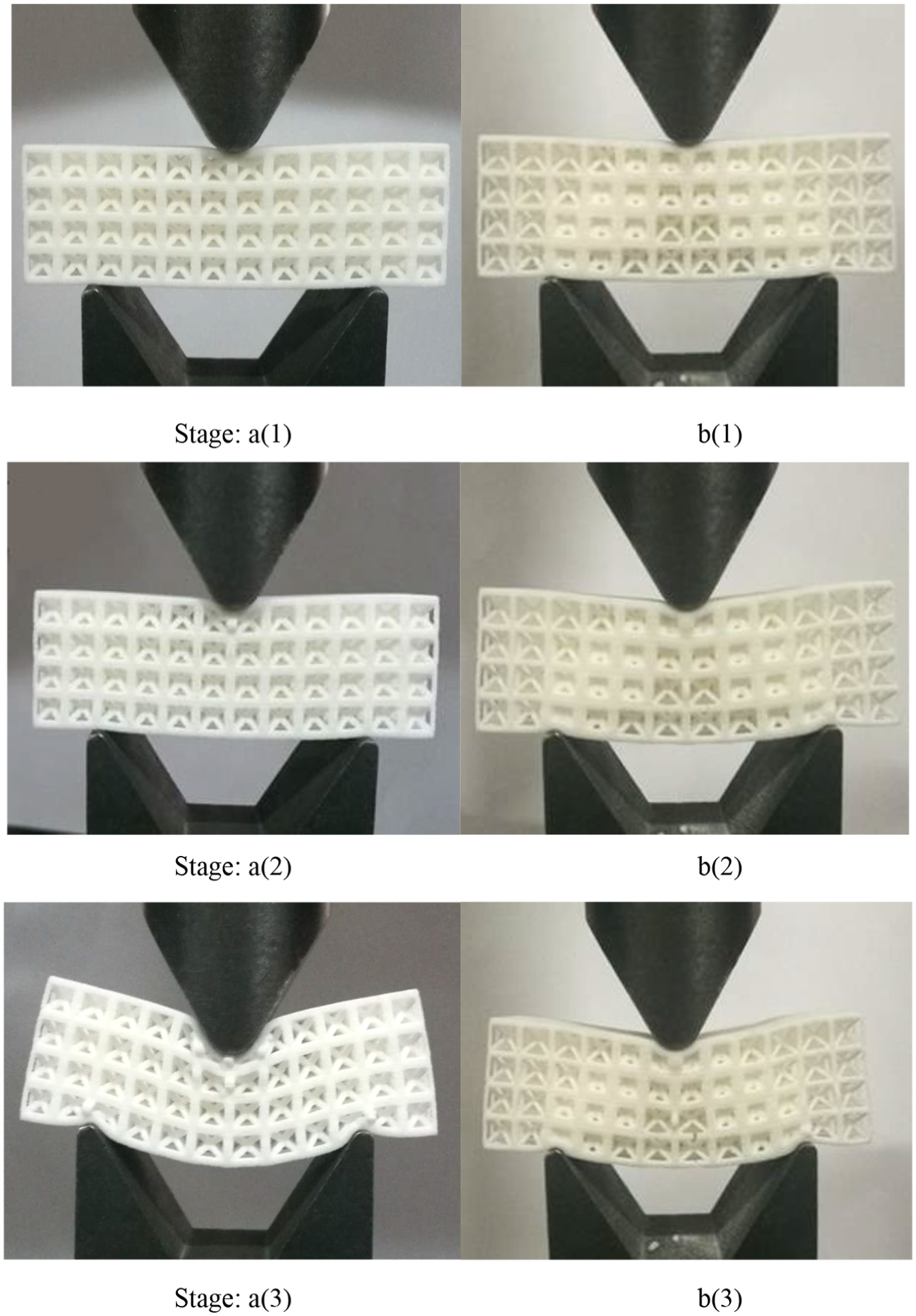
Deformation processes of uniform and non-uniform lattice structures during three-point bending tests: a(1) linear elastic stage of uniform lattice, b(1) linear elastic stage of nonuniform lattice, a(2) highly non-linear deformation of uniform lattice, b(2) little plastic behavior of nonuniform lattice, a(3) lattice cell crushing of uniform lattice, and b(3) sudden damage of nonuniform lattice.

Optical micrographs of a strut damage area after bending test at different magnifications: (a) optical micrograph with magnification 50, (b) optical micrograph with magnification 100, and (c) optical micrograph with magnification 200.
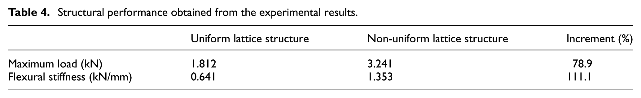
From Figure 13, we can also obtain the flexural stiffness at the initial linear elastic stage and obtain the maximum load of the three-point bending test. The maximum loads of uniform and non-uniform lattice structures are
Structural performance obtained from the experimental results.
Comparison of stiffness and mass from the experimental and FEA results is shown in Table 5. For uniform and non-uniform lattice structures, the FEA results are
Comparison of stiffness and weight from the experimental and FEA results.

FEA: finite element analysis.
The error of stiffness and mass is caused due to three reasons. The first reason is that the material properties of the manufactured structure can be affected by the fabrication method and the manufacturing parameters, especially for the layer-by-layer manufacturing process of AM. There exist deviations in the modulus and density between the actual values and the ones provided by the manufacturing service. The second reason is that the dimensions of the manufactured geometry and the designed geometry used in FEA are not exactly the same. Because of the layer-by-layer principle, the AM-fabricated model generally has the stair-step irregularities corresponding to the slicing process. 40 It can be seen from Figure 12 that the surface of the strut fabricated by SLS is irregular and rough, and it becomes more significant for the thin strut in the lattice structures. The discrepancies in dimensions will lead to inaccurate simulation results in the stiffness and mass. The third reason is the error of the load condition between the practical experiment and the theoretical analysis. The load area in the experiment is varied during the deformation processes and in the initial stage it is smaller than the area set in design and FEA, which will lead to the overestimation of flexural stiffness. All the deviations still need to be further investigated in the future to refine FE models to obtain more accurate results.
Conclusion
In this article, an optimal design and modeling method of 3D non-uniform lattice structures is presented. Compared to the uniform lattice structures, this method can improve the mechanical performance and simultaneously ensure the manufacturability of the structure. Realization of the method begins with the optimization of the lattice cell type. Based on the equivalent material model of lattice structures, the topology optimization of equivalent continuous 3D structures is conducted with manufacturing constraints described and solved in a mathematical model, and the optimal result is mapped to the strut size distribution matrix. The rapid and automatic CAD modeling is realized by the parametric definition and assembling of lattice components. Finally, the analysis and comparison of uniform and non-uniform lattice structures is carried out via FEA, manufacturing, and experiments. Based on the results, several aspects are observed:
The CAD models and the manufactured results of the optimized lattice structures are intact without defects, and they are consistent with the distribution results of topology optimization. The successful expression of manufacturing constraints is verified.
The mechanical performance of the optimized non-uniform lattice structure is better than that of the uniform lattice structure at the same weight reduction and the efficiency of the proposed method is validated.
Different lattice cell size
In three-point bending tests, the uniform lattice structure exhibits local plastic damage of lattice cell crushing, while the optimized non-uniform lattice structure possesses brittle failure characteristics. The phenomenon indicates that after the optimization the stresses are distributed uniformly within the non-uniform lattice structure.
The design and modeling method still has shortcomings that require further work to be researched. Design and modeling for practical complex structure needs to be considered to improve the engineering application. And in view of the multifunctional characteristics of the lattice structures, multidisciplinary optimization can be performed to meet different requirements.
Footnotes
Handling Editor: Farzad Ebrahimi
Declaration of conflicting interests
The author(s) declared no potential conflicts of interest with respect to the research, authorship, and/or publication of this article.
Funding
The author(s) disclosed receipt of the following financial support for the research, authorship, and/or publication of this article: The authors are grateful for the financial support of this work by the National Natural Science Foundation of China (No. 51505488).