
Abstract
The precise positioning design of upper limb prostheses is important for patients with upper limb disability. In this study, we propose an upper limb prosthesis with a negative pressure design. Mechanical analysis is performed to obtain the force and moment equilibrium equations. Then, the individual discipline feasible method is performed to decouple the original problem into a three-sub-discipline problem. A minimum of three shoulder straps of tension is obtained during optimization using the Isight harness scheme. The prosthetic socket can be firmly attached to the human body. Further experiments verify that the proposed device meets the basic requirements of wearing.
Introduction
Upper limb prostheses are typical shoulder prostheses that provide additional assistance and protection to patients with upper limb disability, thereby increasing the quality of life of these patients.1,2 With the increase in the number of patients with upper limb disability, upper limb prostheses are being developed in large numbers. However, shoulder prostheses in the market are largely identical with minor differences. Such devices usually need improvement in positioning accuracy to prevent dislocation. Upper limb prostheses with a negative pressure design could solve this problem.
For patients with severed shoulder(s), two prosthesis wearing shapes are currently available: in-line and splayed strap shapes. The in-line strap shape is common for clinical use. Using three straps with pulling function, the splayed strap shape controls hand and elbow motion with the stump and shoulder, thereby providing continuous movement. The straps on existing shoulder prostheses have three functions: (1) to suspend the upper limb prosthesis, fixing the prosthesis to the stump; (2) to operate the upper limb prosthesis, thereby optimizing body dynamic source; and (3) to improve the wearability of upper limb prosthesis.3,4
In this study, we propose an upper limb prosthesis with a negative pressure design. Mechanical analysis is performed to obtain the equilibrium equation of forces and moments. The forced state of straps is optimized by designing the value ranges of input variables. The results of the genetic algorithm (GA) prove that the proposed device meets the basic requirement of prosthesis wearing.
Mechanical analysis of two common wearing devices
The upper limb prosthesis with a splayed strap shape is shown in Figure 1(a). The origin of the coordinate system is settled at the central point of the central hoop (Figure 1(b)). Fn (n = 1, 2, …, 5) is the internal force of these five straps. According to the bases of force balance, the corresponding equations are given below.

The upper limb prosthesis with a splayed strap shape: (a) the splayed strap shape and (b) the coordinate system of splayed strap shape.
Based on the five-force balance, the following equation is derived:


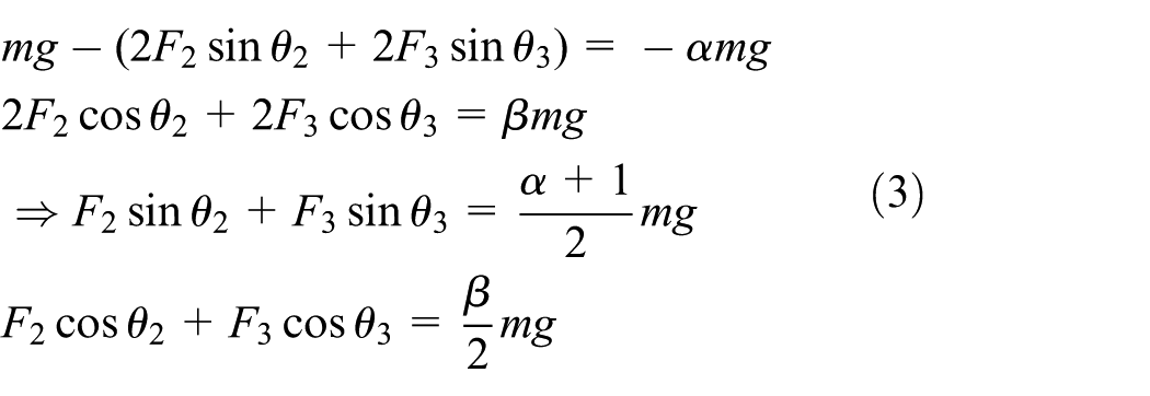
The force horizontally rightward is 2F2cosθ2 + 2F3cosθ3, and the force vertically downward is mg – (2F2sinθ2 + 2F3sinθ3). The force on the stump vertically upward is mg – (2F2sinθ2 + 2F3sinθ3), and the force on the stump horizontally leftward is 2F2cosθ2 + 2F3cosθ3.
The terms “horizontal” and “vertical” indicate the forces of the receiving cavity in the horizontal and vertical directions, respectively (except for the force of the stump). “Residual limb” indicates the interaction force between the residual limb and the receiving socket. Socket force is balanced; thus, the “stump,” respectively, with the force of “level” and “vertical” is equal and opposite.
Assuring that the combination is firm, the minimum force between the stump and the prosthetic socket is set as follows: the force vertically upward is αmg and the force horizontally rightward is βmg. Therefore, we assume that the connection between the stump and the prosthetic socket is firmly combined if the force vertically upward is αmg and the force horizontally rightward is βmg. According to the assumption, the equations are given as
Set

Figure 2 demonstrates the upper limb prosthesis with an in-line strap shape. Two rectangular coordinate systems are set on the prosthesis and body.

The upper limb prosthesis with an in-line strap shape.
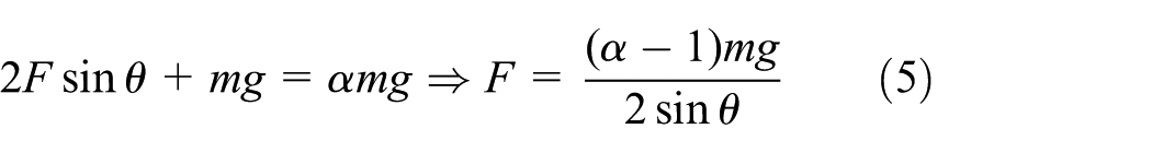
The force horizontally rightward is 2Fcosθ and the force vertically downward is 2Fsinθ + mg. The force on the stump vertically upward is 2Fsinθ + mg, and the force on the stump horizontally leftward is 2Fcosθ.
According to the assumption

Mechanical analysis of three straps
Figure 3 demonstrates the upper limb prosthesis with three straps. Three rectangular coordinate systems are set on the strap.

Three-strap design.
The force horizontally leftward is 2F1 + 2F2cosθ + 2F3, and the force vertically downward is 2F2sinθ + mg. The force on the stump vertically upward is 2F2sinθ + mg, and the force on the stump horizontally rightward is 2F1 + 2F2sinθ + 2F3.
According to the assumption, the equations are given as

Set

Set

For the cases of one shoulder strap and three shoulder straps, the values of F2 are the same. F1 should be the smallest shoulder strap force. For the case of five straps, there are too many angles and forces, and an approximate force analysis is used to derive the force size. In combination, the three straps are more labor-saving.
Upper limb prosthesis with a negative pressure
The upper limb prosthesis with a negative pressure is shown in Figure 4. It consists of an upper limb prosthesis, a prosthesis socket, three pressure-distributing straps, and a negative pressure device. The numbers in Figure 4 represent the following: 1—fossa axillaris surrounding strap (Strap 1); 2—rib cage strap (Strap 2); 3—waist strap (Strap 3); and 4—retaining valve. Strap 1 starts from the fossa axillaris of the uninjured side, goes behind the neck, and finally rests on the prosthesis socket. The negative pressure in the prosthesis socket is formed by the retaining valve, connector, and air extractor to vacuum out the air in the socket so that the prosthesis socket is attached to the stump. The upper limb prosthesis with a negative pressure can accurately position the prosthesis.

The upper limb prosthesis with a negative pressure.
To describe the relations between the forces qualitatively and to simplify the calculation, we made the following assumptions: the part of Strap 1 behind the neck is linearly horizontal; the part surrounding the fossa axillaris is linearly vertical; and Strap 3 is also linearly horizontal. These assumptions are reasonable because the angular deviation is small (Figure 4). Therefore, the components of forces and moments are also small.
Force equilibrium equation


The force F1 in equations (10) and (11) refers to the force on the horizontal part of Strap 1, which is behind the neck (Figure 4). F2 and F3 are, respectively, the tension of the shoulder straps 2 and 3.
Fb is the body of the cavity to accept the force. The intersection angle between Strap 2 and the horizontal direction is 30°. Substituting the value into the equation, we obtain

Then, we obtain


Equations (12) and (13) suggest that the internal forces of the three straps and the composition force of the stump to the body share a linear relation. A relation also exists among F1, F3, and F2. To guarantee a minimum force Fbmin between the socket and the stump so that the prosthesis does not drop, the values of F1, F2, and F3 should be well arranged.
To be generalized, we set sinθ2 = a, then
The equations above turn into

Thus
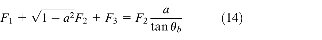

where θb is the intersection angle between the composition force of the prosthesis and the body and the horizontal direction. Considering the dynamic balance of the prosthesis–body system, we can calculate θb and a, together with F1, F2, and F3.
Setting
The moment balance equation is as follows

where F1 is the composition of the forces of Strap 1 to the body, not the force on the horizontal part of Strap 1 and l1, l2, l3, and lb represent the shoulder strap 1 pull the arm, shoulder strap 2 pull the arm, shoulder strap 3 force arm, and the body of the prosthesis to accept the force of the arm, respectively.
In this model, the changes in the arm of forces do not influence the result obtained by deducing the equations of force balance. Thus, the value in the three straps and the angle of Strap 2 are calculated using the force balance equations. The moment balance equations are only used to calculate the arm of forces (the relative position among three straps).
Optimization method
Optimization factors
Setting F = f(F1,F2,F3) as the goal of optimization, we obtain a multi-objective optimization. Otherwise, the goal is to turn into a single-objective optimization by describing F with the combination of F1, F2, and F3.
We set the minimum value of force between the socket and the body, Fj, as the constraint condition. This step prevents F1, F2, and F3 from being infinitely small and keeps the prosthesis attached to the human body.
Then, we obtain two force balance equations and three moment balance equations. The values of F1, F2, F3, Fj, and c are unknown, and all other values are measurable or design variables. The length of the arm of forces in each coordinate system should be correlated by equations.
In consideration of the balance of forces and moments, a set of equations are listed in an approximate condition. The two force balance equations are given by equations (17) and (18), and the three moment balance equations are given by equations (19)–(21)


Method 1
Force balance equations (17) and (18) are used to eliminate θJ

The constraint condition is FJ ≧ Fo, and Fo is the minimum to keep the prosthesis fixed to the human body.
We set f =f(F1,F2,F3) as the goal of optimization; therefore, min f = F1 + F2 + F3. The design variables are θ2, F4, F1, F2, and F3; θ4 is a measurable variable and is regarded as known

The limitation of Method 1 is that the position of Strap 3 is unknown, with all other design variables optimized.
Individual disciplinary feasible method
The individual discipline feasible (IDF) formulation,5,6 also called “optimizer-based decomposition” 7 or “single-SAND-NAND,” 8 avoids the need for a complete multidisciplinary analysis at each iteration of the design process. If the number of coupling variables is relatively small, the IDF method is applicable and provides good results.9,10 The IDF method presents the advantage of being implementable in a network. 11 This particularity can considerably improve the efficiency of the method (calculation time is reduced). 12 This method decomposes the main problem into several subsystems. This decomposition method considerably increases the number of variables but improves the optimization efficiency (parallelization is possible). 13
Deducing an expression of F1, F2, and F3 that only contains known variables is complicated; thus, the IDF method is proposed. The main idea of the IDF method is to introduce auxiliary variables so that the original issue is decoupled to a three-sub-discipline issue.
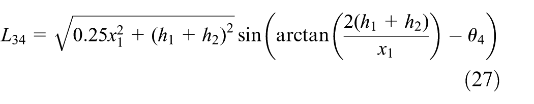
As shown in Figure 5, x1 is the approximate distance from the socket’s equivalent stress point to Strap 1’s coordinate origin. L12 indicates the force arm of F1 to the second point.

Coordinate system to determine the position of three straps.
Therefore

λ2 is the intersection angle formed in the horizontal direction, equivalent stress point, and Coordinate Origin 2.
λ3 is the intersection angle formed in the horizontal direction, equivalent stress point, and Coordinate Origin 3.
Then


Method 2
The force balance equations (7) and (8) can be simplified to


Equations (16)–(18) turn into

The deduced result is as follows


The IDF method is employed to solve these equations, and the issue returns to the issue before decoupling:
Issue before decoupling:

where
The three sub-disciplines are the equations of C1, C2, and C3 listed above.
Example of optimization
Isight is a powerful computer-aided optimization platform used to integrate and manage complex simulation processes. With this platform, various optimization algorithms are employed to automatically explore the optimization program. 14 According to the equations deduced above, Isight version 5.8 is used for the straps’ parameter design optimization. Figure 6 illustrates the task flow chart of Isight. Three combinatorial optimization components and a calculator are used for optimization analysis. The ranges of design variables are shown in Table 1.

The task flow chart of Isight.
Ranges of design variables.

The objective function is

The constraint condition function is


The values of C1, C2, and C3 are the constraint reflection of the consistency degree of the auxiliary variables a1, a2, and a3 with the actual values of F1, F2, and F3, respectively.
Optimization process
The multi-island genetic algorithm (MIGA) is essentially an improvement of the GA in terms of global solution ability and computational efficiency. 15 The operations of the MIGA algorithm include fitness, gene coding, population, subpopulation/island, migration, selection, crossover, and variation. 16 The commonly used coding methods include binary encoding, gray encoding, real coding, and symbol encoding algorithms. Compared with other encoding methods, gray coding can improve the local search ability of the GA. The algorithm divides each population into several island subpopulations and then performs GA operations on each island. In addition, individuals are randomly selected to migrate between islands to achieve the diversity of the entire population. 17
Considering the high demand of positioning of the per-limb prosthesis with a negative pressure, we use gray coding to simplify the calculation complexity of MIGA. Seven design variables were selected based on the IDF. The gray coding multi-island genetic algorithm was used to optimize the shoulder strap pull force. The final optimization results were compared to verify whether the proposed wear style satisfies the basic requirements.
Result
Sensitivity of design variables toward the objective function
The sensitivity of design variables toward the objective function is calculated with the DOE component pack in Isight. The results are shown in Figures 7 and 8.

Design variables on the main effect of the objective function.

Design variables on the objective function Pareto diagram.
Figure 7 indicates that a3 significantly influences f, indicating a linear correlation between them. Figure 8 demonstrates that the contribution of a3 to f is as high as 28%. Blue represents the positive effect and red represents the negative effect.
Optimization of design variables
After the optimization component runs 1001 times, the result is converged. The design variables are optimized as shown in Table 2.
Optimization of design variables.

Clinical verification proves that the force of all three straps is 35.721 N, which decreases to 20.2534 N after optimization, whereas Fj is 65.782, which is large enough to keep the prosthesis attached to the stump. Therefore, the patients receive improved comfort.
Conclusion
A mechanical analysis of the straps is performed, considering the fact that the prosthesis should be attached to the stump. The objective function is established based on the minimum value of the total strap tension. The IDF method is used to decouple the original issue into a three-sub-discipline issue, and the sensitivity of the design variables to the objective function is established. The mechanical analysis results show that the strap tension a3 has the largest influence on f, followed by the negative pressure F4, the strap tension a2, and the strap tension a1. The vertical distance between the second and third coordinates is h2, the intersection angle between Strap 2 and the horizontal direction is θ2, and the vertical distance between the first and second coordinates is h1.
After the final optimization by the optimization component, we obtain the optimized design variables. The total strap pulling force after optimization is significantly smaller than it was before. The constraint condition value meets the requirement for fixing the prosthesis and the stump together. This study provides a theoretical foundation and guideline for designing upper limb prosthesis straps.
Footnotes
Handling Editor: Assunta Andreozzi
Declaration of conflicting interests
The author(s) declared no potential conflicts of interest with respect to the research, authorship, and/or publication of this article.
Funding
The author(s) disclosed receipt of the following financial support for the research, authorship, and/or publication of this article: This project was supported by the National Natural Science Foundation of China (Grant No. 51335004).