
Abstract
Regular surface-maintenances are necessary for high structures to increase service life. The traditional manual operation has shortcomings like limited maneuverability, poor operating quality, low operating efficiency, and high risk of physical harm, which makes it urgent to develop wall-climbing robot for carrying out surface-maintenances of high structures with high efficiency, low cost, and good protection of operators. In this article, we have developed a wheeled wall-climbing robot that uses a permanent magnet adhesion system to climb on large steel surfaces. Wheel traction to avoid slippage is increased by using inflated rubber tire while maintaining a desired air gap for the magnet system. Research is directed at designing a lightweight magnet system to provide an optimum adhesion force and at determining required tire pressures to maintain a specified air gap between the magnets and the surface.
Keywords
Introduction
Ships, offshore platforms, petroleum storage tanks, and sea-crossing bridges are important structures to industry and economy. They make sure global distribution of products, energy supply, and transportation in the world, which is the basics of modern life. 1 Currently, those structures are as high as dozens of meters, even over 100 m. In addition, they are usually located at the seaside or directly operating in the sea. This special environment causes the structures suffered from many problems, such like corrosion, perish, and biofouling.2,3 Taking ships, for example, biofouling not only weakens strength of hull but also leads to more fuel consumption, which can get an increment as much as 25%–30%. 4 In order to keep them working for longer time, it is very necessary to conduct regular surface-maintenances to those high structures at some intervals, including non-destructive testing, removal of rust, and stripping of corrosion.
Traditionally, the surface-maintenances are carried out manually by operators. Since the target surface is always located at a high altitude, it is a major challenge of accessing to the target surface, especially with heavy operating tools. Usually, scaffolding and aerial working platform are used to help operators to reach the desired area, which causes an ineffective preparation process with additional cost of time and money. Moreover, the manual surface-maintenance operation has other critical shortcomings, such like limited maneuverability, poor operating quality, low operating efficiency, and high risk of physical harm.5–9 Additionally, in some cases like nuclear industry and chemical industry, the working environments could cause serious harm to operator’s health.10–12 Therefore, developing a wall-climbing robot to carry out surface-maintenances of high structures with high efficiency, low cost and good protection of operators is extremely necessary.
Technologies of wall-climbing robots have been researched for a few decades.5–9,13–39 Considering the high working surfaces, adhesion-locomotion system plays an important role in a wall-climbing robot. On one hand, it provides an adhesive force to produce enough friction for sustaining the weight of robot and payloads, which should not be too great to make robot stuck in place or locomotion jerkily. On the other hand, it provides a climbing movement on the surface with high velocity and maneuverability. Obviously, adhesion-locomotion system determines the operating performance and payload capacity of a wall-climbing robot, which is the research focus in this field. Until today, there are different adhesion-locomotion principles for wall-climbing robots. Considering the surface-maintenances requiring good capacity of payload, high speed, and maneuverability, permanent magnetic wheel-type adhesion-locomotion system is the most preferred choice in the design of wall-climbing robot, which works on ferrous surfaces.1,8,38 Cai et al. 38 presented a wall-climbing robot with three magnetic wheels. The magnetic wheel includes two permanent magnetic rings magnetizing radially in opposite directions, a copper ring and a yoke. The arrangement constitutes a magnetic circuit with most of the magnetic flux flowing through the surface and then produces a larger adhesive force compared to a whole piece of permanent magnetic ring. Easily to understand, only the part near the surface is effective to produce adhesive force in a magnetic ring, which means most part of the magnetic ring does not function but increases the weight of robot. To make best of the magnet, Howlader and Sattar 8 mounted flat permanent magnets beneath the chassis. Without magnetic flux concentrator, quite a part of magnetic flux leaks into the air, which is still not good enough for getting a large adhesive force with a lightweight magnet. To solve this problem, Ross et al. 5 arranged permanent magnets in a Halbach array. This array can form a one-sided strong magnetic field and then produce a large adhesive force. However, considering the adhesive force as large as several thousand newtons, it is not convenient to assemble permanent magnets with a Halbach array, which costs a lot of time and money. Furthermore, the above wheels all had a hard outer-part and caused a small deflection under the contact force from the surface, which leads to a small friction and makes the robots easily to slip.
In this article, a permanent magnetic wheel-type adhesion-locomotion system for water-jetting wall-climbing robot, which uses the high-velocity water jet to clean rust, biofouling, and corrosion, 40 is presented. An annular-sector shaped magnetic adhesion system is used, which performs well in producing a large adhesive force with a lightweight magnet. In addition, a pneumatic tire is employed to increase the friction between wheel and surface, which is much lighter than solid one. However, there is a coupling interrelationship between the magnetic adhesion system and the pneumatic tire, which must be considered in order to determine two important designed parameters of wall-climbing robots, initial air gap and inflation pressure. Here, initial air gap is used to set the assembling dimensions between the magnetic adhesion system and the robot, and inflation pressure is used to set the air pressure inside the tire before robot climbing on the surface. Clearly, the adhesive force produced under an initial air gap causes a tire deflection under the inflation pressure, which then reduces the air gap and increases the adhesive force. Afterward, the tire deflection decreases the air gap and obtains a larger adhesive force, which will increase the tire deflection. At the same time, tire deflection compresses the air inside the tire and leads to a rise of air pressure, which will make the tire hard to deflection. This process will not stop until the adhesive force and the tire deflection gets balanced. Apparently, since adhesive force and tire deflection are all changing in nonlinear patterns, the above interaction process must have a strongly nonlinearity, which brings difficulty to determine the values of initial air gap of magnet and inflation pressure of tire. To the best knowledge of authors’, there are few researches about the above process.4–39
In the following, a structure of the wall-climbing robot is introduced first. With consideration of avoiding slip and overturn, a mechanical model of robot is proposed to get the theoretical value of adhesive force. Afterward, an optimization of magnetic adhesion system is carried out with the help of simulation software Ansoft Maxwell, which determines the dimensions of magnetic components. Then, the curves of adhesive force under different air gaps and tire deflection under different normal pushing forces are obtained based on experiments. With the above two curves, the working point of permanent magnetic wheel-type adhesion-locomotion system can be determined, which is used to set the values of initial air gap and inflation pressure. Finally, the design of permanent magnetic wheel-type adhesion-locomotion system is proven feasible by robot prototype experiments in the lab and in the shipyard.
Robot structure and its mechanical model
As demonstrated by Figure 1, water-jetting wall-climbing robot has two adhesion-locomotion systems of the same structure, which includes two wheels and a permanent magnetic adhesion system attached to the wheel support, whose details are shown in Figure 2, distributed on both sides and two universal wheels amounted at the front. There is a small permanent magnetic adhesion system amounted between the universal wheels, which has function of avoiding overturning from the surface. And a vacuum shroud is mounted in the center of the robot and completes an enclosed environment-friendly cleaning process with the help of water-jet nozzles inside, which has a inclination angle of 15° and vacuum pump located on the ground. As demonstrated by Figure 2, two coaxial driving wheels are arranged outside and encloses a space containing servo motor, reducer, and magnetic adhesion system inside. This arrangement has a compact volume and is helpful to protect motor, reducer, and magnetic components from dust and collision.
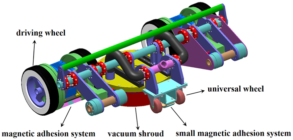
Structure of water-jetting wall-climbing robot.
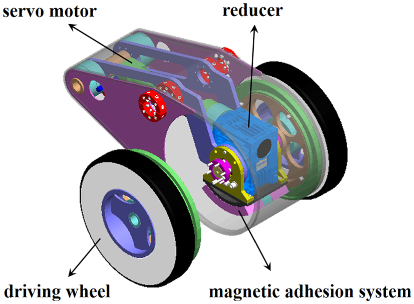
Detailed structure of adhesion-locomotion system.
To determine the value for required adhesive forces, a free body diagram of robot is built on the boundary conditions ensuring that robot operates on the surface without slipping or overturning. As demonstrated by Figure 3, equations (1)–(3) are obtained


Free body diagram of water-jetting wall-climbing robot.
where Ff1 is the sum of friction forces between driving wheels and surface, Ff2 is the sum of friction forces between universal wheels and surface, Ffs is the friction force between vacuum shroud and surface, Fm1 is the sum of adhesive forces from magnetic adhesion systems at driving wheels, Fm2 is the adhesive force from magnetic adhesion system at universal wheels, Fj is the reaction-propulsion force from water jets obtained by equation (4), 20 Fv is the vacuum suction force at vacuum shroud obtained by equation (5), G is the gravitational force acting on the robot, N1 is the sum of support forces at driving wheels, N2 is the sum of support forces at universal wheels, Ns is the support force at vacuum shroud, and β is the inclination angle between surface and vertical direction. To describe clearly, four points are defined in Figure 3. Point A is the contact point between driving wheel and surface, point B is the contact point between universal wheel and surface, point C is the point where Ns acts, and point O is the gravity center of robot. Therefore, three distances along the surface are defined as follows: l1 is the distance between points A and O, l2 is the distance between points A and C, and l3 is the distance between points A and B. And h is the vertical distance from point O to surface

where d is the inner diameter of vacuum shroud, pj is operation pressure of water jet, pv is negative air pressure in the vacuum shroud, and Q is the flow rate of water jet. Here, the above pressures have units of MPa and flow rate have units of L/min.
Given the statically indeterminate problem exiting, equations (6)–(8) are obtained


where μ1 is the static friction coefficient between driving wheel and surface, μ2 is the static friction coefficient between universal wheel and surface, and μs is the static friction coefficient between vacuum shroud and surface.
To simplify the calculation, it is assumed that the above three static friction coefficients have the same values and all are represented by μ. Then, with equations (1), (2) and (4)–(8), equation (9) can be derived and is used to determine the total values of adhesive forces to avoid slip

When the robot is about to overturn, it is known that value of N2 equals zero and value of Ns is very small, which can be seen as zero. According to equation (3), equation (10) is derived and determines the value of adhesive force from magnetic adhesion system at universal wheels to avoid overturn

In practice, when the robot just adsorbs on the surface, the negative suction of vacuum shroud does not work because the air pressure in the vacuum shroud is zero. It requires more adhesive force than operating mode for robot to avoid slip and can be used to determine the values of Fm1 and Fm2 approximately, which actually increases the reliability of design. Then, equations (9) and (10) can yield equations (11) and (12)


Equations (11) and (12) yield

With the help of MATLAB, solutions of equations (12) and (13) can be obtained as illustrated by Figure 4. Here, values of some parameters are listed in Table 1 and the value of β varies from zero to 90°. Clearly, Fm1 has a maximum value of 2503.2 N when β is 26° and Fm2 has a maximum value of 719.5 N when β is 32.09°. Therefore, the design goal of magnetic adhesion systems can be determined: the adhesive force from one magnetic adhesion system at driving wheels should be about 1252 N and the adhesive force from the small magnetic adhesion system at universal wheels should be about 720 N. With the above design goal, design and optimization of magnetic adhesion system can be carried out. Since the two above magnetic adhesion systems have similar structures, only the study of magnetic adhesion system at driving wheels, which is larger and heavier, is involved in the article for brevity. Without special note, the term magnetic adhesion system refers to that mounting at driving wheels in the following.

Adhesive force with respect to inclination angle.
Parameters of wall-climbing robot.

Design of magnetic adhesion system
Figure 5 shows the designed magnetic adhesion system. It includes four pieces of permanent magnets, one aluminum magnetic-flux insulator, and one yoke. The permanent magnets are separated into two groups by the magnetic-flux insulator. As demonstrated in Figure 6, the magnetic-flux insulator forces the magnetic flux flow from one group of permanent magnets, through surface with a ferromagnetic material, to the other group of permanent magnets while not flowing from one group directly into the other group. Moreover, the yoke concentrates most of the magnetic flux into the circuit. This structure makes sure a rather large adhesive force produced.

Structure of magnetic adhesion system.
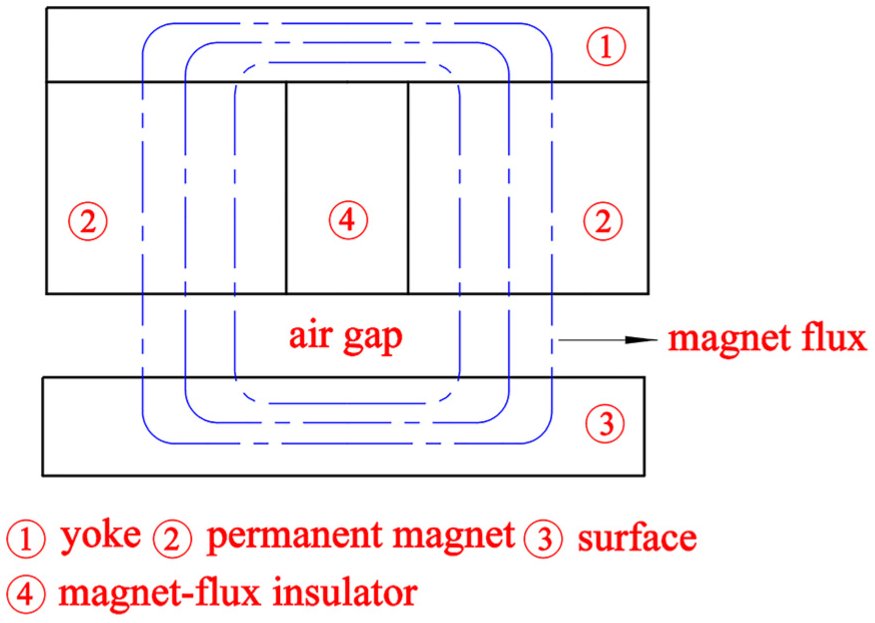
Magnetic flux circuit.
In this part, the aim is to obtain an optimal design of magnetic adhesion system, which could produce an adhesive force of 1252 N to make robot climb on the surface normally with a lightweight magnet. Here, an index γ is introduced to evaluate the performance of magnetic adhesion system, which equals the ratio of adhesive force to mass and is defined by equation (14)

where Fm is the adhesive force and Mm is the mass.
Considering the robot size and the limited assembly space, some dimensions of magnetic adhesion system are defined as demonstrated in Figure 7. There are three dimensions involved in the optimization, which are the thickness of permanent magnet, the width of permanent magnet, and the thickness of yoke, represented by Tm, Wm, and Ty, respectively. Before finding a proper set of the above three dimensions, the magnet layout and magnetizing direction should be determined for increasing the adhesive force.

Dimensions of magnetic adhesion system.
Influence of magnet layout and magnetizing direction
For one magnet, magnetic flux flows from its North Pole to South Pole and completes one circuit. If there are several magnets, their layout and magnetizing directions will influence flux distribution and the resulting magnetic adhesive force. Obviously, analysis of the influence of magnet layout and magnetizing direction on magnetic adhesive force should be done to improve magnetic adhesive force.
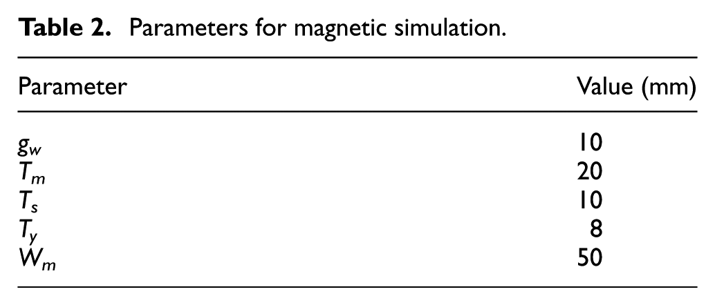
With parameter values listed in Table 2, magnetic flux distributions of two types magnet layouts are obtained by simulation software Ansoft Maxwell, as demonstrated in Figures 8 and 9. Here, gw is the air gap in the working condition (also in the testing condition), and Ts is the thickness of surface. The magnet material of N38 NdFeB is used and its properties are listed in Table 3. The values of the maximum magnetic induction intensity of layout A and B are 1.3065T and 1.8937T, respectively. Obviously, layout B has a more concentrated flux and a stronger magnetic induction intensity, which is a better layout and adopted in the design.
Parameters for magnetic simulation.

Two types of magnet layouts (left: layout A, right: layout B).

Simulation results of magnet flux distribution (left: layout A, right: layout B).
Properties of N38 NdFeB.

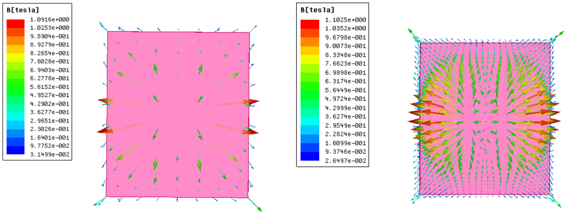
Similarly, magnetizing direction also influence the magnetic flux distribution. Since the magnets have an arc shape, there are usually two magnetizing directions adopted in practice. One is along the radial direction and the other is along the vertical direction, as demonstrated by Figure 10. Figure 11 indicates that vertical magnetizing direction has a significantly more concentrated flux than the radial one. Therefore, the magnets are magnetized along the vertical direction in the design.

Two types of magnetizing directions (left: radial direction, right: vertical direction).
Simulation results of magnet flux distribution (left: radial direction, right: vertical direction).
Influence of dimensions of magnetic adhesion system
It is known that adhesive force is positively associated with dimensions of permanent magnets under the specific magnetic material, air gap, and surface thickness. However, a large permanent magnet has a heavy weight, which requires more adhesive force for making robot climb on the surface normally. Obviously, there should be an optimal set of dimensions of magnetic adhesion system, which could achieve the necessary value of adhesive force and get a light weight at the same time. Based on the determined magnet layout, magnetizing direction and some magnet dimensions mentioned above, influences of Tm, Ty, and Wm on adhesive force and γ are obtained by Ansoft Maxwell, as illustrated in Figures 12–14. To increase adhesive force, the three dimensions increase in the simulation and the other two dimensions remain the same when one target dimension increases. Here, the initial values of Tm, Ty, and Wm are set to 20, 8, and 50 mm, respectively.

Influence of the thickness of permanent magnet.

Influence of the thickness of yoke.
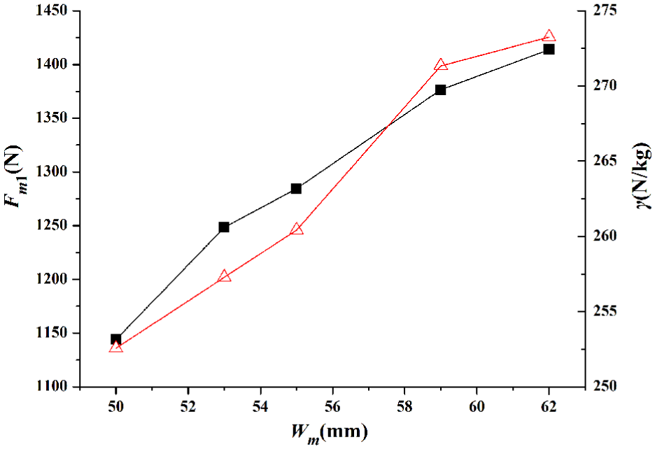
Influence of the width of permanent magnet.
As demonstrated in Figure 12, increasing the width of permanent magnet Tm gets a large γ with increasing adhesive force. When Tm is greater than 30 mm, adhesive force increases gradually, which also happens to γ with a Tm greater than 25 mm. Considering the light-weight and required adhesive force, Tm is set to 30 mm, which gets an adhesive force of 1448 N.
Figure 13 shows that increasing Ty increases adhesive force with a saturation occurring at a value of 18 mm and γ decreasing. It is concluded that a thick yoke gets magnet flux more easily flowing through and then increases the adhesive force. However, the increment of adhesive force is not large enough to gets a smaller γ, which indicates that a too thick yoke has little positive effect while leading to a heavy magnet. Moreover, there is a rather small variation of adhesive force as Ty changing. Therefore, the value of Ty keeps the same and is set to 8 mm.
As demonstrated by Figure 14, increasing Wm is very helpful to increase the adhesive force and γ. However, the total dimension of robot limits the value of Wm. Additionally, the width of magnetic-flux insulator should be large enough to leave the mounting space for bolts. Here, the width of permanent magnet is set to 55 mm, which leads to an adhesive force of 1284.5 N.
Based on the above analysis, the final dimensions of magnetic adhesion system are determined, which have a Tm of 30 mm, a Ty of 8 mm, and a Wm of 55 mm. Then, magnetic adhesion system is manufactured and its adhesive force under different air gaps can be measured by a tension testing machine, which are shown by Figure 15. During the measurements of adhesive force, pieces of A4 paper are inserted into the gap. By measuring the thickness of those pieces of paper, the value of air gap is indirectly obtained. To decrease the error, five tests are carried out and the average value is used. However, there are still unavoidable errors occurred. A peak value of adhesive force exists at 11 mm air gap, which leads to a peak value of ratio of experimental result to simulation result. Here, we ignore the influences of peak value and the two adjacent values.

Results of adhesive force in the simulation and experiment.
Obviously, simulation result is greater than experimental one. For example, an air gap of 10 mm produces an adhesive force of 1445 N in the simulation, while the experimental result is only 1211.7 N. Since the ratios of experimental result to simulation one are in a small range of 0.73–0.77 at air gaps from 1 to 8 mm, which get values of adhesive force greater than 1252 N, it shows a consistency between experimental result and simulation one. Therefore, a correction factor is used to revise the simulation result for guiding the design of magnetic adhesion system in the practice. Here, the value of correction factor is set to 0.75.
Experimental study of adhesion-locomotion system
It is known that tire deflection is a strongly nonlinear process, which is related to many factors, such as tire material, inflation pressure, and temperature. In this part, an experimental method is applied to obtain the performance of tire deflection and no further theoretical study is mentioned, which is not the focus of this article. Then, with the obtained curve of adhesive force, the values of initial air gap and inflation pressure can be determined.
Tire deflection experiment
Before doing the tire deflection experiment, support force at driving wheels N1 should be known, which is used as a reference value to the experiment. As demonstrated by Figure 16, a static structure finite element analysis (FEA) model of the robot is built to estimate the value of N1 by ANSYS Workbench. Here, contact boundary conditions are applied, adhesive forces are simulated by the force loads, and the material of tires is rubber. The value of N1 comes out as 1761.9 N. Then, tests are carried out in the test rig, which are shown in Figure 17(a).
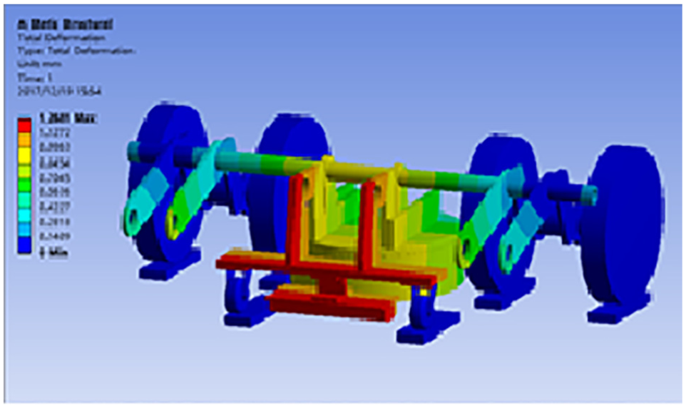
Static structural FEA model of robot.

Experiment of tire deflection: (a) test rig and (b) deflection data.
A connector is designed to connect two driving wheels and to deliver push force from test rig to driving wheels, where the push force is the reacting force of N1. The vertical displacement of the connector is recorded as the deflection of tire. As demonstrated by Figure 17(b), tire deflection curves are obtained under different inflation pressures. Here, there is a peak value at 500 N, which is considered as a measurement error and ignored in the following. Obviously, a high inflation pressure makes the tire hard and has a small tire defection. Clearly, there is an approximate linear relationship between push force and tire deflection.
In fact, a high inflation pressure is good for the robot to weaken the coupling process between tire and magnet. If inflation pressure has an infinite value, which makes the tire rigid with no deflection, the initial air gap is the working air gap and the design magnetic adhesive force is the working magnetic adhesive force. It is easy to determine the assembly parameters of the robot. However, a high inflation pressure also increases the load of tire and decreases its service life, which is prone to blow out. Given consideration about both, an inflation pressure of 3.5 bar is chosen in this article and the fitting equation is obtained based on the data, as illustrated by equation (15). Then, based on FEA result of robot, the corresponding deflection dw can be obtained by substituting a push force of 1761.9 N into equation (15), which is 9.23 mm

where dw is the tire deflection in the working condition and Fpush is the push force which equals the value of N1.
Similarly, a fitting equation is obtained based on experimental data in Figure 15, as illustrated by equation (16). Then, it is known that gw with a value of 8.6 mm can achieve the required magnetic adhesive force of 1252 N

where
To determine the value of initial air gap, Figure 18 is used to demonstrate the relationship between gi and gw. Here, gi is the initial air gap used in the assembly process. As demonstrated in Figure18, the left part is the initial status without tire deflection and the right part is the working status when the magnetic adhesive force and the air pressure of tire come to a balance. Clearly, with the obtained values of dw and gw, the initial air gap gi equals 17.83 mm, which guides the assembly-dimension design between magnetic adhesion system and the robot.

Relationship between the initial air gap and working air gap.
Robot prototype experiment
After determining the initial air gap and inflation pressure, the adhesion-locomotion system is integrated into the robot prototype and the performances are tested on a vertical steel surface in the lab, as demonstrated in Figure 19. Results show that the robot prototype climbs well with a maximum payload of 62.9 kg on the dry surface, which has a weight of 97 kg, an average velocity of 4 m/min and could cross an obstacle with a height of 6 mm. Furthermore, the robot prototype is tested on the surface of ship hull in the shipyard and could strip old paint and rust with a good maneuverability while pulling heavy pipes and hoses. The above tests prove that the design of permanent magnetic wheel-type adhesion-locomotion system is feasible and can meet the requirement of wall-climbing robot with heavy payload capacity.

Robot prototype experiments (left and middle: test in the lab, right: test in the shipyard).
Conclusion
This article has proposed a permanent magnetic wheel-type adhesion-locomotion system for water-jetting wall-climbing robot, which comprises of an annular-sector shaped magnetic adhesion system and a pneumatic tire. This type of adhesion-locomotion system could produce a large adhesive force and a large friction force with a small mass. Meanwhile, the coupling interrelationship between magnetic adhesion system and pneumatic tire brings difficulty to determine the values of initial air gap and inflation pressure, which is important for adhesion-locomotion system normally operating in the robot. Combining simulations and experiments, dimension optimization of magnetic component and determination of values of initial air gap and inflation pressure are completed. According to the tests in the lab, the adhesion-locomotion system makes robot prototype climb well with a maximum payload of 62.9 kg, an average velocity of 4 m/min, and an obstacle-crossing capability 6 mm on the surface. Finally, robot prototype is tested in the shipyard, which proves the design of adhesion-locomotion system feasible.
Footnotes
Handling Editor: Xianzhi Zhang
Declaration of conflicting interests
The author(s) declared no potential conflicts of interest with respect to the research, authorship, and/or publication of this article.
Funding
The author(s) disclosed receipt of the following financial support for the research, authorship, and/or publication of this article: This research was supported by the Fundamental Research Funds for the Central Universities (Grant No. 2017XZZX001-02A) and the Scientific and Technology Cooperation Project of Zhoushan City and Zhejiang University (Grant No. 2017C8221).