
Abstract
The development of underwater vehicles is facing the problem of sustainable energy supply. This study introduces a small water turbine, the Lenz turbine, for energy generation from the ocean currents which will provide energy for the underwater vehicles. Computational fluid dynamics simulations of the effect of geometric parameters, including the blade radius, chord length, and pitch angle, on the performance of the turbine are conducted. The Reynolds-Averaged Navier–Stokes equations are numerically solved with a sliding mesh method. Thirteen sets of tests in total are performed at different values of tip-speed ratios. The tests are divided into three groups to study the effect of the three parameters mentioned above, separately. The obtained power coefficients, coefficient of torque, and the dynamic torque on a blade are then compared in each group of tests. Pressure contours and velocity contours are given to explain the reason how the geometric parameters affect the rotor performance.
Introduction
Rapid development in the field of robotics has created a plethora of applications which have wider implications for our society. Among the various kinds of robotics, underwater vehicles are a kind of self-propelled, self-executing underwater robots, which play an important role in expanding people’s knowledge of the ocean. Autonomous underwater vehicles are capable of a wide range of applications,1–3 such as pipeline inspection, 4 underwater search and rescue, mine-sweeping, 5 and oceanographic exploration.6,7
Underwater working time is an important indicator of the performance of underwater vehicles. Therefore, low power consumption techniques must be considered in the design process of underwater vehicles, such as node circuit design, communication design, and measuring instruments design. However, present underwater vehicles are powered by the on-board batteries; due to the size of the hull volume and the weight restrictions, the total energy of an underwater vehicle is limited. In order to improve the working time of underwater vehicles, the energy supply problem must be solved.
Nowadays, renewable energy is getting more and more attention, for example, the ocean current energy. The total global ocean current is estimated at about 5000 GW, which gave a potential countermeasure to environmental pollution and energy crisis. 8 Underwater vehicles are always deployed where ocean currents exist. The kinetic energy stored in ocean currents provides an ideal alternative to recharge the underwater vehicles. Previous studies have studied the feasibility of using solar energy to power a sensor network. 9 Therefore, it has the hope of extracting energy from the environment and providing power for underwater vehicles.
Water turbines are used to convert the kinetic energy stored in ocean currents into electricity. According to the angle between the axis of the rotor and the flow direction, we can divide the existing turbines into two categories: horizontal axis water turbines (HAWTs) and vertical axis water turbines (VAWTs). HAWTs have their rotor axes parallel to the current direction, while the axes of the VAWTs are perpendicular to the flow direction. HAWTs are usually of mid-to-large size; therefore, they are very picky about the locations despite the high efficiency. Besides, HAWTs require sustained flow velocities to efficiently generate power; 10 the change of velocity, direction, and turbulence intensity would decrease the performance of the turbines. VAWTs are usually designed into small-scale structures and have the advantage of generating power under poor flow conditions, such as low velocity and erratic flow directions.11,12
Darrieus turbine is the most efficient type of VAWTs. There are several straight airfoils to make lift and drive the rotor. A great deal of research has been done on the dynamic model of Darrieus turbine.13–15 People have used extensive computational fluid dynamics (CFD) and experimental methods to optimize the performance of Darrieus turbine.16,17 Methods to increase cranking torque and efficiency often employ pitch control mechanisms and torque blades. And the rocking of the Darrieus turbine is inferred. 18
A Savonius turbine consisting of two or three curved blades is a VAWT. The comparison of the Savonius turbine with the Darrieus turbine shows that the former has higher starting torque, better starting performance, and ability to operate under complicated turbulence and the latter has a higher efficiency.19–21 Comprehensive studies have been done to examine the effects of the rotor aspect ratio, the overlap, the number of buckets, the rotor endplates, and the influence of bucket stacking on the performance of the turbine.22–26 Moreover, some researchers found that changing the structure of the turbine can improve the performance of the Savonius turbine. Kamoji et al. 27 studied the aerodynamic characteristics of an improved Savonius turbine with propeller. Golecha et al. 28 studied the effect of the upstream guide vane, which can affect the deflection of the return vanes on the performance of the turbine. Except for the Darrieus and Savonius turbines, some other types of VAWTs have also been presented in existing literatures, including the Zephyr turbine 29 and Giromill turbine. 30
As a foot stone for the future development of the underwater power generation networks, this article aims to numerically model a novel type of VAWT, the Lenz turbine invented by Lenz, and study its hydrodynamic behavior. The Lenz turbine is designed with three J-type blades (see Figure 1). This turbine is expected to operate at low velocities and turbulent flow patterns and would be an ideal choice for small-scale power generation. However, there have been less relevant studies on this turbine so far. S Sivamani et al. 31 tested a three-bladed two-stage LENZ-type vertical axis wind turbine in an open environment condition and provided reliable experimental data to help in the next design optimization. J Zwierzchowski et al. 32 described the construction and operating principle of a turbine. The power performances, mechanisms of torque generation, and the effect of design parameters need to be studied. In this article, with the aim of providing a better understanding of the above issues, comprehensive CFD simulations were performed by solving numerically the incompressible Navier–Stokes equations with a sliding mesh method. Three geometrical parameters of the blade, including the pitch angle, the chord length, and the radius of the leading edge, were considered.

Two-dimensional schematic of a Lenz turbine.
Parameter definition
Figure 1 is the two-dimensional schematic of a Lenz turbine, where the flow velocity is represented by U, the azimuth angle of the blade is represented by θ, and the angular velocity of the turbine is represented by ω. The geometric parameters include the rotor radius R, the blade preset pitch angle
In this study, the rotor radius is equal to 0.9 m. Lenz had proposed a set of specific values for the parameters from experience (case 1 in Table 1); however, little information on the principle which decided the value was given. Changing the parameters in each direction away from the recommend value separately (cases 2–13 in Table 1) is for a better understanding of the influence of the geometric parameters,
Main structural parameters of the tested models.

Numerical method
In this study, the choice of two-dimensional CFD simulation was mainly due to the fact that the turbine blades had the same cross section in the transverse direction and the span effect was negligible. Rotor and the relative rotational motion of the magnetic field can be achieved using a sliding mesh model.
Computational domains and boundary settings
Rectangular computing domain can produce the full development of traffic and reduce the impact of congestion. Rectangular domain here is
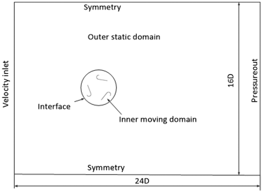
Computational domains and boundary settings.
The entire domain is composed of two sub-domains, an outer static domain and an inner domain. Internal rotation domain contains the rotor and rotates with a rotor angular velocity ω.
There was a uniform and steady velocity profile (1 m/s) at the inlet of the computation domain and a pressure outlet boundary at the outlet of the domain. On the top and the bottom edges of the domain we can use the symmetry boundary conditions. To avoid the wall effect, symmetrical boundary conditions were used because it can allow the solver to consider the wall as part of a larger domain. We apply the no sliding boundary conditions on the blade surface. A sliding interface which allows the flow properties to be transferred exists between the outer fixed field and the inner rotating field.
Grid generation
We use the MESH tool in ANSYS 13.0 to generate a computational domain grid (see Figure 3). To accurately describe the boundary layer flow, boundary layer elements are applied to the blade profile. The Reynolds number was calculated from the flow rate and the chord of the blade, and the value obtained is about

Computational grid: (a) grid near internal rotational domain and (b) boundary layers.
Turbulence model and solution sets
The shear stress transport (SST)

Five revolutions per simulation are required to achieve convergence results. The result of the final revolution was used for analysis. The 1°/step was set as a time step, that is, the rotor turned 1° at every time step. The magnitude of the residuals determined the convergence. All of the following scaling residuals which were below
Numerical method verification and validation
The effect of mesh density on the individual blade torque can be evaluated by the grid convergence studies. With a tip-speed ratio of 0.5, the simulation of case 1 was performed. Figure 4 shows the calculated torque coefficient on the blade for four grids with approximately 48,000, 57,000, 78,000, and 106,000 elements, respectively.

Torque coefficient of the blades for grid convergence.
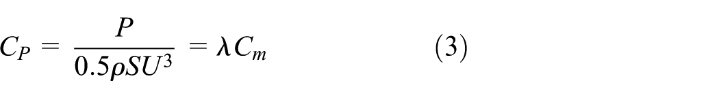
The following formula defined the torque factor

where the torque acting on the blade is represented by M and the cross-sectional area is represented by S. S satisfies the relationship
Due to the similar shape of the Lenz rotor, a single-stage Savonius rotor was used for validation studies. The measured rotor diameter was 1 m, the height was 1 m, the blade radius was 0.25 m, the overlap ratio was 0.1, and the flow speed was 1 m/s. The experimental data were presented by Blackwell et al.
35
Figure 5 shows the calculated rotor average torque coefficient. We can see that the simulation results agreed well with the experiment data, especially when

Results of the numerical method validation.
Results and discussion
Influence of the preset pitch angle on the performance of the rotor
Cases 1 and 2–5 are tested to study the influence of the blade preset pitch angle on the rotor performance. In Figure 6(a) and (b), the coefficients of the averaged torque and power of the rotor with respect to
where the generated power is represented by P. It was shown in Figure 6(a) that the averaged torque decreases with an increase in

Simulation results of the rotor with different preset pitch angles: (a) coefficient of averaged torque and (b) coefficient of averaged power.
Figure 6(b) shows that the power curve first rises and then drops down as
The dynamic torque on a single blade with different pitch angles for a rotation cycle at

The dynamic torque coefficient of a single blade with different pitch angles at

Pressure contours of the rotor with different pitch angles: (a)
The blade torque curves in Figure 8 reach their peak values around
Pressure contours of the rotor with different pitch angles: (a)
Influence of the blade chord length on the rotor performance
It is possible to obtain the effect of blade chord length on rotor performance using cases 1 and 6–9. The coefficients of average torque and power for rotors with different blade chords can be seen in Figure 10(a) and (b). The averaged torque decreases with an increase in
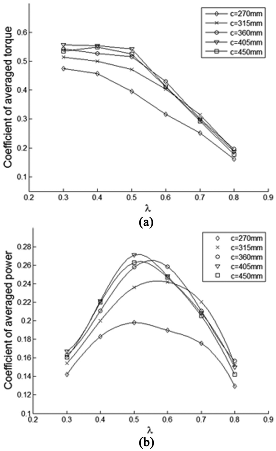
Simulation results of the rotor with different blade chord lengths: (a) coefficient of averaged torque and (b) coefficient of averaged power.
The dynamic torque on a single blade with different chord lengths for a rotation cycle at
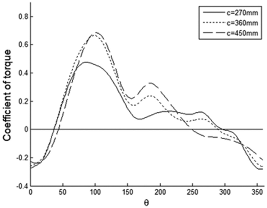
The dynamic torque coefficient of a single blade with different chord lengths at

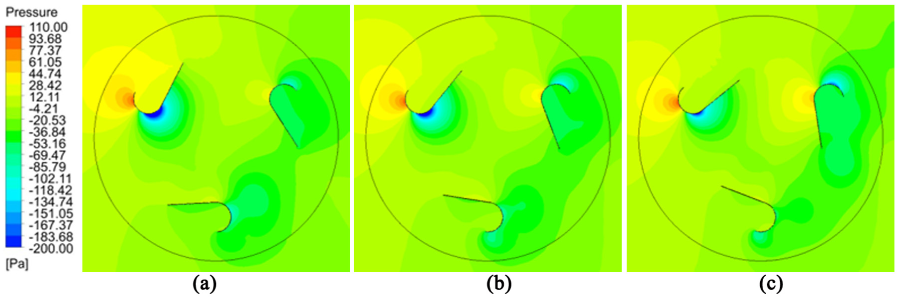
Pressure contours of the rotor with different blade chord lengths: (a)
It can also be seen in Figure 11 that the blade with larger chord length has a wider negative torque terrain. For example, the torque on the blade of
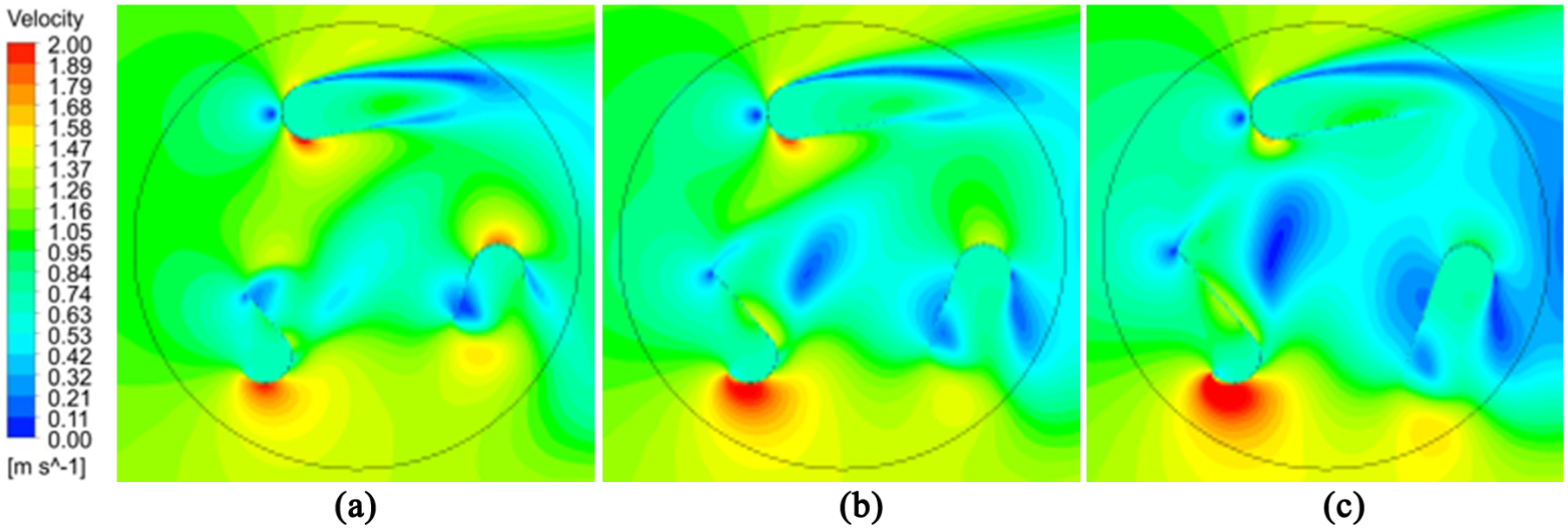
Velocity contours of the rotor with different blade chord lengths: (a)
Influence of the blade radius on the rotor performance
Cases 1 and 10–13 are tested to investigate the effect of the blade radius on the rotor performance. The coefficients of average torque and power for rotors with different blade radii can be seen in Figure 14(a) and (b). The averaged torque decreases with an increase in
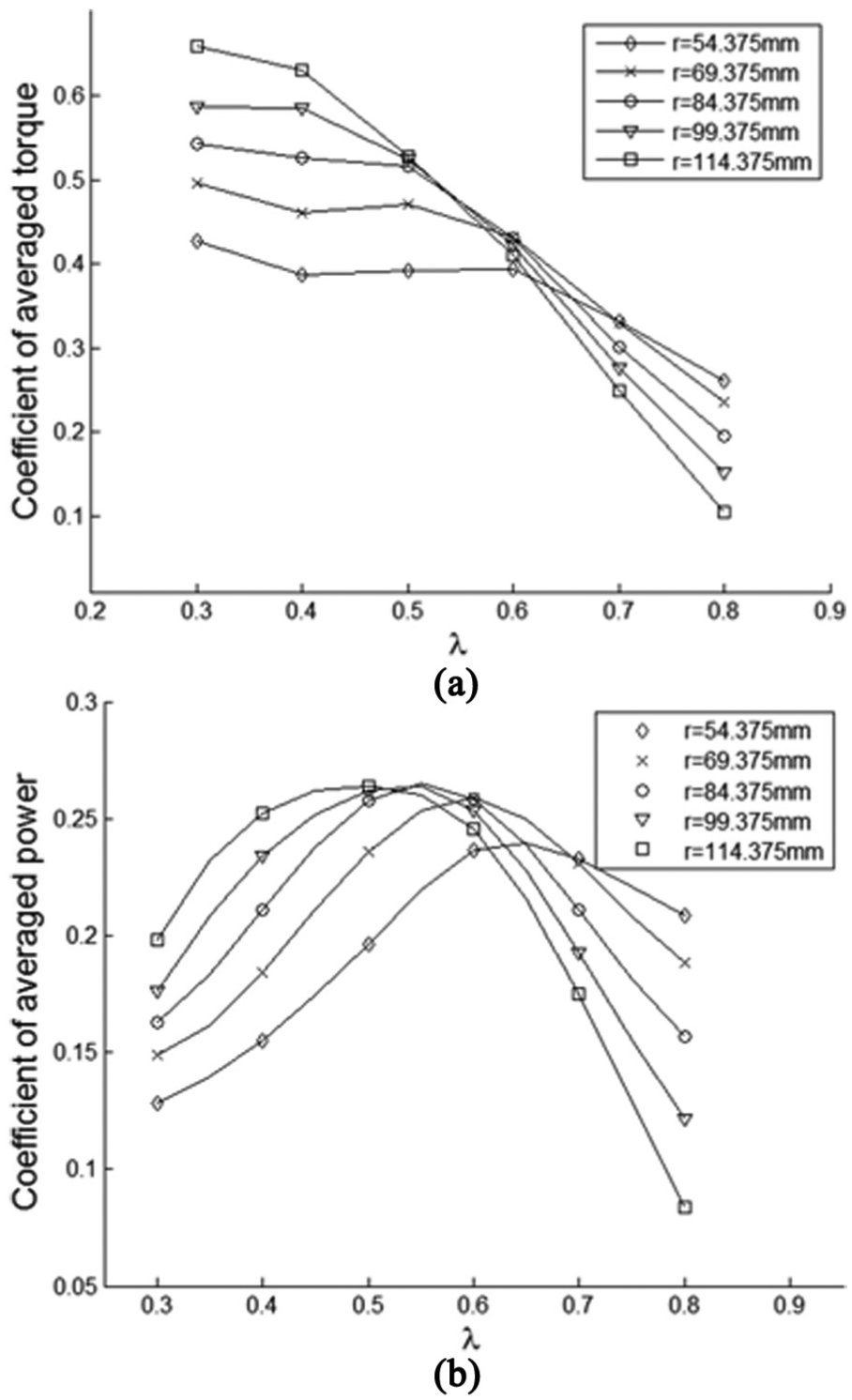
Simulation results of the rotor with different blade radii: (a) coefficient of averaged torque and (b) coefficient of averaged power.
The dynamic torque on a single blade with different blade radii for a rotation cycle at
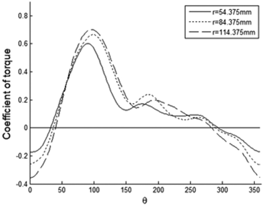
The dynamic torque coefficient of a single blade with different blade radii at
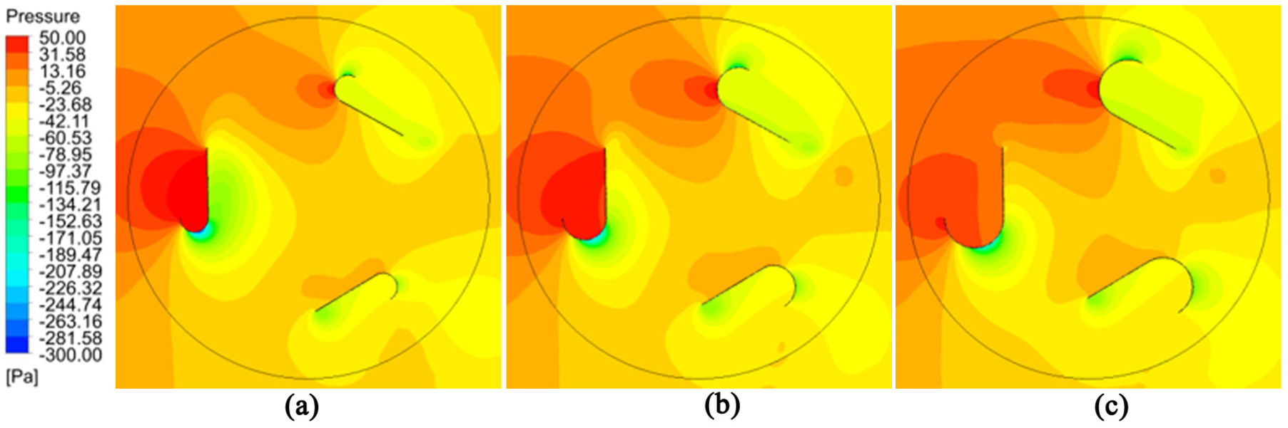
Pressure contours of the rotor with different blade radii: (a)
Conclusion
This article presented the CFD simulations of a novel type of VAWT, the Lenz turbine. Due to less research on this type of turbine, the conclusions drawn by this article have made a great contribution to the design optimization and other aspects. The effect of three design parameters—preset pitch angle, blade chord, and radius on the performance of turbine—was researched. Each parameter has the following influences on the performance of turbine:
The optimal pitch angle for the maximum output power should be in the range of
The rotor with a blade chord length of 405 mm generates the highest power coefficient, 0.2710, at
The leading edge radius has a small effect on the peak power when
In future work, we can improve turbine performance in three directions based on the conclusions obtained in this article and provide a strong basis for future design.
Footnotes
Handling Editor: Guang Li
Declaration of conflicting interests
The author(s) declared no potential conflicts of interest with respect to the research, authorship, and/or publication of this article.
Funding
The author(s) disclosed receipt of the following financial support for the research, authorship, and/or publication of this article: This study was supported by the National Science Foundation of China (Grant No. 51179159, 61572404) and the Shaanxi Province Youth Science and Technology New Star Project (Grant No.2016KJXX-57).