
Abstract
In this article, an autonomous robotic fish is designed for underwater operations like object detection and tracking along with collision avoidance. The computer-aided design model for prototype robotic fish is designed using the Solid Works® software to export an stereolithography (STL) file to MakerBot, a 3D printer, to manufacture the parts of robotic fish using polylactic acid thermoplastic polymer. The precise maneuverability of the robotic fish is achieved by the propulsion of a caudal fin. The oscillation of the caudal fin is controlled by a servomotor. A combination of visual and ultrasonic sensors is used to track the position and distance of the desired object with respect to the fish and also to avoid the obstacles. The robotic fish has the ability to detect an object up to a distance of 90 cm at normal exposure conditions. A computational fluid dynamics analysis is conducted to analyze the fluid hydrodynamics (flow rate of water and pressure) around the hull of a robotic fish and the drag force acting on it. A series of experimental results have shown the effectiveness of the designed underwater robotic fish.
Introduction
In recent years, bioinspired underwater vehicles have become a significantly hot research topic in the field of ocean engineering. Especially, fish-like robots have attracted the attention of the research community because of its great advantages over conventional propeller-driven underwater robots, such as high efficiency, extreme swiftness, and station-holding ability. 1 Furthermore, fish robots have shown better performance in terms of swimming mechanism. 2 Such kinds of robots have a wide range of underwater applications and have various other applications rather than deep-sea scientific exploration, military, advertisement, and entertainment.
As the name suggests, the fish robots are inspired by real fish and are supposed to mimic the behavior of a fish in terms of maneuverability in shallow waters. Therefore, the motion of the fish robot is indeed based on various features of a real fish. Thanks to the advancements in technology, the fish robot has a more advanced feature in terms of speed, sensing, and intelligence as compared to real sea creatures. For instance, due to advanced vision technology, now underwater robots have a better ability to identify the targets and obstacles in the aquatic environment. 3,4
The design and development of underwater robots consist of vital hardware and software components, such as sensors, actuators, and microprocessors along with a control mechanism developed using control theory. The locomotion of the fish robot is mainly classified into three categories known as carangiform, anguilliform, and thunniform, respectively, (i) by waving the posterior body, (ii) by waving the entire body, (iii) and undulation by caudal fin only. Various models of fish robots have been proposed in the literature. For instance, in literature, 5 researchers have developed a biomimetic fish robot prototype with carangiform locomotion. The robot possesses a pair of pectoral fins and a caudal fin actuated by direct current (DC) motors. A multi-link fish robot prototype with anguilliform locomotion has been designed in which both forward and backward movements are controlled with three servomotors used as actuators in literature. 6 A self-correcting mechanism has been adopted in literature 7 to acquire the maneuverability of the boxfish. The fish robot mimics the ostraciiform locomotion by using pectoral fins and caudal fin actuated by servomotors. Hu et al. 8 presented a biomimetic fish robot that has the locomotion of type thunniform. Experimental results have been obtained to analyze the swimming speed and maneuverability by the rotational motion of the caudal fin. Similarly, Yu et al. 9 successfully designed a radio-controlled fish robot having a flexible body and a rubber caudal fin for an underwater robot competition.
Mohan et al. 10 designed a fish robot “Meta-KOI” inspired by Koi fish. The fish robot has a polycarbonate spine with skeletal discs and servomotor for caudal fin actuation. Similarly, Ay et al. 11 developed a carangiform locomotion-based two linked radio control (RC) servomotors “i-RoF” prototype robotic fish. The authors of literature studeis 12,13 have developed a small-scale fish robot based on the magnetic actuator.
To attain better and efficient maneuverability of the fish robot, it is necessary to have information about various parameters of the fluid in which the fish robot is swimming. These parameters include fluid flow and pressure that the fluid exerts on the fish robot. Computational fluid dynamics (CFD) designed tool is widely used to predict fluid flow in different domains. It also measures the drag force faced by the fish robot when moving in the fluid. Besides, it also plays a vital role to test the prototype model prior to the actual design created. 14,15 In literature, 16 CFD simulation has been conducted to analyze the distribution of hydrodynamics values (velocity and pressure) around the biomimetic fish robot to address the flaws of the robotic fish model.
A number of underwater robot applications involve object/target detection and tracking. The object can be detected through various kinds of sensors such as sonar, infrared, or vision-based sensors. Vision-based sensors are more advantageous over other sensors as the information they provide is more diverse. This information includes the size, color, and shape of the target object. The first vision-based object tracking fish robot is developed by Hu et al. 17 A simple complementary metal-oxide-semiconductor (CMOS) camera has been used to obtain the images and the quality of images has been improved through Camshift image processing algorithm. Meng et al. 18 developed an underwater drone supported by a panoramic camera and have presented the object detection algorithm based on convolution neural networks. Zheng et al. 19 presented a vision-based biomimetic fish robot, with the on-board camera to gather visual information of surrounding to play water polo-like games. The authors of literature 20 developed a visualized fish robot to navigate in the underwater environment with the aid of several visual sensing algorithms.
Furthermore, path following and collision avoidance strategies have been studied by various researchers for marine vehicles. Liang et al. 21 designed a robust controller using a fuzzy logic algorithm by incorporating the popular backstepping and sliding mode (FBSM). In fact, the 3D path following errors can be made arbitrarily small for an underactuated vehicle. The resulting FBSM controller provides a global solution to address the uncertainties and environmental disturbances. The novel adaptive fuzzy-dynamic surface control (AF-DSC) scheme has been reported in literature 22 to identify the underactuated marine vehicles tracking errors due to uncertainties and ocean disturbances while 3D path following. Therefore, developing the AF-DSC scheme proved the key research to overcome the errors related to the conventional backstepping technique for the 3D path following control of the underactuated vehicles. Similarly, the ability of underactuated autonomous underwater vehicles (AUVs) for collision-free path planning is necessary for numerous real-time applications underwater. Studies have been reported in literature, 23 –25 where the problems of path planning and collision avoidance for multiple underactuated vehicles are discussed in detail and swarm control strategy and artificial potential field are derived, respectively.
The use of the camera to add vision ability in fish robot has a few disadvantages as well. For instance, a CMOS camera takes the images, only. Image processing algorithms are required to extract desired information from the images, thus requires more computational complexity and resources. 26 The problem of huge data processing can be resolved by using Pixy vision sensors. Pixy, in fact, uses a color-based filtering algorithm and is capable of processing an entire 640 × 400 image frame in every 1/50th of a second. Moreover, Pixy’s filtering parameter is dominant in changing the lighting and exposure and is significantly better than other vision sensors. 27,28
In this article, we have designed and developed a low-cost embedded vision-based, autonomous robotic fish to detect and follow an underwater target. The developed robotic fish is capable of recognizing the object of interest and drive toward it using a Pixy vision sensor. The contributions of this work include a prototype design of robotic fish that has a rigid cylindrical shaped hull from the middle while the head has a conical shape with a round nose to cope with the problem of drag force. In addition, a low aspect ratio (AR) caudal fin is designed to achieve better locomotion while diving. Moreover, ANSYS Fluent 16.0 software is used to investigate the hydrodynamics of the hull design of the robotic fish. The drag coefficient has been calculated through the observation of the fluid flow across the body of the hull. To achieve a precise driven mechanism, a thunniform locomotion model is adopted. It could be inferred that the lateral motion is mostly in the caudal fin and the caudal peduncle (the region connecting the caudal fin). Simple closed-loop control is designed to achieve precise control of the oscillatory movement of the caudal fin. Furthermore, to track the target of interest underwater, a vision sensor named Pixy CMUcam5 which has a hue and saturation based algorithm is used to recognize the color and size of the target. Compared with other vision sensors that process a huge amount of visual information, hence requires more computational power, the Pixy vision sensor sends the data of the desired target to the microcontroller for further computations. These data include the target’s color and position in terms of x- and y-coordinates along with height and width. The ultrasonic sensor provides the distance from the obstacle. Finally, to demonstrate the effectiveness of the proposed model, object detection and tracking experiments in which the robotic fish tracks the underwater target object were executed in the Testing Lab of Marine Robot (TMR Lab), Ocean College, Zhejiang University.
The rest of this article is organized as follows. The second section describes the mechanical and electrical design of the fish while computational fluid dynamics (CDF) simulations are discussed in the third section. The fourth section addresses the autonomous control and experimental results along the discussion are provided in the fifth section. Finally, we conclude the article in the sixth section.
Robotic fish design
This section presents the design of the robotic fish in the sense of the mechatronic system. This system is integrated with mechanical, electrical, and locomotion control. The design prototype of the robotic fish has been expressed in the subsections below.
Mechanical design
The mechanical design of the robotic fish is divided into two parts: (i) hull and (ii) caudal or tail fin. The fundamental structure of the robotic fish body is a compact, waterproof hull. First, the 3D model of the fish is designed using computer-aided design (CAD) software SolidWorks 2016. The hull is cylindrical from the middle while the head has a conical shape with a round nose to reduce the drag force. The assembled CAD model is shown in Figure 1. The mass property analysis has been carried out to find the physical properties of the designed structure. The volume, mass, and length of the robotic fish are 32.53 in 3 , 0.56 kg, and 415 mm, respectively. The choice of material for the fabrication of the robotic fish is a critical part of this research work as the material should exhibit various properties for the effective underwater operation. In the current design, high-density polylactic acid thermoplastic polymer has been used to make the body of a fish by a 3D printer. The benefits of using this type of material are high strength, handiness, and durability. 29 To make the front and a rear section of the hull waterproof, a layer of epoxy glue applied inner as well as the outer side of both sections of the hull. The waterproof hull protects all internal power and provides housing for electronic components, sensors, and all the weights. The extra weights are necessary to achieve a neutral buoyant so that the fish can swim beneath the water surface

Assembled CAD model of robotic fish. CAD: computer-aided design.
Electronic design
The robotic fish is intended to be used as an autonomous operation. Therefore, it is endowed with onboard power, microprocessor, vision sensor, ultrasonic sensor, wireless HD camera, and Bluetooth module for external interfaces. The robotic fish is actuated by an electric servomotor which screws at the back of robotic fish between the rear body and caudal peduncle of a caudal fin. A vision-based sensor is mounted inside the mouth place with a translucent hemisphere of 50 mm glued to the hull with O-ring between them for waterproof purpose. At the bottom of the hull, a waterproof ultrasonic sensor is placed inside a hollow box.
Three cells (3-S) pack LiPo battery of 5000 mAh capacity provides the power for almost 1 h depending on the fish speed and the load conditions. The battery is charged through iMAX B6 digital Lipo battery balance charger. The three cells (3-S) pack can be fully charged in nearly 2 h. The main control unit of the robotic fish consists of an Arduino Nano ATmega 328 microcontroller. It is a 16 MHz microcontroller with an extensive variety of peripherals from SparkFun Electronics. Pixy CMUcam5 is fixed to the inner side of the fish body for object detection and identification of different signatures (colors) of the object. The image sensor comes with the distinct feature of identifying seven signatures simultaneously. The Arduino receives data from the image sensor through the gray ribbon cable with In-Circuit Serial Programming header. The transmission speed of Pixy is 1 Mbit/s and the information is sent in blocks. The block, in fact, contains various information such as Cartesian coordinates of the targeted object with reference to the sensor’s position along with its height and width. The microcontroller performs decision-making based on the received information and generates pulse width modulation signal to control the propulsion of the caudal fin.
Obstacle avoidance plays a vital role in this project. For this purpose, a low-cost waterproof ultrasonic sensor is the best available option in a market nowadays. When an obstacle comes within a programmed distance, the robotic fish will turn to the user-defined direction. The control framework of the autonomous robotic fish is illustrated in Figure 2 while the important technical parameters are presented in Table 1.

Control architecture system of the autonomous robotic fish.
Parameters of autonomous robotic fish.

ICSP: In-Circuit Serial Programming.
Propulsion mechanism
As mentioned above, the underwater locomotion is achieved through a servomotor. Hitech HS-646WP servomotor from Blue Robotics has been selected for this purpose, and it comes with a distinct waterproof feature. The range of angular rotation of the caudal fin is limited to ±180°. The motivation toward the propulsion mechanism design is picked from various studies regarding the structure of fish. Different species of fish have various swimming models. After a comprehensive study, the propulsion model of Tuna is adopted. This infers that the lateral motion is mostly in the caudal fin and the caudal peduncle (the region connecting the caudal fin). The robotic fish has three degrees of freedom (DOFs), all of which are linked to the caudal fin. Simple closed-loop control is designed to achieve precise control of the oscillatory movement of the caudal fin. The shape of the caudal fin is a rounded square with a low AR, able to produce an adequate thrust force to the robotic fish to conduct better locomotion. The AR has significant importance in the calibration of caudal fin shape. 30
The definition of AR is presented in the following equation
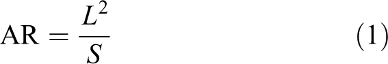
where L is the span length and S is the area of the caudal fin of the robotic fish.
By actuating the caudal fin in an appropriate manner, the maneuverability of the robotic fish in forward, left, and right directions has been achieved. In order to acquire a certain depth, the robotic fish should adequately be neutral buoyant at the desired depth as mentioned above. The installation of the material at the inner side of the hull allows the robotic fish to persist staidly in shallow water. The material selected to attain neutral buoyancy is Fe adhesive wheel weights, as it is a material with high strength and high density. To calculate the buoyant force F
B first, multiply the volume V
W and the density of the fluid


Meanwhile, the pectoral fins are immovable and have to be kept parallel to the horizontal plane to attain stability of the robotic fish while diving. Hence, the maneuverability of the robotic fish is restricted to the horizontal plane.
CFD analysis
The hydrodynamics characteristics, such as velocity and pressure around the hull of the robotic fish, have been analyzed through CFD simulations. It also provides the drag coefficient for the robotic fish. Figure 3 shows the computational domain of a hull of the robotic fish. The value of inlet water flow velocity along the x-axis is chosen as 0.5 m/s. The boundary conditions under consideration include velocity inlet, pressure outlet, and stationary wall. In fact, both sides and the top surface of the water tank wall are interpreted as symmetric wall while the bottom surface represents a wall.

Computational domain of the hull of a robotic fish.
Drag coefficient
Drag coefficient (C
d) dictates the value of the drag force causing resistance comparative to the motion of any object moving with respect to a surrounding fluid. The drag coefficient solely depends on the shape of the body. Figure 4 shows the value of the drag coefficient corresponding to the number of iterations. It is clear from the figure that the drag coefficient of the hull of the robotic fish is 0.18 once the convergence is achieved. This analysis reveals that the hull of a robotic fish easily moves through the surrounding of water with a minimum level of resistance. By using CFD, the estimated drag force recorded is 0.5865 N. The drag force F
d is expressed by the following equation

C d versus the number of iterations.
where the drag coefficient is C d, the density of the fluid is ρ, frontal area of the hull is A f, and water flow velocity is V.
Vector velocity
Fluid flow fluent provides excellent visualization of the flow simulation around the body with the aid of vector velocity. Figure 5 shows the vector velocity around the hull. It is obvious from the figure that the water flow is decreasing (blue pixels) as it approaches the nose of a hull. Then water flow increases away from the nose position to the top surface. The red pixels indicate the highest water flow velocity and can be spotted at the top edge. The maximum water flow velocity recorded is 0.867 m/s. The water accelerated from the hull nose position to the top surface is because of the difference in the pressure. High pressure is recorded when the water stagnates the front area of the hull and it moves toward the lower pressure area which is at the top surface.
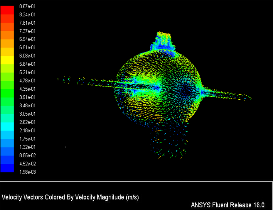
Vector of velocity magnitude.
Static pressure
The result of static pressure contour is shown in Figure 6. It is obvious from the figure that there is a higher pressure concentration at the front section of the hull. The water flow slows down when it approaches the front area of the hull and results in water accumulation into a smaller space. Once the water stagnates at the frontal area of the hull, it transfers to lower pressure areas such as the edges of the pectoral fins, around the nose, and sides and bottom of the hull. When the water flows over the pectoral fins, the pressure decreases (green region).

Pressure contour on the hull of a robotic fish.
However, the pressure continuously decreases moving away from the nose toward mid-section (light green region) of the fish. The pressure becomes high again at the hinges for the camera at the top of the body which is represented as a red region. The pressure again decreases moving toward the rear section of the fish. The maximum pressure recorded is 136.950 Pa at the region where the water stagnates while the minimum is −274.544 Pa.
Control strategy
For the autonomous underwater operation, the robotic fish must be capable of detecting hurdles in the path promptly, make a quick and satisfactory decision, and adopt a suitable path to bypass these hurdles and to get precise navigation. 31,32 The object is detected through a vision-based Pixy CMUcam5 sensor along with the ultrasonic sensor. The image sensor provides the object information like its color and size while the ultrasonic sensor is used to get the information related to the distance between the object and the fish. 33 Based on this information, the robotic fish is able to manage and keep a particular distance from the desired object while tracking it. The primary pattern of the programming which includes decision-making for robotic fish while identifying and tracking the object is shown as an algorithmic flow diagram in Figure 7. To verify the algorithm, a simplified effort is made for the robotic fish to find a dummy object (a red toy fish) based on the hue and saturation algorithm of the image.
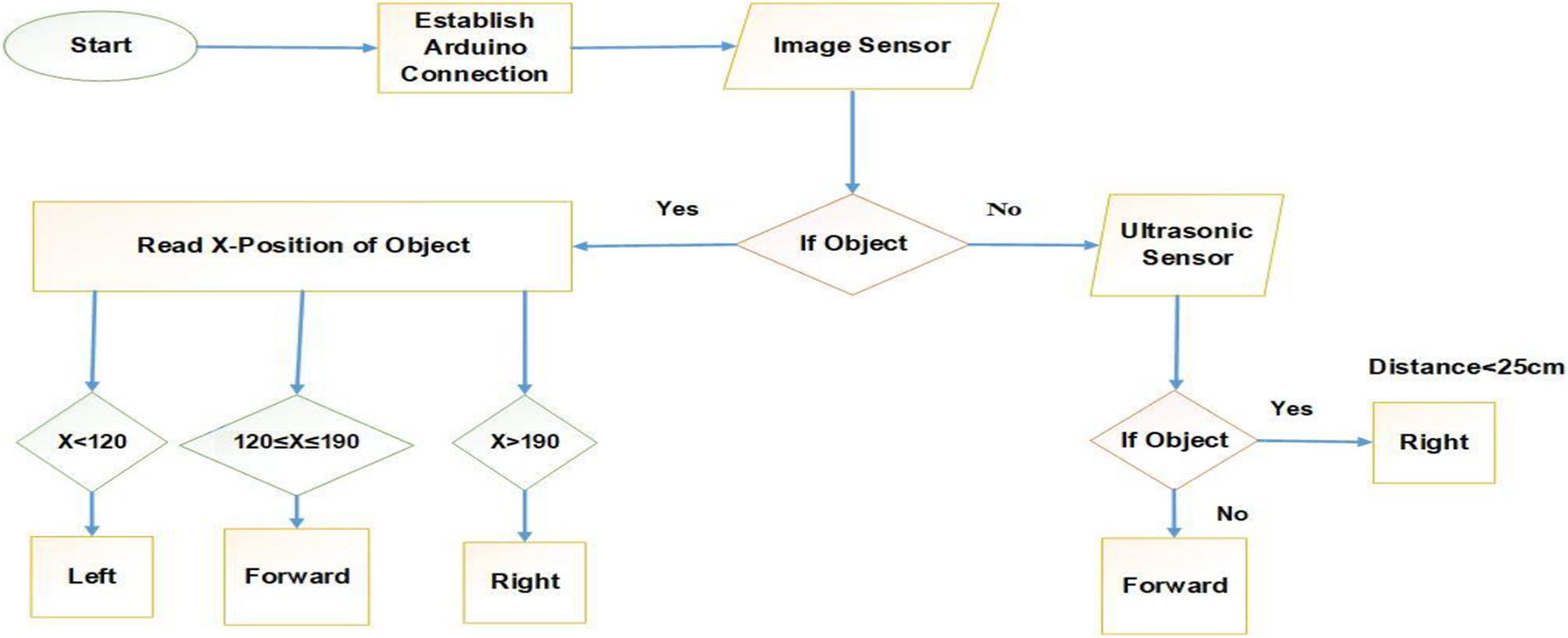
Flow chart of object tracking algorithm.
If there is no object, the ultrasonic sensor will work and robotic fish will move forward; if any other object comes in front of the ultrasonic sensor, it will bypass it and robotic fish changes its direction to the right. If the desired object comes in front, then the position of robotic fish will be changed according to the information as the x-position of the object which is getting from an image sensor having a hue and saturation-based algorithm to recognize the color and size (block) of the dummy object.
Experimental results
The primary water test of the robotic fish has been conducted in the laboratory by using an experimental water tank.
The robotic fish can be controlled instantly by activating the wireless remote control relay. Initially, a simple test has been carried out to examine the visual sensor Pixy CMUcam5 capability of detecting the objects inside water. Figure 8(a) shows that the sensor has detected the various objects of various sizes and colors placed underwater. The sensor is then taught about the specific desired object. In our case, the desired object is a red color golf-sized ball. The visual sensor sends back the data of the desired object, which includes its color, position in terms of x- and y-coordinates along with height and width. Arduino plotter is then used to plot the received data. Figure 8(b) shows the taught desired object while Figure 8(c) depicts the plot of the received data.
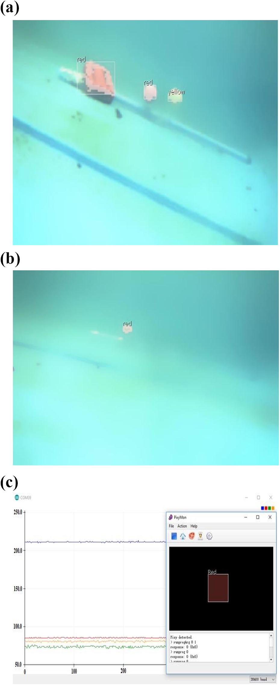
Object detection underwater: (a) distinct objects, (b) defined object, and (c) X- and Y-coordinates along the width and height of the object.
The Bluetooth connection provides a wireless network throughout the operation between the fish and the central platform. PixyMon software displays the image when it is detected by the sensor.
The range of the x- and y-positions of the center of the object in the image is from 0 to 319 and 0 to 199, respectively. 26 If the x-position of the object is between 120 and 190, it is considered that the object is in the center of the image. In other words, the desired object is in the heading direction of the fish. Similarly, if the x-coordinates of the desired object are between 10 and 119, the object is at the left side of the fish while for the right side position, the range is considered from 191 to 319.
Figure 9 shows various movements and corresponding x- and y-coordinates of the desired object (golf-sized red ball) to the robotic fish heading position. In Figure 9(a), the object is moving linearly in the direction of the fish nose. It means that the image of the object rests in the center and the x-coordinates remain in the range between 120 and 190 as mentioned earlier. Likewise, Figure 9(b) and (c) illustrates the cases when the object is moving to the left and right from the fish nose position, respectively. The change in the x-coordinates can be seen clearly. The y-coordinates have also been shown in the figure. The slight changes in the y-coordinates are due to the various practical aspects like noise, nonuniform motion of the object.

Object position and corresponding coordinates with respect to the fish heading direction: (a) moving straight, (b) moving left, and (c) moving right.
Since Pixy does not provide the information about the distance between the object and the sensor itself, the second experiment is performed with the assistance of an ultrasonic sensor to determine the maximum range of the visual sensor to detect an object. Figure 10 reveals the results of the image sensor and the ultrasonic sensor for tracking the x-position of the object along with the distance to the object. The brown curve indicates the x-position of the object. While the blue linear line represents the distance calibration from the robotic fish to the object.

Distance calibration between robotic fish and object along with x-position measurements.
Initially, the object is placed at a distance of 20 cm from the robotic fish. By default, the ultrasonic sensor is unable to detect distance less than 20 cm. It can be seen in Figure 10 that the image sensor smoothly detects the object at a distance of 20–90 cm. The maximum distance between the object and image sensor recorded at 90 cm where the image sensor can still identify the object at normal exposure conditions. Here, it is noted that the ultrasonic sensor detects continuous distance after 90 cm. On the other hand, the image sensor would be unable to identify the object.
The next experiment has been executed to examine the robustness of the robotic fish toward its precise locomotion performance with three DOFs while tracking the target of interest. In this scenario, a red color toy fish is adopted as a target of interest which can move freely with the aid of human support. To ease the interpretation, the red toy fish being followed is signified as a leader and the robotic fish which is primarily tracking it is a follower.
A caudal fin provides the thrust force to the robotic fish to move it in forward, left, and right directions. If the image sensor identifies the leader, the follower begins to track the path of the leader. The follower keeps tracking the leader and maintains a distance in a specific range. Indeed, underwater circumstances and the idiosyncrasy of the leader movements have a significant impact concerning the distance fluctuations between the follower and the leader to some extent rather than to sustain at a particular value. In this experiment, the optimal flapping frequency of the caudal fin is fixed to 50 Hz. Figure 11 shows the distance between the leader and the follower along with the x-position of the leader while tracking.

Distance between the leader and the follower.
The goal is to keep the image of the desired object or leader in the center, which actually implies that the object is in the heading direction of the fish. When the x-position of the leader is at the center of the heading position of the follower the motion of caudal fin is from 10° to 170° and consequently, the follower moves straight. Although, the caudal fin can oscillate up to 0°–180° but to avoid collision of the caudal fin to rear body the oscillation is restricted from 10° to 170°. If the leader is moving right or left to the heading position of the follower, the caudal fin oscillates between 10° and 90° or 90° and 170° to move the follower right or left, respectively.
Figure 12 illustrates the motion of the caudal fin of the follower with respect to the leader’s x-position. Initially, the leader is in heading direction or straight to the nose of the follower (center of the image), consequently, the caudal fin oscillates between 10° and 170° to move the follower in a required straight direction. After some time, the leader takes a right turn and the oscillation of the caudal fin of the follower also changes to move it in the right. Similarly, when the leader moves toward the left side, the fin oscillation adjusts itself to move the follower toward left. Figure 13 illustrates the portrait snapshots of the robotic fish while tracking the desired object.

Locomotion of the follower with respect to the leader’s x-position.

Swimming robotic fish snapshots.
Conclusion
In this article, an autonomous robotic fish has been developed to perform real-world missions, such as underwater object detection and tracking, navigation, and entertainment. The locomotion of the robotic fish includes a caudal fin which is controlled and actuated by a sensory circuit, servomotor, and microprocessor algorithms. Based on the CFD simulation result, it is found that the hull design of the robotic fish provides the drag force of 0.5865 N, which means robotic fish efficiency will increase as less power is required for propulsion. A combination of the visual and ultrasonic sensor has been used to collect information from the environment. The image sensor (Pixy CMUcam5) deployed inside the robotic fish collects data in the form of object position with respect to the fish and transmits it to the central platform through Bluetooth. The maneuverability of the robotic fish with respect to tracking a red toy fish has been successfully achieved as shown through the results. However, the robotic fish is restricted to swimming in the horizontal straight path while, in ball distance calibration result, it can be concluded that the image sensor is lacking in real-time detection as distance increases beyond 0.90 m. Implementation of the advanced adaptive control algorithm to control the motion of the robotic fish is anticipated as future work.
Footnotes
Acknowledgement
We are grateful to Jie Ren, Haochao Li, and Mingzhe Sun for their help in the design and experiments. We also thank Yuangui Tang and Yu Tian, professors in Shenyang Institute of Automation, Chinese Academy of Sciences, for their suggestions.
Declaration of conflicting interests
The author(s) declared no potential conflicts of interest with respect to the research, authorship, and/or publication of this article.
Funding
The author(s) disclosed receipt of the following financial support for the research, authorship, and/or publication of this article: This study was supported by the National Key Research and Development Program (Grant Number 2016YFC-0300801), the Natural Science Foundation of China (Grant Number 51679213), the earmarked fund for China Agriculture Research System (CARS-45), and the U.K. Royal Society International Exchanges 2017 Cost Share (Grant Number IECnNSFCn170405).