
Abstract
Researches on the effect of the micro-texture on the cutting performance and the life of cutters are mostly aimed at turning cutters, but there are few researches on the ball-end milling cutter. On the basis geometry of the micro-texture, the distribution and the relationship among the geometric parameters of micro-pits are studied. A mechanical characteristic model of machining titanium alloy with the micro-texture ball-end milling cutter is established. Optimal parameters of the micro-texture are determined by the simulation. By the test of machining the titanium alloy with the micro-texture ball-end milling cutter, anti-friction properties, the influence laws of the micro-texture diameter on forces, and area occupancy on the tool wear are studied. This article provides a theoretical reference for determining the location of the micro-texture on ball-end milling cutter and selecting texture parameters reasonably. The anti-friction mechanism of the micro-texture is revealed by the theory, which provides a theoretical basis for the efficient processing of titanium alloy.
Keywords
Introduction
Titanium alloy has become an ideal material for modern aviation, aerospace, and automobile industry due to its excellent material properties. But because of its poor cutting performance, the tool wear is serious, and the surface quality of workpiece is poor, which limit its application. In order to improve the cutting performance of titanium alloy, a large number of scholars have carried out related researches. The results show that the non-smooth surface with micro-texture has the effect of anti-friction and the anti-wear.1,2 Therefore, it is a great significance to study the influence of micro-texture cutters on the cutting performance of machining titanium alloy.
MoS2 self-lubricated cutter was prepared by Z Wu et al. Simulation of the stress distribution at the cutter tip was analyzed. The simulation and experimental results showed that the micro-texture almost did not affect the stress distribution of the cutter tip, and compared with the traditional cutters, tool wear was reduced. 3 Y Su et al. 4 have studied cemented carbide surface with the micro-texture. It was found that micro-texture effectively reduced the tool wear. B Chen used the grinding method to process micro-textures on the surface of carbide cutters. By experiments and simulation, the performance of the anti-wear and anti-friction was effectively verified. 5 B Zhang’s orthogonal experiment was carried out by the micro-textured carbide cutter, and the influence of the micro-texture on the carbide cutter was studied. 6 Y Long and others at Xiangtan University designed a new micro-texture cutter. Its cutting performance was studied by cutting stainless steel with this kind of cutter. MoS2 was used as filler. The dry cutting test of stainless steel with cutters of different shape micro-texture was carried out and compared with the traditional ones. The results showed that compared with the traditional cutters, the new ones with solid lubricant could effectively reduce forces and temperature, as well as the friction in the contact area between the cutter and the chip and the tool wear of the rake face. 7 JS Zhang and HD Yang of Hefei Polytechnic University processed the micro-pits on the surface of the cutter YT15 and used it to turn the No. 45 steel. Test results showed that in the process, comparing with the traditional cutters, forces produced by processing with the new cutter are much smaller than those processing with the traditional one. The main reason is that the actual contact area between the cutter and the chip was reduced, as well as the shear strength on the unit area of the contact area between the cutter and the chip. 8
S Wojciechowski and K Mrozek focused on the evaluation of mechanical and technological aspects of the micro-texture ball-end milling of hardened Toolox 44 steel. The experiment is the measurement of acceleration of vibrations during the micro-milling tests with variable feed per tooth and tool’s axis inclination angle values. Research reveals that micro-texture ball-end milling with the optimally selected tool’s axis slope along the toolpath and feed per tooth affects the minimization of milling vibrations and improvement in surface finish. 9 SJ Wang, S To, and CF Cheung presented a theoretical and experimental investigation into the effect of the workpiece material on surface roughness in the ultra-precision milling process. The influences of material swelling and tool-tip vibration on surface generation in ultra-precision raster milling were studied. A new method was proposed to characterize material-induced surface roughness on the raster-milled surface. A new parameter was defined to characterize the extent of surface roughness profile distortion induced by the materials being cut. The results showed that the presence of elastic recovery improves the surface finish in ultra-precision raster milling and that, among the three materials being cut in the experiment, aluminum bronze had the greatest influence on surface finish due to its highest elastic recovery rate and hardness. The results also showed that, in the case of faster feed rates, the proposed method more efficiently characterizes material-induced surface roughness. 10 S Wojciechowski, RW Maruda, S Barrans, P Nieslony, and GM Krolczyk proposed a method for the reduction of forces and the improvement of efficiency during finish ball-end milling of hardened 55NiCrMoV6 steel. The research included the measurement of cutting forces (Fx, Fy, Fz) during milling tests with variable input parameters and calculation of process efficiency accounting for cutting parameters and surface inclination. The work showed that surface inclination angle has a significant influence on the cutting force values. Minimal cutting forces and relative high efficiency can be achieved with cutting speed vc = 375 m/min and surface inclination angle α = 15°. 11 J Zhou, J Ren, and C Yao proposed an integrated multi-objective optimization method with gray relational analysis (GRA), radial basis function (RBF) neural network, and particle swarm optimization (PSO) algorithm. Compared with the original GRA, it expands the optimal solution space to continuous space. A hybrid experiment scheme with single factor design and orthogonal array was utilized to generate the sample data set. Verification experiments showed that a higher improvement of the grey relational grade (GRG) was obtained with the proposed method (62.87%) than that of the original GRA (50.00%). The developed approach was proved to be feasible and could be generalized for other multi-objective optimization problem in manufacturing industry. 12 S Wojciechowski, RW Maruda, GM Krolczyk, and P Nieslony developed a method for the minimization of cutting forces and vibrations during precise ball-end milling of hardened 55NiCrMoV6 steel. The aim of this work concentrated on the optimal selection of surface inclination angle α and tool’s overhang l, which enabled the minimization of cutting forces and vibrations in order to improve the machined surface quality. Research revealed that surface inclination angle and tool’s overhang had significant influence on generated forces and vibration values. Moreover, the selection of the optimal values of α and l enabled significant improvement of machined surface quality. 13
This shows that in the process of milling, the micro-texture fully plays an important role in the anti-wear and anti-friction of the cutter, which improves the surface quality and processing efficiency of the workpiece. When the 15° of the inclined plane is processed with a ball-end milling cutter, the surface of the workpiece is best and the milling force is smaller. Therefore, the 15° inclined plane of titanium alloy would be studied in this article. The above also covers the current mainstream researches about the micro-texture cutters. It is not difficult to see that the study on the influence of structure parameters of the micro-texture on the cutting performance and wear is mostly about turning cutters, and mostly based on the test. There is a lack of researches on the theory. The accurate selection of structure parameters is good for the micro-texture to play a role in reducing friction, the tool wear on the rake face, and the probability of the breakage of the cutter edge. It has become the current problem to be solved of studying the relationship among the geometric parameters of the micro-texture and the influence of the micro-texture on the tool wear in the theory. Therefore, the micro-texture would be processed into the cemented carbide ball-end milling cutter in this article. Geometrical parameters, the distribution, area occupancy, and mechanical properties of micro-pits were studied in theory. Combining theories with experiments is not only for determining the machining position of the micro-texture on the ball rake face but also for providing a theoretical reference to choose reasonable structure parameters, which provides a theoretical basis for the realization of efficient processing of titanium alloy.
The relationship between the diameter and the depth of the micro-pits
The YG8 carbide ball-end milling cutter with a diameter of 20 mm, the rake angle of 0°, and the relief angle of 11° is processed by fiber laser. Based on lots of experiments, the average output power of the laser is 90 W. When the laser power is 90%, the scanning speed is 1000 mm/s, the scanning times are three, and the surface quality of the micro-pits is the best. 14 After implantation, the structure of a group of micro-pits was observed and studied with super depth of field. The shape of the pits was shown in Figure 1. During laser processing, due to the large amount of plasma injection, the laser energy gradually decreases with the increase in the depth of micro-pits, so the shape of a micro-texture is similar to cone.

Structure of micro-texture after the laser processing.
As shown in Figure 2, the structure of the micro-texture after laser processing is similar to that of a rotating paraboloid. When the lowest point of the rotating paraboloid is the origin of the coordinate, the rotating parabolic equation is as follows


Micro-texture ball-end milling cutter.
If the lowest point of the rotating paraboloid is at the point (a, b, c), then the equation (1) can be rewritten as

Regard the cutter tip as the origin of the coordinates, the coordinate system is set up, as shown in Figure 2. At this time, the lowest point M (h, ξ1, δ1), the equation of micro-pits is

where h is the depth of the micro-texture.
In the Z-Y plane, select point A (0, ξ2, δ2) on the edge of one micro-pit in the direction of Z, which is the same height as the lowest point M of the micro-pits. Because this is in parabolic, it satisfies the parabolic equation

When δ2 = δ1, ξ2 − ξ1 = D, according to formula (4), it can get the following

where D is the diameter of one micro-pit.
The related researches showed that when the diameter of the micro-texture was between 30 and 70 μm, the performance of anti-wear and anti-friction was the best. 15 According to formula (5), the corresponding depths of micro-pits are calculated by taking different radii within this range. According to the planning parameters, micro-textures are processed on the rake face of the cutter by the fiber laser. A CAD map of micro-textures will import the fiber laser. Focus on the micro-textures using the fiber laser and base on the CAD map to process the cutter, which has guaranteed the uniformity and integrity of micro-textures. The burrs formed on the edges of the micro-pits during the processing are removed by polishing and used the ultrasonic cleaner to clean all the specimens in acetone for 15–20 min. Micro-textures of the cutter are finally obtained. The laser processing is used to process micro-textures with different radii on the rake face of cemented carbide ball-end milling cutter. The depths are measured with the super depth of field, and results of the calculation and measurement are shown in Table 1.
Structure parameters of micro-pits.

Considering the error of fiber laser and the effect of the laser on material properties, the correction coefficient K is introduced. The correction coefficients of the different diameters of the micro-pits are shown in Figure 3. The theoretical calculation and experimental results show that with the increase in the diameter of micro-pits, the ratio between theoretical values and experimental ones decreases linearly, that is, the correction coefficient K decreases linearly. Therefore, formula (5) can be rewritten as


Test results of structure parameters of micro-pits.
where the range of K is 0.2–0.9.
As it can be seen from formula (6), the depths of micro-pit increase with the increase in the diameters. The reason is that the diameter of micro-pits is determined by the processing times of the laser. The more frequent the processing is, the larger the diameter is, and the greater depth of micro-pits is. The study of the relationship between the diameter and depth of micro-pits provides a preliminary theoretical support for accurately selecting the geometric parameters of micro-texture, optimizing laser processing parameters, and obtaining better morphology of the micro-texture.
The distribution laws of micro-texture in the contact area between the cutter and the chip
The distribution position of micro-pits
In the cutting process, there is contact area between the cutter and the chip on the rake face. The friction produced in the area affects the chip formation, the cutting performance, the degree of the wear tool, and then the surface quality of the workpiece. 16 Therefore, in order to study the effect of the micro-texture on processing the titanium alloy, the micro-texture should be prepared in the contact area. The contact area is shown in Figure 4. From Figure 4, it can be seen that the chip is in contact with the rake face partially, and the direction of curling is oblique upward. It can confirm the main area of the micro-texture preparation and the overall shape of the micro-texture.

Contact length and width between the chip and the cutter.
It is assumed that the distribution density of micro-pits is constant in the contact area, that is, the distance between the circular arc tool edge and the first row of the micro-texture is a constant, so is the radial distance between the two rows of the micro-texture. The related experimental research showed that the distance between the micro-texture and the cutting edge and the angle between the micro-texture and the center point of the cutter could influence forces when milling the titanium alloy.17,18 The excessive distribution of micro-pits will lead to the increase in the roughness of the rake face and the friction force. The effect of the anti-wear and anti-friction of micro-texture will be reduced. The loose distribution of the micro-texture will not achieve the effect of anti-friction and anti-friction. Therefore, the distribution laws of micro-pits in Z-Y plane is theoretically studied, which provides a theoretical basis for the study of anti-wear and anti-friction of milling titanium alloy with the micro-texture ball-end milling cutter.
In the Z-Y plane, a rectangular coordinate system is set up, as shown in Figure 5. A row of micro-pits which is nearest to the cutter edge is the first. The distribution position of the first row of micro-pits can be expressed as


Distribution parameters of micro-pits.
where R is the radius of the micro-texture ball-end milling cutter, l is the distance between the center of the first row of the micro-texture and the cutter edge, l1 is the distance between the center of the two adjacent rows of micro-textures, and θi is the angle between the center of the first row of micro-textures and the center of the cutter. The expressions are as follows


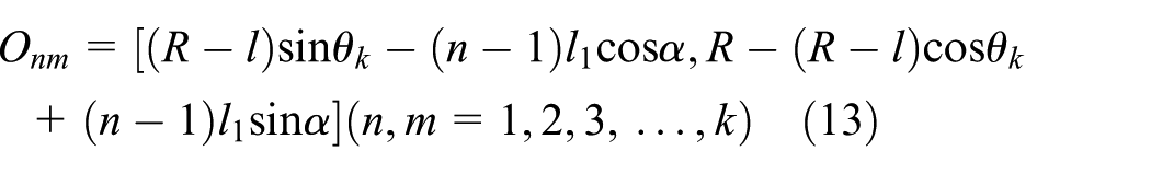
The angle between the connecting line of the center of two micro-pits of any two adjacent rows and the Y axis is α ∈ (0,π/2). The distribution position of the second row of micro-textures is


When α ∈ (π/2,π), formula (12) can be expressed as
The distribution boundary of micro-pits
Before the micro-texture is processed into the cemented carbide, the position where the micro-texture should be process is considered, that is, micro-textures should be processed in the contact area between the cutter and the chip. Because the theoretical calculation of the contact area is too complicated, the contact length and the contact width of the chip and the cutter considering different cutting depths and feed rates are measured by orthogonal test. The test of contact length and contact width between the cutter and the chip shows that the contact length lf and contact width lw are related to the cutting depth ap and the cutting width ae, respectively, which increase with the increase in cutting depth and cutting width, respectively. Using the method of MATLAB linear fitting to deal with the test data, the relationship between contact length lf and feed fz, and that between the contact width lap and cutting depth ap are obtained


The vertical distance between the first micro-texture in the first row and the cutter tip is H. As shown in Figure 6, the contact area between the cutter and the chip can be regarded as a rectangle. The relationship between the number of line m of the micro-pits and the contact length and that between the number of row n of the micro-pits and the contact width can be expressed as follows, respectively


Area occupancy of micro-pits.
By considering the two limiting positions of l, the range of it is

As known in formulas (7) and (19), the range of distance l1 is as follows

From formulas (14)–(19), when the cutting depth and cutting length are determined, the contact length and contact width of cutting tool can be determined by chip contact length and contact width, and the number of row of micro-textures and the number of micro-textures in each row can be determined. Experimental study shows that the cutting force increases with the increase in the distance between the first row and the tool edge. So, a reasonable choice of parameters of the micro-texture can be obtained by calculating the contact length, then the distance between the first row of micro-textures and the tool edge is quantitative, and finally, the cutting performance of ball-end milling cutter is optimized.
The area occupancy of the micro-texture
The area occupancy of the micro-pits refers to the ratio of the area of any micro-pit to the rhombus area, which includes four micro-pits. The research has found that the area occupancy q of the micro-pits has an impact on the tool wear of the surface, but most of the researches are lack of the influence laws. 19 Therefore, in this article, the influence of the area occupancy on the tool wear is explained by the combination of theories and experiments. As shown in Figure 6, when the angle between the connecting line of the center of two micro-pits of any two adjacent rows and the Y axis is α ∈ (0,π/2), it can be as follows


Formula (24) shows that in the contact area, when the distance l1 is a constant, the area occupancy increases with the increase in the radius of the micro-texture. When the radius is a constant, the area occupancy decreases with the increase in the distance of two adjacent micro-textures.
The mechanism of anti-friction of the micro-pits
In order to reduce the tool wear in machining the titanium alloy with the turning cutter, N He in Nanjing University of Aeronautics &Astronautics has been processed micro-textures on the rake face, the test of cutting titanium alloy with the micro-texture cutters and traditional ones. The experimental results show that the friction factor is low, so that the micro-texture can play a role of reducing friction. 20 Therefore, in the process of milling titanium alloy, theories and tests are used to study the effect of the micro-texture on reducing friction.
In metal processing, the chip is produced by shear slip when the metal flows through the shear surface. In the contact area between the chip and the cutter, the friction force on the rake face is related to the contact length,21,22 which can be expressed as

where

The range of kc is 0.75–0.83, τc is the yield stress at the bottom of metal layer, which is usually a constant. Forces of the three directions can be expressed as


When the cutter and the workpiece are in close contact, the coefficient of friction is


where φ denotes the shear angle; δ denotes friction angle; ω = φ + δ − γo, γo donates the rake angle; Ψr is residual deflection angle; Ψλ is chip flow angle; λs is cutting edge angle; τs is shear strength; Aσ is the contact area between the workpiece and the cutter; Fz is the axial force; the Fy is the radial force, and the Fx is the tangent force.
According to formula (25), because of the micro-pits, the contact length between the cutter and the chip is reduced, and the length of reduction is m times of the diameter, so the friction force on rake face decreases. Formula (27) shows that forces of the three directions decrease, so the resultant forces decrease. It is shown theoretically that the micro-texture has the effect of reducing the friction force and then reducing the resultant forces.
Optimization of parameters of micro-pits
Based on the Deform simulation software, the optimization simulation of parameters of the micro-pits is carried out. The cutter selected in this article is cemented carbide. The diameter of the cutter is 20 mm, the rake angle is 0°, the relief angle is 11°, the inclination angle of the plane is 15°, and the direction of cutting is upward along the inclined plane. The size of the workpiece is 5 mm × 2.5 mm × 1 mm. Johnson–Cook is an ideal rigid plastic strengthening model to describe the material of the workpiece, which will make the simulation results more close to the actual ones. The mathematical expression of J-C is

where
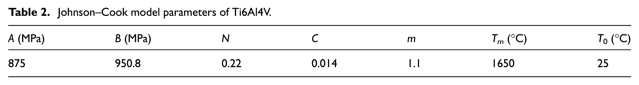
The material of the workpiece is Ti6Al4V titanium alloy, which is a typical sensitive material of temperature and strain, the melting point is 1560°C, and the density is about 4440 kg/m3. The constitutive parameters of the material are shown in Table 2.
Johnson–Cook model parameters of Ti6Al4V.
This article used adaptive re-meshing method of the Deform-3D software, which is one kind of the physical separation criterion. If the cutter embedded in the workpiece deeply, the mesh needs to be devised by this method in order to meet the contact conditions of the cutter and the workpiece. Its advantage is that the seriously distorted mesh can be made uniform, the precision of simulation calculation is guaranteed and the calculation is convergent. Figure 7 is a contrast diagram before and after the grid repartition.

Adaptive mesh repartition: (a) before re-meshing and (b) after re-meshing.
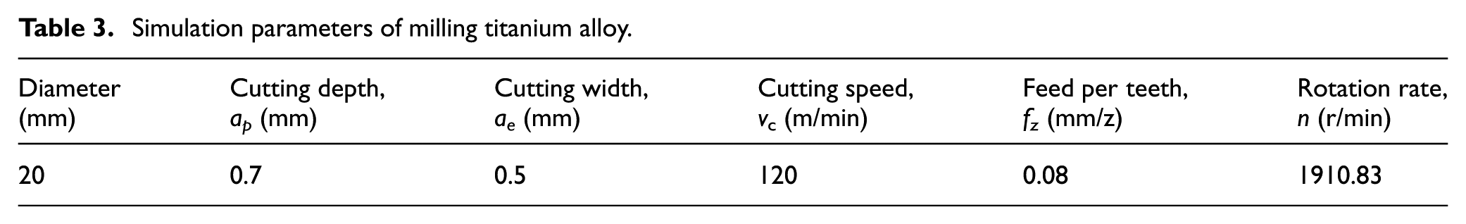
The micro-texture in the range of 30 to 70 μm is simulated to optimize the parameters of the micro-pits, and the cutting conditions of simulation are shown in Table 3.
Simulation parameters of milling titanium alloy.
Considering the influence of the minimum cutting thickness on the chip formation, the range of the distance l between the first row of micro-pits and the cutter edge is from 110 to 130 μm. The range of angle θ between the first row of micro-pits and the cutter center is from 0.1° to 0.5°, and the method of optimizing the structure parameters of the cutter is the range analysis. In order to simplify the calculation, according to the angle θ, H is calculated for the range analysis. The range of distance l1 between two adjacent micro-textures is from 110 to 140 μm. The simulation factor level is shown in Table 4.
Four-factor and five-level orthogonal test.

The orthogonal simulation test of milling forces of titanium alloy with the micro-texture ball-end milling cutter is carried out using Deform simulation software. The acquisition of a group of milling forces is shown in Figure 8. Milling forces after simulation are processed by the method of the range analysis. The results are shown in Table 5.
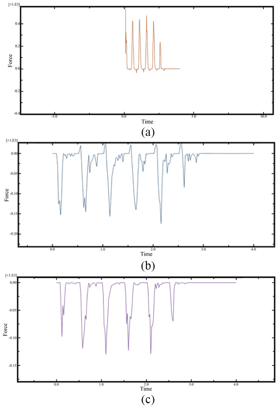
Three directions of forces for milling titanium alloy with micro-texture ball-end milling cutter: (a) milling force of the Fx direction, (b) milling force of the Fy direction, and (c) milling force of the Fz direction.
Range analysis.

From Table 5, it can be found that the order of the influence of the distribution parameters of the micro-texture on milling forces is the diameter D, the distance between two adjacent micro-pits l1, the distance between the first row of micro-pits and the cutter edge l, and the angle θ between the first row of micro-pits and the center of the cutter. In Figure 9, with the increase in the diameter, milling forces decrease first and then increase. With the increase in the distance l1, milling forces increase first and then decrease. With the increase in the distance l, milling forces continued to increase. With the increase in the angle θ, milling forces increase first and then decrease and finally increase. Regard forces as the evaluation target, the optimal parameters of the micro-texture is the diameter is 50 μm, the distance l is 110 μm, and the angle is 0.3°.

Relationship between parameters of the micro-texture and forces.
Test of the milling of titanium alloy with micro-texture ball-end milling cutter
Test of anti-friction performance of the micro-texture ball-end milling cutter
The comparison test of milling forces between the traditional cutters and the micro-texture ones is carried out, respectively. The parameters required for the test are shown in Table 3. The site of the test is shown in Figure 10. The size of the workpiece is 210 mm × 70 mm × 35 mm, and the dynamometer is Kistler 9257. The diameter of the micro-texture is 50 μm and the depth is 305 μm, and the distance between the first row of micro-pits and the cutter edge is 110 μm. In the experiment, forces are measured in the three positions on the inclined plane, respectively. Forces contain three direction forces, and three root mean square values are calculated. From the average of the three values, forces are shown in Figures 11 and 13, respectively. So, forces are called average root mean square values. The test results are shown in Figure 13.

Test site.

Comparison of test results.
Scanning electron microscope is used to observe the structure of micro-textures on the rake face, which is shown in Figure 12. The tool wear on the rake face of the traditional cutter is serious. It is known that the micro-pits have the function of accommodating impurities such as the chip and abrasive particles.

Surface morphology of micro-textured ball-end milling cutter after laser processing.
The change laws of milling forces are analyzed. In the stage A, there are melting residues on the surface after processing micro-textures, the roughness of the rake face increases, micro-textures will not play a role in reducing friction, so in the early processing, milling forces produced by the traditional cutter is smaller than that produced by the micro-texture ball-end milling cutter. With the increase in cutting stroke, the melting residues gradually shed and micro-textures play a role of anti-friction. The maximum difference is about 80 N, which accounts for 20% of the milling forces produced by the traditional cutter. From the stage B to C, milling forces produced by the micro-texture ball-end milling cutter are smaller than that of the traditional cutter. Therefore, micro-textures are processed into the ball-end milling cutter, which can effectively reduce the friction during the milling process of titanium alloy.
Test of the influence of the diameter of micro-pits on milling forces
The micro-texture ball-end milling cutters with different diameters were used to the test, and the influence laws of changing diameters on the cutting performance were analyzed. The cutting parameters, as shown in Table 2, it can be seen that with the increase in the diameter of micro-pits, the resultant of forces decreases first and then increases, indicating that there is a reasonable value of the diameter of the micro-pits, so that performance of the anti-friction and anti-wear of the cutter is the best. As shown in Figure 13, when the diameter of the micro-pit is 50 μm, the resultant of forces is the smallest, which is in accordance with the simulation optimization results.

Resultant of forces of milling titanium alloy with different diameters of micro-pits ball-end milling cutter.
When the diameter is small, there is a little chip in micro-pits, which mostly bonds on the rake face. The roughness of the rake face increases and then results in increasing of cutting forces. When the diameter is too large, there are more chips in the micro-pits under the action of forces. There is a second cutting when the chip flows the edge of a micro-pit and then resultant of forces increase accordingly. It is indicated that although the increase in the diameter can reduce the contact length between the chip and the cutter, the phenomenon of the second cutting is serious. So, the diameter is not good if it is too large. But the phenomenon of the second cutting is serious. Compared with the traditional cutter, when the diameter of the micro-texture is 50 μm, the resultant of forces produced by the micro-texture ball-end milling cutter is smaller than that by the traditional one, which indicates that cutting performance of the micro-texture ball-end milling cutter is better than that of traditional one.
Test of the influence of the area occupancy of micro-pits on the tool wear
The effect of the area occupancy of the micro-pits on the tool wear is analyzed by the milling test, and the parameters of the test are shown in Table 3. The VDL-1000E three-axis computer numerical control (CNC) milling machine is used as the equipment. After the test, the degree of tool wear is observed with the ultra-depth of field, as shown in Table 6.
Surface morphology of the tool wear.
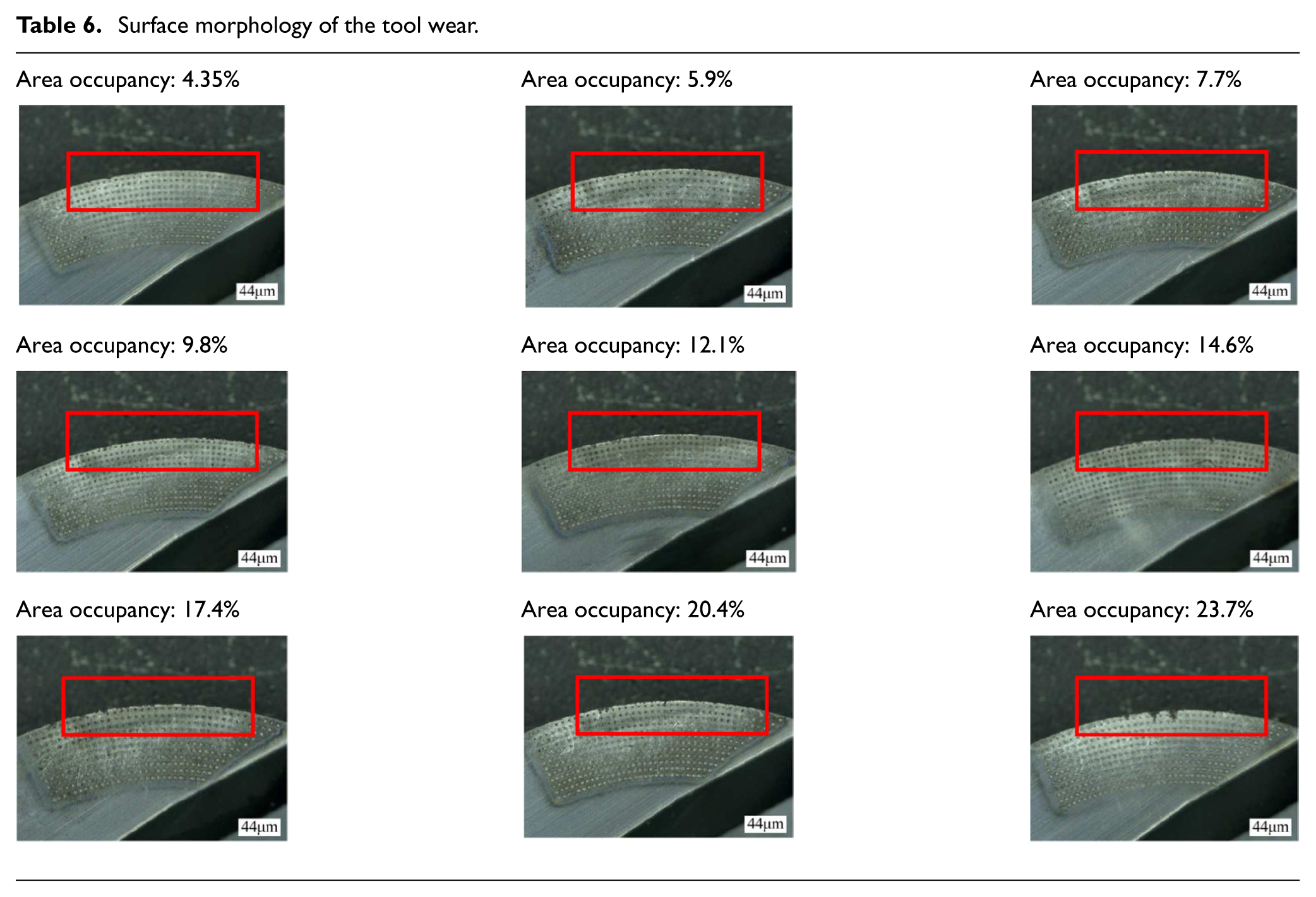
It can be seen from Table 6, when the distance between two adjacent micro-textures is a constant, with the increase in the area occupancy, the tool wear increases. Although micro-texture has the effect of anti-wear and anti-friction, the increase in diameter will lead to increase in the friction coefficient of the rake face, and the degree of the increase in the friction is greater than that of anti-friction of the micro-texture. Therefore, the degree of tool wear will increase. When the diameter of micro-pits reaches a certain extent, the edge of micro-pits will play the role of the second cutting, which results in the fine chip remaining in the micro-pits and then the degree of the tool wear further increases. Therefore, considering the other factors, the diameter of micro-pits has a reasonable value, which makes the performance of anti-wear and anti-friction best.
Conclusion
Based on the geometry of micro-texture the ball-end milling cutter, the model of geometric parameters of a micro-pit was established, and the model was further modified by the test. On the basis of the established model, the tests were carried out by changing the diameter of parameters of the micro-texture, and the influence laws of changing diameter on cutting forces were obtained and analyzed. The test found that with the increase in the diameter, the milling force decreased first and then increased, which indicated that the diameter of micro-pits had a reasonable value to make the performance of anti-friction best. The above conclusions provide a theoretical basis for further study of the influence of parameters of the micro-texture on the cutting performance of the cutter.
Based on the determination of the contact area between the cutter and the chip, the theoretical distribution laws in this region were obtained. The boundary conditions of the distribution were defined. The theoretical model of the area occupancy was established. The parameters of micro-textures were optimized by the simulation, the simulation results showed that when the diameter was 50 μm, the distance l between the first row of micro-pits and the tool edge was 110 μm, the angle between the first row of different locations of the micro-texture and the center of cutter was 0.3°, and the milling force was minimum. The influence of the tool wear on the area occupancy was studied by the test. The results showed that when the distance between two adjacent rows of the micro-pits was a constant, with the increase in the area occupancy, the tool wear increased. The above conclusions provided a reference for the rational selection of parameters and the accurate preparation of micro-textures.
Based on the effect of anti-friction of the micro-texture, the anti-friction mechanism of the micro-texture ball-end milling cutter was revealed in theory, the excellent property of anti-friction of micro-texture were further confirmed. All the above provide a theoretical basis for the efficient processing of titanium alloy, and the optimization design of the cutter has played a supporting role.
Footnotes
Handling Editor: Kang Cheung Chan
Declaration of conflicting interests
The author(s) declared no potential conflicts of interest with respect to the research, authorship, and/or publication of this article.
Funding
The author(s) disclosed receipt of the following financial support for the research, authorship, and/or publication of this article: This work was financially supported by the National Nature Science Foundation of China (No. 51375126).