
Abstract
In this article, a new design scheme of x-by-wire steering suspension system is proposed, which aims to solve the adaptation problem of the traditional steering system, suspension system, and the electric wheel. It meets the requirement of four-wheel independent steering function with large scale. The design keeps wheel steering center axis to coincide with the virtual wheel kingpin, thereby realizing the application of the center point steering independent suspension system in electric wheels. In addition, modular design is adopted to reduce the coupling between the system and the car body, thereby realizing the generalization of the front and rear steering suspension system, and it also decreases the number of components. Furthermore, the theoretical analysis and parameter design of the self-aligning torque of the suspension are carried out. The multi-body dynamics model of system is established, and the performance is simulated in both time domain and frequency domain. The comparison test shows that the center point steering independent suspension has higher feasibility. Finally, a prototype of the system is developed, which provides a new idea for the designing of chassis for electric vehicles.
Keywords
Introduction
With the rapid development of electric powered vehicles (EV), its wide adoption is becoming an inevitable trend. Currently, a research hotspot in the field is the four-wheel-independent EV base on x-by-wire technology, of which all four wheels can be driven, brake, and steered independently. 1 By the independent control of the three subsystems, it is easy for the x-by-wire (XBW) technology to unify the current decentralized structure of active safety systems and realizes the integration of the chassis system 2 (such as direct yaw control [DYC], traction control system [TCS], Electronic Stability Program [ESP], electronic brakeforce distribution [EBD]) for stability. With simpler chassis structure and shorter transmission chain, this type of technology can greatly improve vehicle stability, safety, comfort, and economy.
To realize the super maneuvers such as crab, lateral movement, and zero radius turning, four wheels of vehicle should have the ability to steer independently four wheel independent steering system (4WIS) with a large degree of freedom. Obviously, it is difficult for traditional steering suspension system to achieve the above functions with trapezoidal steering mechanism. In addition, the radial and axial dimensions of the wheel motor block the installation space that originally belonged to the steering system and suspension system. In fact, the narrow rim space has restricted the layout of the traditional suspension and steering mechanism, and the installation of the hub motor makes this part of the space further reduced. This leads to conflict between the steering system and the suspension system in the layout parameters, which leading to the larger kingpin offset (as shown in Figure 1(a)), and thus seriously deteriorates vehicle handling stability and ride comfort, even leading to kinematic interference of the chassis structure. 3

Schematic diagram of CPSIS.
Special research related to steering suspension system for electric wheel vehicle, typically Michelin active wheel, 4 adopts hydraulic active suspension with the steering, suspension, and braking systems integrated into the rim, and the kingpin is arranged in the center of the wheel to realize center point steering. However, it has specific requirements for the device size, package, heat dissipation, and antifouling. Similarly, Siemens VDO, an automotive electronics supplier, has proposed a brake-by-wire technology (BBW) solution for brake by wire. In contrast, the Australia Eze Corp company launched the Smart Wheel chassis concept. 5 However, the bearing capacity is weak. Volvo has put forward the idea of Autonomous Corner Module wheel, 6 realizing wheel integration with double steering actuator, active suspension, and shock absorber. Unfortunately, the system is over encumbering.
Zhuo et al. 7 investigated a kingpin offset double wishbone suspension guiding mechanism and a bevel gear steering mechanism, to realize arbitrary rotation and translation, but the structures are quite complex. Besides, Dr Shi 8 has designed a new double wishbone front suspension system, which solves the kingpin offset problem caused by the installation of the in-wheel motor through the virtual joints to control the kingpin parameters. In addition, some scholars3,9–11 have been proposed improvement plans and measures to diminish large unspring mass negative effects caused by the electric wheel. A comparative study 12 of these methods used to reduce negative factors is given in detail in a study.
Presently, the research on the steering suspension system for EV mostly focuses on traditional structures, which is used to alleviate the negative influence of the unspring quality. In contrast, the design and research of steering suspension systems for electric wheel are rare. Therefore, in this study, a new design scheme of center point steering independent suspension (CPSIS) system is proposed to solve the adaptation problem between traditional steering system, suspension system, and electric wheel, and to realize application of CPSIS system on the electric wheel. The scheme realizes the 4WIS function with simple mechanism. With modular designs, the number of parts and components is greatly reduced. The design, analysis, and simulation of the CPSIS system are presented in the following sections.
CPSIS system
The “center point steering” suspension system refers to the suspension system where the kingpin vertically passes through the tire center, which is used to solve the large kingpin offset problem (as shown Figure 1(a)) caused by trapezium, arrangement of braking system, and other reasons. 13 As known, large kingpin offset would result in excessive kingpin roll moment. The CPSIS system is divided into the ground center type and the ideal center type, as shown in Figure 1(b).
In the ideal center type, because there is no kingpin offset, vertical action of the ground on the wheels does not produce roll moments around the kingpin, the steering operation is light, and road sense feedback is good. However, due to chassis structure and rim space, it is difficult for this steering suspension system to obtain ideal positioning parameters; hence, it is seldom used. Furthermore, due to the axial size of the hub motor, it is difficult to coordinate with its power, resulting in excessive overhead of center steering realized through the type structure.
The XBW CPSIS is designed to ensure real-time coincidence between the kingpin and the wheel steering shaft through the virtual kingpin. In this way, the application of CPSIS in the electric wheel vehicle is resolved. The modular design reduces the coupling relation between the steering system, suspension system, and the electric wheel system within the design parameters, so the module structure is relatively independent. As shown in Figure 2, the three overall modules are the electric wheel system (A), suspension system (B), and steering system (C).

Structure of CPSIS system.
In particular, the motor shaft (A6) of the electric wheel system (A) passes through the hole of the connecting plate (B1), which is fixed by a flat key, a double thrust nut (A7), and a thrust washer. The suspension arm (B6) is connected to the convex shaft (C1) of the steering system (C) via a bolt set. Finally, the clamping band of the cantilever clamping device (D) is fixed to the sleeve (C2) of the steering system (C), thereby completing the indirect connection between the three assemblies and the body. When turning, the deflecting torque is generated by the stepping motor (C9) and is outputted through the convex shaft (C1). The electric wheel system (A) and the suspension system (B) are integrally deflected under the effort of the torque, completing the steering operation.
The structural feature of the system is the steering pin that passes through the neutral surface of the tire, which is just above the wheel. The design ensures that the output shaft and the virtual kingpin coincide at any steering moment, so the wheel alignment parameters remain unchanged during wheel jump. In terms of overall structure, the electric wheel system is connected with the suspension and other parts through the shaft, and the steering system is arranged above the tire, thereby solving the problem of adaptation and interference caused by insufficient transverse space in the rim. The vehicle contains four identical CPSIS and electric wheel modules, which simplifies the number and type of parts by the universal design; it is also low cost for mass production. The physical object of the system is shown in Figure 3.
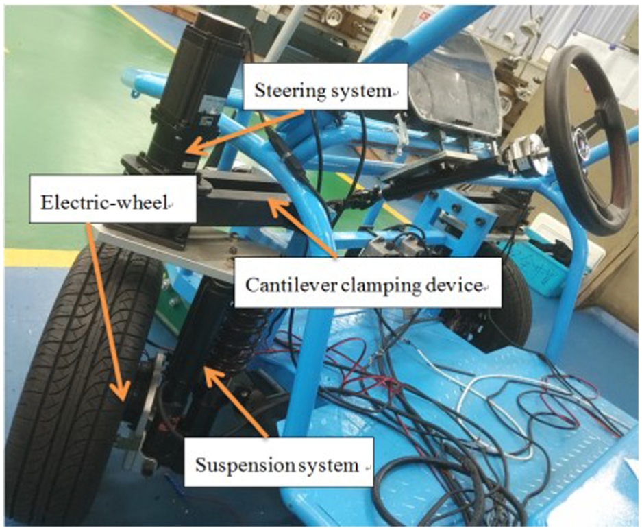
Prototype of XBW CPSIS system.
Mechanical analysis
Topology is a fundamental determinant of suspension performance. 14 Compared with conventional system, the new design has no mechanical connection between the wheel and the body. As a result, the system restraint on wheel movement is removed. Therefore, it is necessary to analyze the kinematics and mechanical properties of the steering suspension system.
The projection of the intersection point of the axis of the wheel with the longitudinal symmetry plane of the vehicle on the ground, denoted as O, is the origin. The ISO coordination system establishes the system coordinates of the suspension OXYZ; the forward direction of the automobile is defined as the positive direction in the x-axis. Meanwhile, the right-hand rule is used to establish the tire coordinate system O3xyz. From a kinematics point of view, a suspension system can be defined as a combination of links and joints. The mechanism, topology, and force of CPSIS system are shown in Figure 4.

Topology and force diagram of XBW CPSIS system.
Among which, O1 and O2 represent the upper and lower clamping points of the clamping cantilever and the body, respectively. O3 is the center of contact between the tire and the ground. The C and D points are the intersection points of the wheel center and the kingpin extension line, respectively. E, F, G, and H are the hinge points between the damping, shock absorbers, connecting plates, and the suspension arms, respectively. σ, δ are the deflection angle of the tire and the steering angle of the wheel. ξ1, ξ2 are mechanical drag distance and air drag distance. ξy is the tire lateral deformation.
Dynamics parameter calculation
The initial coordinate vectors of the points above are as follows

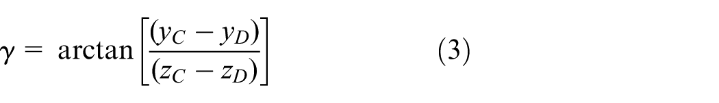
The most important kinematic parameters in a suspension that affects handling, road holding, and ride characteristics of a vehicle are the camber angle (γ), caster angle (τ), kingpin inclination (σ), and toe angle (ε). 15 As shown in Figure 4, they are calculated as follows


Dynamics parameter analysis
The key to the suspension design is to achieve ideal control of the six-component force of the tire by a reasonable design of the suspension layout parameters. Because the road sense feedback can be designed ideally through the steering-by-wire technology (SBW) part, the consideration of wheel positioning is simply due to the influence on the vehicle’s steady running performance. In addition, due of the lack of wheel movement constraint, the design of the vehicle’s straight ride stability should be focused on. In other words, the self-aligning torque of the z-axis should be properly controlled. Moreover, the self-aligning torque is critical to the selection of the steering motor, which consists of two parts: the frictional resistance moment of the steering system and the back torque of the tire. 16
The sum self-aligning torque is as follows:

where Js represents the moment of inertia on the kingpin, Bs is the damping coefficient when the wheel moves around the kingpin, Mc is the friction torque cause by the wheel movement around the kingpin, an approximate constant, MT is the self-aligning torque determined by suspension dynamic parameter, and it can be expressed as

Among them, Mσ, Mτ, Mγ, and Mε represent the self-aligning torque determined by the kingpin inclination angle (σ), kingpin caster angle (τ), tire camber angle (γ), and toe angle (ε), respectively. The main function of the τ is to form the self-aligning torque during the steering operation. τ is able to influence the mechanical drag (ξ1) and pneumatic tire drag (ξ2), thereby changing the acting arm on the tire lateral force, automatically forming a self-aligning torque. Mγ can be described as


The effect arm e is a projection in the tire longitudinal symmetry plate, and e consists of the ξ1 and the ξ2.Fy stands for the lateral force of the tire; Fyt stands for the projection of tire force on the lateral side cause by other positioning parameters; m is the car quality; ay is the lateral acceleration of the vehicle; uc is the longitudinal speed; λ is the curve curvature of the road.
While δ = 0, e is at the maximum (Mτ is also at its maximum), and the vehicle is going straight; when δ = π/2, e and Mτ are at the minimum value, and the vehicle is in 90° turning operation. Under the circumstance of conventional small amplitude steering, the values of Mτ will never be zero to ensure the aligning torque. In addition, the drag is associated with wheel load conditions, so the mechanical drag should have a certain margin. In traditional suspension, the kingpin drag is usually 0–30 mm. 17 In view of higher kingpin’s position in this design, τ should be a smaller value, which is set to 1.5°. The τ can be adjusted by adjusting the arm connection point on the body.
Due to σ, the steering wheel, together with the car, has a displacement on the Z-axis (as shown in Figure 5(a)). At this point, the system produces energy transfer, and the change in potential energy will be released in the form of a self-aligning torque as the steering force disappears, resulting in the wheels returning to the middle position.

The influence of σ and γ on the self-aligning torque.
If the wheel steering angle is at 180°, the displacement of the vehicle raised can be expressed as hσ = ψ sin(2·σ), where ψ is the inset of kingpin. Accordingly, while the angle is δ, the self-aligning torque is

Obviously, decrease in σ will lead to the reduction of kingpin offset, thereby weakening the aligning torque. In consideration of the virtual kingpin passing through the tire neutral plane, regardless of tire deformation, the theoretic values of kingpin offset are zero, so the self-aligning torque caused by σ is negligible.
The γ of the tire is mainly produced in response to the phenomenon of partial wear on the tire. Because the axle will deform downward after loading, the γ can effectively offset the deformation and reduce the wear on the inner shoulder of the tire. γ is generally around 1 18

Fγy is the component of the Fz in the y direction due to the deflection of the γ (as shown in Figure 5(b)). As γ is very small, equation (11) can be wrote as Fγy = Fz·γ. Since the direction of Fγ always points to the inside of the vehicle, it always reverses the direction of Fy, thereby increasing the effect of self-aligning torque. At the same time, the γ has an influence on the ξy and will affect the self-aligning torque under the influence of the Fx. Therefore, the self-aligning torque produced by the γ is indirectly composed of two parts, Fγy and Fx

It is easy for the Fγy to cause uneven loading on the tapered bearing at the lower end of the kingpin and increase the dry friction torque of steering. Moreover, the unbalanced axial force increases the additional load on the two ends of the bearing and fastening nut on the hub motor, which have a negative impact on the running smoothness of the motor. Considering the lighter load of the platform and reduced load of the motor, the γ is set to 0.5°.
The ε is generated by the tire camber, mainly to eliminate the coning motion caused by the γ. As a result of the ε, the force Fx of the tire has a component Fεy in the y direction (as shown in Figure 6), and this component affects the self-aligning torque by the effective arm length e. The Mε can be expressed as


The influence of ε on the self-aligning torque.
The lateral component Fεy will cause compression on the bearings of the motor and cause additional load on the fastening device; hence, the toe angle should not be too large.
Establishment of simulation model
Simplified mathematical models with less degrees of freedom cannot take into account the uneven effects of roll, pitch, axial load transfer and side bias, and the accuracy of the model is low. Therefore, based on the ADAMS/view, an accurate multi-body virtual prototype of CPSIS and electric wheel is established. Meanwhile, the detailed contrast model of the double wishbone steering suspension system with the same parameters is built on the CarSim platform. Finally, the comparative study of the two systems is performed with Simulink.
Modeling of 4WIS algorithm
The monorail vehicle model with 2 degrees of freedom is commonly used in vehicle handling stability controller design. Here, assuming that the left and right wheel angles are equal on the same shaft, the 4WIS control algorithm is designed, and the model analysis is shown in Figure 7

where lf(l r ) is the distance from the center of gravity to the front (rear) axis, Cαf(C αr ) is the cornering stiffness for the front (rear) wheel, Izz is the rotary inertia of yaw, ω is the yaw rate of the vehicle, uc(v) is the longitudinal (lateral) speed of the vehicle, and δf(δr) is the front (real) steering angle.

Bicycle model for four-wheel-steering vehicle.
In the four-wheel-steering (4WS) control algorithm, the δr can be considered as two parts: one is the direct in proportion to the δf and the other is related to the uc and ω. The δr can be defined as follows 19

where η1 and η2 are the parameters. And η2 will change the system eigenvalues, thus changes the vehicle steering characteristics. 20 In order to reduce the influence on the inherent characteristics of suspension caused by η2, and thus the parameters η2 should be zero. In addition, to make the vehicle has good handling stability in most of the time, the control target is set as v = 0. Simplifying equations (14) and (15), there is

Modeling of XBW CPSIS system
The test vehicle used in this research is a self-developed platform for electric wheel vehicle test. The test and measurement of the electric wheel vehicle test platform are carried out. The relevant parameters are shown in Table 1.
Main parameters of the XBW electric vehicle.

XBW: x-by-wire.
Detailed three-dimensional modeling of the vehicle including CPSIS and electric wheel system is carried out through CATIA (as shown in Figure 8(a)). The digital model was imported into ADAMS software for cleanup and constraints, springs, damping, friction, and contact were added, and inputs were made based on actual part size parameters and mechanical parameters (such as mass, centroid, moment of inertia, and stiffness). In this process, the accuracy of the hard point position of the suspension must be fully guaranteed. After programming the tire and road properties, the final virtual prototype model is set up, as shown in Figure 8(b).

(a) CAD model and (b) virtual prototype of vehicle with XBW CPSIS system.
Modeling of contrast system
Here, a contrast system based on traditional steering suspension is established through CarSim. In this model, the topological relationship of different components and the influence of nonlinear components such as bushing, shock absorber, and limit block is considered in detail. Therefore, the establishment of the standard vehicle has high accuracy and is in good agreement with the real vehicle. The contrast system is suitable for the simulation and comparative analysis of nonlinear virtual prototypes.
According to the arrangement of the CPSIS, the parameter, such as spring stiffness, damping parameters of contrast model, established by CarSim, is consistent with equivalent quantity 21 of designed system. The rest of the parameters of the contrast vehicle model and tire properties are also consistent with the virtual prototype, as shown in Table 1. In order to make comparative analysis variables unique, the CarSim 4WS control file should be edited to realize the joint simulation with the Simulink.
Simulation and analysis
Presently, the steering tests on suspension system are step response test, double lane change test, continuous serpentine test, and so on. According to GB/T6323-2014 standard, the time domain response analysis, frequency response analysis, and performance evaluation of the CPSIS system are carried out by the joint simulation with Simulink.
Step steer input test
Due to the open-loop simulation, the step steer input test emphasizes the inherent properties of the system. Taking 60 km/h as the boundary, and taking 5 km/h as the speed tolerance, the contrast tests were made in 0.1 s to give the front wheels 2°, 4°, 6°, and 8°, respectively. The following are several representative simulation conditions: the curves (Figure 9(a)) of the yaw rate with respect to longitudinal velocity (step angle of 8°); the curves (Figure 9(b)) of the yaw rate with respect to front steering angle (speed at 60 km/h). (ADAMS and CarSim represent the XBW CPSIS system built by ADAMS software and the contrast steering suspension system built by CarSim software, respectively; this remains the same below).

Yaw rate comparison-step steer input at different conditions: (a) variable speed with step angle of 8° and (b) variable step angle with speed at 60 km/h.
As shown in Figure 9(a), when the step angle is fixed, both yaw rate responses are in the same trend. As the speed increases, both yaw rates increase first and then decrease, finally all within a certain reasonable range. However, there are differences in the steady-state values and the transition process. The difference in steady state values is greater at high speeds and smaller at low speeds, and the dynamic changes in the contrast system are more detailed.
When the speed is constant (Figure 9(b)), both yaw rate responses increase gradually when step angle becomes larger, and their steady-state difference also increases. As a whole, due to double damping, the yaw rate response of the CPSIS system is better than the contrast system in transition time, overshoot, or stability. The analysis of the appeal shows that the designed system can meet the stability requirements under the step angle input and has some advantages in response speed and flexibility.
Of course, any steering suspension system must meet the characteristics of understeer, which is critical to vehicle handling stability. The steady-state response is commonly expressed by the yaw rate gain.
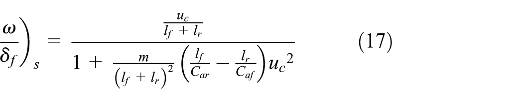
Since the actual vehicle has strong nonlinearity, the above formula is only applicable to qualitative judgment and applicable to the condition within 0.4 g of lateral acceleration. In order to improve accuracy, steady-state response values under different conditions were calculated, as shown in Table 2.
Steady-state value of yaw rate at step angles input under different conditions.
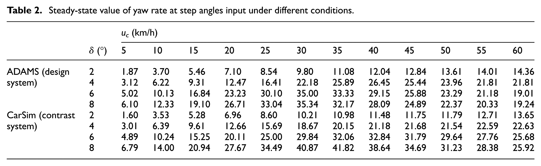
The steady-state gain of the yaw rate is plotted as shown in Figure 10.

Yaw rate gain comparison: (a) the center point steering suspension system and (b) the contrast steering suspension system.
As a whole, the steady-state yaw rate gain and tendency of the two are similar. Under low-speed and small steering angle conditions, curve accorded with normal proportion, mainly because the system is still in the linear range; thus, it better meets equation (17). As speed and step angle increase, the curve does not follow in proportion; the system shows strong nonlinearity, and with the increase of speed, the value curve increases initially and then decreases, so the two systems both have certain understeer characteristics. In the above conditions, the critical speed ucr of CPSIS system is about 35 m/s, while the contrast system critical speed u`cr around 40 m/s, so the contrast system has stronger understeer characteristics.
Continuous steering test
S-shaped test belongs to a continuous steering test, which reflects the vehicle’s tracking quality and the continuous dynamic response characteristics of the suspension. At 60 km/h, S-shaped test simulation was preformed, and the front wheel angle amplitude is 1° with a period of 4 s. Simulation result comparisons are shown in Figure 11.

Comparison of S-shaped simulation test: (a) yaw rate response, (b) lateral acceleration response, (c) roll angle response, and (d) trajectory of vehicle centroid.
In the S-shaped test simulation, the response of parameters of CPSIS is highly consistent with the contrast system; they are stable within a reasonable range. The curves indicate that the CPSIS system is able to meet the stability requirements under the conditions of the continuous steering input. In the above curve, the smoothness of the yaw rate curve and the lateral acceleration of the CPSIS system is slightly inferior when approaching zero. Therefore, the change rate of yaw rate acceleration and lateral velocity acceleration is larger than the conventional suspension when near the zero value. This phenomenon may be caused by a lack of self-aligning torque in the center steering suspension system.
Pulse test
The kinematic frequency characteristic of the suspension is an important index to evaluate the dynamic response characteristics of vehicle handling stability. The natural property of the steering suspension system is indirectly obtained by observing the response of the system to the input sinusoidal waves of different frequencies. 22 Based on the theorem of the linear superposition and the Fourier transformation, it can be seen that any random signal can be decomposed into several linear superposition of sine waves. Thus, the frequency response is analyzed by pulse wave.
According to the standard GB/T 6323.3-1994, when the vehicle is driving in a straight line under a certain speed condition, a certain steering angle is given to the steering wheel, so that the maximum lateral acceleration of the vehicle in the transition process is 4 m s−2. In order to obtain a wider frequency range, the pulse width is controlled to 0.4 s, and the simulation results are shown in Figure 12.
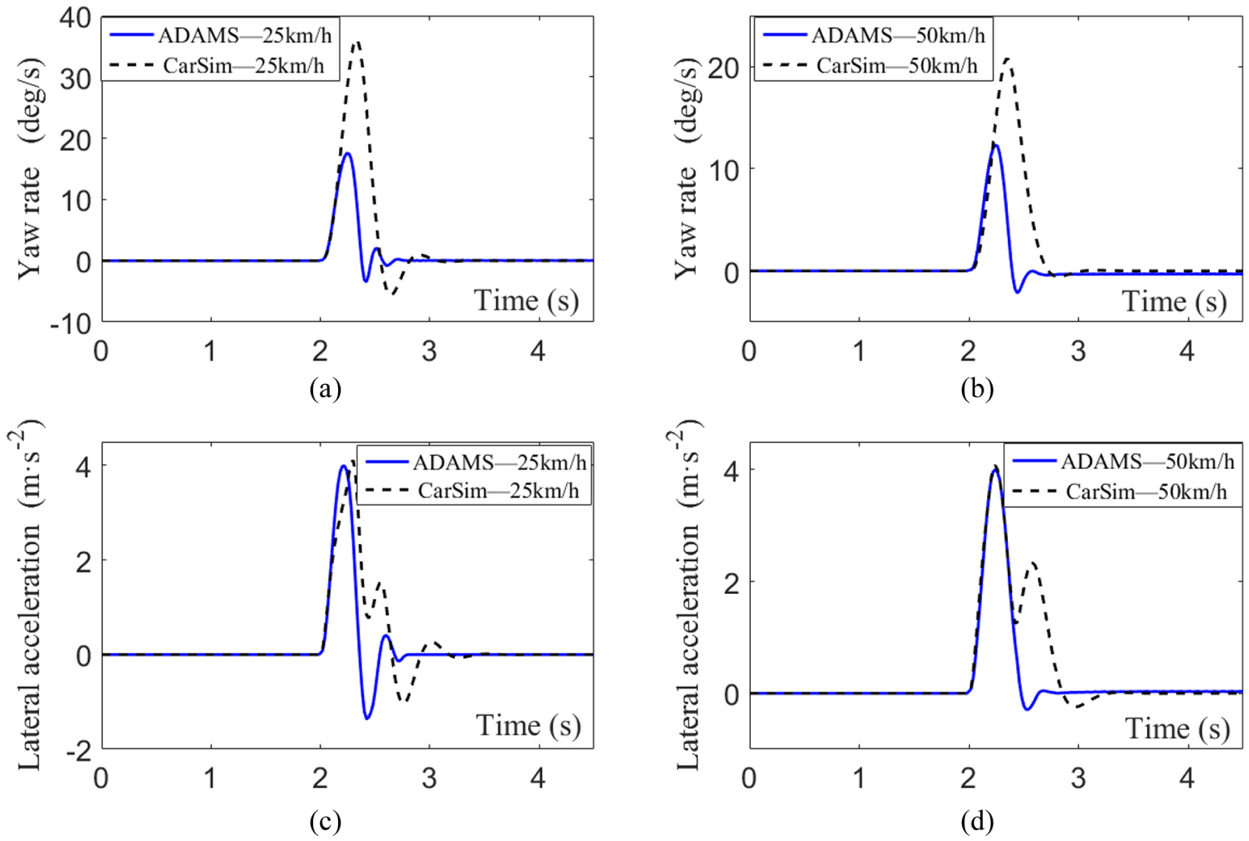
Comparison-plus input test at different velocities: (a) yaw rate response (25 km/h), (b) yaw rate response (50 km/h), (c) lateral acceleration response (25 km/h), and (d) lateral acceleration response (50 km/h).
The fast Fourier transformation (FFT) of the input and output is preformed, and the frequency response characteristics of the system can be obtained via equations (18) and (19)
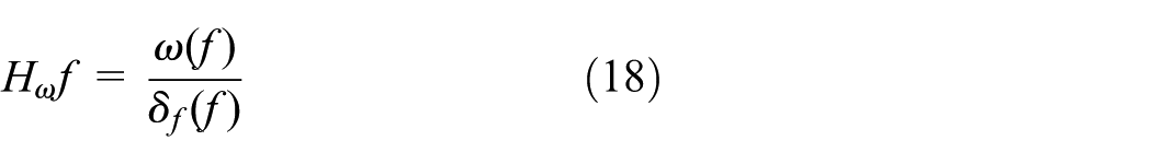
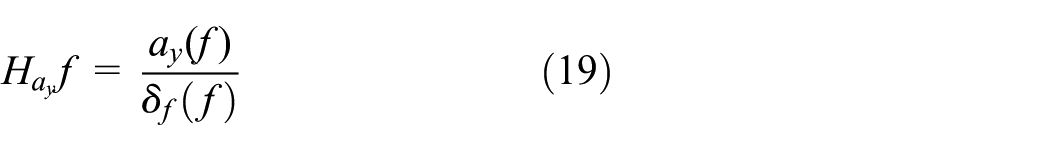
where Hω(f) and Hay(f) are yaw velocity and lateral acceleration gain of FFT, respectively; ω(f) and ay(f) are the output signal of the yaw rate and lateral acceleration of FFT; f is the frequency; δf(f) is the front wheel input angle of FFT.
The driver control operation frequency is roughly 0.5–1.5 Hz. 23 Therefore, more attention is paid to the low-frequency input characteristics of steering suspension system. After the fast Fourier transform, the 1–4 Hz frequency band of the signal is analyzed by frequency response, as shown in Figures 13 and 14.
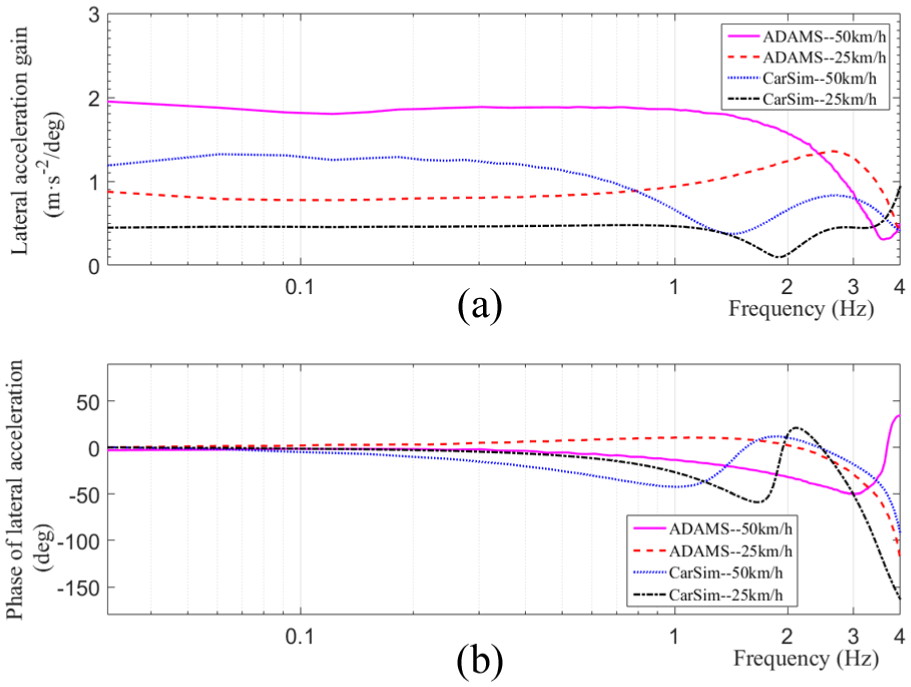
Frequency comparison of yaw rate at different velocities: (a) frequency analysis of lateral acceleration gain and (b) frequency analysis of phase of lateral acceleration.

Frequency comparison of lateral acceleration at different velocities: (a) frequency analysis of yaw rate gain and (b) frequency analysis of phase of yaw rate.
As illustrated in Figure 13(a), at low frequencies, the frequency response characteristics of the designed system and the contrast system vary little, but the difference begins to show at high frequencies. The CPSIS system has larger yaw rate gain than the contrast system, so it outputs relatively sensitive response compared to the smaller steering operation. In contrast, the yaw rate gain of the contrast system begins to decrease after 1.5 Hz, but the value of the designed system can be kept constant over a wider frequency range, which indicates that the designed system can maintain operation quality in a wider frequency range. It shows that the linearity of the designed system is wide enough to reduce the additional driving load caused by the driver’s compensation behavior when steering.
Figure 13(b) shows that the yaw rate phase angles of the two systems are consistent at low frequencies and they are insensitive to frequency and velocity variations. The difference between the two is that the phase lag angle of the contrast system is obviously larger than CPSIS system, the reason lies in the designed system using the steering motor to complete steering instead of steering trapezium, and thus steering transmission chain is shorter, so the response delay is less. In this respect, the designed system has some advantages.
In the lateral acceleration frequency response (Figure 14(a)), when input with low frequency and low velocity, the difference in lateral acceleration frequency response of the two systems is smaller, and with the increase of vehicle speed and frequency, the difference becomes larger. Overall, because the lateral acceleration of the contrast system is insensitive to frequency, it is indirectly proved that the lateral force control of the contrast system is slightly better than the designed system. The above conclusion is consistent with the conclusion of S-shaped test simulation.
In low-frequency stages, the acceleration phase lag angles (Figure 14(b)) of the two systems are both insensitive to velocity. With the increase of frequency, the frequency response phase angle of the contrast system experienced a change from hysteresis to advance. In 50 and 25 km/h, the phase inversion frequency is roughly 1.5 and 1.9 Hz, and the frequency of phase inversion decreases when the speed increases. However, the trend of phase lag angle of the CPSIS system is obviously slower. These phenomena are also mainly caused by locking of mechanical constraint of the design system on the wheel movement, and thus, the lateral force control of CPSIS system requires extra attention.
Conclusion
The shortage of space caused by the installation of in-wheel motors poses a challenge to the traditional suspension layout. This paper designs and develops a new CPSIS system. This design solves the adaptation problem of electric wheel and traditional steering suspension system in EV. Meanwhile, the modular design is adopted to reduce the number of parts, simplifying the vehicle structure, provides the layout of flexible suspension, as well as reducing design difficulty.
The simulation results show that compared with traditional wishbone suspension, there are certain advantages including speed and maneuverability in the CPSIS system, although the lateral dynamic needs to be improved and focused on. The remaining performances of the two systems are similar. The designed CPSIS system can meet the requirements for stability, handling, and safety in many working conditions. The scheme can be used as a useful reference for the design and development of hub electric vehicle chassis system.
Footnotes
Handling Editor: Shun-Peng Zhu
Declaration of conflicting interests
The author(s) declared no potential conflicts of interest with respect to the research, authorship, and/or publication of this article.
Funding
The author(s) disclosed receipt of the following financial support for the research, authorship, and/or publication of this article: This work was supported by the National Natural Science Foundation of China (nos 61403259, 51577120) and Science and Technology Research and Development Foundation of Shenzhen (no. JCYJ20170302142107025). The authors would like to sincerely acknowledge all the support.