
Abstract
In order to improve the working performance and service life of the in-wheel motor for micro-electric vehicle, the outer rotor in-wheel motor of micro-electric vehicle is designed and the model is analyzed, which are based on the theory of electromagnetic field and working principle of the motor. Besides, the size of the micro-electric vehicle wheel is optimized and designed, and the length of the internal and external diameters of inner stator and outer rotor of the outer rotor in-wheel motor are designed and calculated. According to the air-gap selection principles, the parameter of air gap is designed and determined. Some important parameters are derived and calculated, such as the pole-arc coefficient, air-gap magnetic flux density, gap coefficient, and the coefficient of air-gap flux waveforms. The finite element model outer rotor of in-wheel motor is established by Ansoft Maxwell software, and the finite element mesh subdivision is carried on. Magnetic flux densities, magnetic field strength, and magnetic line of force are analyzed by dynamic simulation, and the starting characteristics and the change of torque curve are studied and analyzed. The final simulation analysis results are in good agreement with the design calculation results, which indicate that design scheme of outer rotor in-wheel motor is useful that can meet the performance requirements of outer rotor in-wheel motor for micro-electric vehicle.
Introduction
Vehicle is regarded as the most common means of traffic and transportation, which is playing an increasingly important role in people’s life and industrial production. And the birth of the electric vehicle has injected new vitality for the vehicle, which plays a very important role in the life as the century’s most clean, efficient, fast, and convenient means of transportation. Particularly, micro-electric vehicle is more able to adapt to the complex urban road traffic system, which has many merits include small size and compact structure. In this article, the in-wheel motor is outer rotor permanent magnet synchronous motor and is installed directly in the wheels, that can make the micro-electric vehicle wheel motor drive ability, not only save a lot of interior space, but also can make the layout of the overall structure effectively and improve efficiency. The in-wheel motor is regarded as power supply for micro-electric vehicle, and the work place of in-wheel motor is harsh and small with vibration, which makes the change in magnetic field asymmetric and the power unstable, leading to the fact that the running of in-wheel motor of micro-electric vehicle is not smooth, and the safety and work performance are affected. Therefore, it is very important to design and develop a new kind of in-wheel motor that can improve the security and the work performance of micro-electric vehicles, which has a very important significance. 1
The electromagnetic design is the most important aspect of the motor design, especially for the in-wheel motor of micro-electric vehicle. At present, some experts study the electromagnetic design of the motor under the electromagnetic theory at home and abroad. J-Z Liu et al. 2 determined the size of magnetic separation bridge, but lacked in analyzing the magnetic field of permanent magnet. Y Zhao et al. 3 combined and optimized the non-salient pole permanent magnet, which formed strong effect of assembled magnetic, but lacked in determining the vector control and the instructions of the boundary conditions. X-Y Wang et al. 4 established the convection equivalent calculation of the surface of the inner stator and the outer rotor, but did not analyze and research the electromagnetic property of the stator and rotor in detail. R Wang et al. 5 built the model of wheel-hub-type permanent magnet synchronous motor and constructed the simulation platform, but did not research the magnetic field of all parts. HL Dong and SC Kim 6 determined the number of magnetic poles, slots, and teeth, which made to achieve the maximum efficiency of in-wheel motor. C Liao et al. 7 analyzed the parameters of the permanent magnet, and magnetic field and load, and so on. But they did not analyze the magnetic field of the structure of in-wheel motor dynamically. And they lacked in analyzing and researching the magnetic flux density.
Based on the above literature analysis, the outer rotor of in-wheel motor of micro-electric vehicle is designed under the theory of electromagnetic field and the working principle of the motor. The structure of the outer rotor of in-wheel motor is designed, and the model is analyzed in this article. Based on the size of the micro-electric vehicle wheel, the key parameters of the outer rotor of in-wheel motor are designed, such as the stator, rotor, and air gap. Two- and three-dimensional finite element model outer rotors of in-wheel motor are established by Ansoft Maxwell software. The finite element mesh subdivision is carried on, and the magnetic flux density, magnetic field strength, and magnetic line of force are analyzed by dynamic simulation. The starting characteristics and the change of transformation curve are researched and analyzed, and then, the design, calculation results, and simulation results are contrasted and analyzed.
Design and analysis of electromagnetic structure of in-wheel motor
In-wheel motor is designed in this article, and it belongs to outer rotor permanent magnet synchronous motor; the computer-aided design (CAD) two-dimensional structure diagram of in-wheel motor is shown in Figure 1. Figure 1 shows that from the outside to the inside, there are outer rotor, air gap, permanent magnet, stator, and motor shaft. The three-dimensional local sectional drawing of in-wheel motor is shown in Figure 2. Figure 2 shows that the coil winding is fixed and bonded to the inner-stator slot in accordance with certain rules; permanent magnet is near the outer edge of the groove, and it is inlayed on the inner surface of the outer rotor. Pluralities of arc-shaped permanent magnet poles are inlayed on the inner surface of the outer rotor. The direction of the magnetic field is radial, and the direction of the magnetic field of the adjacent poles is opposite. The magnetic pole is stuck inside the outer rotor casing, and the casing is also a magnetic yoke, which provides rotor the magnetic circuit. The corresponding stator is fixed on the motor shaft; after the power supply is switched on, the magnetic field will be produced between the permanent magnet and the electric current which can make the motor athletic, and thus, micro-electric vehicle can move on. The biggest characteristic of the outer rotor in-wheel motor is that the motor shaft only plays a supporting role, and cannot rotate. So, to a certain degree, it can reduce the load of the motor shaft. Because the motor is installed in the wheel hub of the automobile, it can improve the utilization rate of the whole vehicle space, avoid the use of traditional transmission components, and reduce the efficiency of consumption, and it would reduce the quality of the whole automobile. 8 Therefore, in this article, the in-wheel motor has the advantages of high efficiency and good starting performance, and it can ensure the safety and performance of the micro-electric vehicle.

CAD two-dimensional structure diagram of in-wheel motor.

Three-dimensional local sectional drawing of in-wheel motor.
In order to design the in-wheel motor with superior performance, the electromagnetic property of in-wheel motor is analyzed and designed, and it includes the determination of the size of the motor, the determination of the stator rotor, the slot size, and the calculation of the air gap and the design of the parameters of the winding. According to the theory of design principle of in-wheel motor, the number of permanent magnet is 18, and the permanent magnet is distributed in the inner surface of the outer rotor. The number of stator slot is 54. There are spaces in the stator to fix the motor shaft, and a keyway is processed on the motor shaft.
The basic dimensions of micro-electric vehicle’s outer rotor in-wheel motor mainly include the diameter and height of the motor. The determination of these dimensions can directly affect its own volume, cost, performance, and economy. On the one hand, the design of the dimensions of inner stator or outer rotor and lamination are related to slots per pole per phase; 9 on the other hand, they play an important role in magnetic conductivity, fixed coil, and heat radiation. There is a close relationship between the size of stator punching and the appearance size of in-wheel motor, because the larger the appearance sizes of the in-wheel motor, the larger the size of the stator punching piece. When the size of the punching sheet increases, the total radiating area of the coil side of the groove increases, and it is favorable for heat radiation. But it can bring some shortcomings that the amount of insulation materials and processing time are increased, and the utilization ratio of the groove is low. In the in-wheel motor, if permanent magnets and winding turns are adjusted, the air-gap length can be changed and to a certain extent, it is greater than the capacity of motor breath length 0.1–0.2. Therefore, under the condition of the permanent magnet size, the air gap is improved; it is helpful for the optimization of magnetic circuit, and it can improve the efficiency of the in-wheel motor. At the same time, the air gap can reduce the impact on the fundamental wave of each pole.
From the above analysis, the influence of air-gap length on the motor is very great. According to the empirical formula to determine the air gap, generally following the air gap is selected 10

where
Because the in-wheel motor is installed in the wheel of the micro-electric vehicle, the main dimensions of the in-wheel hub motor can be determined from the wheel model that is used in the micro-electric vehicle. It is known that the wheel model is 145/70R12, by calculating formula (2) of the outer diameter

where
By inducing the data into the calculated formula, the diameter of the tire can be drawn

So, the diameter of the tire is 507.8 mm, and its free radius is 253.9 mm, but in consideration of installation requirements and heat dissipation factor of in-wheel motor, the appearance size of the in-wheel motor must be smaller than the diameter of the wheel. Therefore, the appearance size of the wheel motor is determined to be

where
According to the above design analysis, the size of the stator punching is shown in Table 1.
Basic dimension of stator punching.

Aimed at the design of the stator winding, the in-wheel motor is developed and designed by adopting three-phase, double-layer winding, Y-shaped connection method in this article. This method can avoid the circulation of the three harmonic generations between each phase of the winding. 11 Compared to other winding methods, the same slot inner conductor belongs to the same phase, so it cannot occur in this phenomenon of interlayer breakdown. And then, the shortcoming is that the number of insulating material is more and embedded wire is more complex, but it can choose the pitch of the magnetic field waveform reasonably. So, the method of the winding way is mostly used in motor. 12 Due to the obvious advantages of three-phase double winding, the project adopts the three-phase, double-layer winding, Y-shaped connection method, and the stator slot is a trapezoidal groove.
There is a close relationship of choice between the magnetic field and the permanent magnet material, which connects with the performance, design, manufacturing, and application of permanent magnet synchronous in-wheel motor. 13 In a large number of permanent magnetic materials, the properties of various materials are different, so it is important to choose the reasonable permanent magnet materials to satisfy the performance of the motor. The selection principle of the permanent magnet is in line with two aspects. On the one hand, it can produce the magnetic field of air gap; on the other hand, it needs good magnetic properties and better processing performance in the working temperature, and the use of the environment or working conditions. Therefore, the capability of in-wheel motor is mostly affected by some physical properties of permanent magnet material such as density, thermal conductivity, thermal expansion coefficient, and electrical conductivity. 14
Some parameters of magnetic circuit can be calculated using the formula from the above analysis, and these parameters include calculating polar-arc factor, the air-gap magnetic flux density waveform factor, air-gap factor, the air-gap flux waveform factor, the stator magnetic flux density, the yoke of stator magnetic flux density, and stator yoke magnetic potential difference. The magnetic flux density of stator tooth is mainly related to the opening size of the stator teeth and the air-gap magnetic flux density; 15 the magnetic flux density of stator yoke is correlated with the height of the stator yoke. The air-gap magnetic flux density is related to the size of the air gap; the pole-arc coefficient is defined as the ratio of the average magnetic flux density to the maximum magnetic flux density; the air-gap magnetic flux density waveform factor is the ratio of the magnetic density amplitude and the total synthetic magnetic density of the air gap. The main magnetic circuit parameter value designed is shown in Table 2.
Main magnetic circuit parameter value.

Establishment of finite element model of in-wheel motor
The transient solver and the static magnetic field solver are used in Ansoft Maxwell software, and the in-wheel motor can be simulated and analyzed simply in this article. Authors establish the finite element model of the in-wheel motor before analyzing, and it is shown in Figure 3. The items of machine, stator, rotor, slot, and winding are set up first in Ansoft Maxwell software. They are filled in corresponding position and set into the appropriate parameters; thus, the cross sections of each component are shown. Stator slot and three-phase winding connection of the in-wheel motor are shown in Figure 4, and the coordination of stator and outer rotor is shown in Figure 5.

Finite element model of the in-wheel motor.

Stator slots: (a) and three-phase winding connection and (b) of the in-wheel motor.

Coordination of stator and outer rotor.
Division of finite element meshes
The discretization of motor model is made through mesh division, 16 and its quantity directly influences the arithmetical result of finite element. The largest change in magnetic field rate is air gap; thus, the mesh in this area should be divided with higher density but meanwhile, the mesh division on the poles of the permanent magnet should also been given great concern. But the mesh divisions are set up and the simulation computational formulas of meshes are installed. An overall bi-dimensional in-wheel motor picture of finite element meshes can be obtained, as shown in Figure 6. Figure 6 shows that there are 40,682 mesh divisions. In the same way, a three-dimensional in-wheel picture of finite element meshes can be obtained by combining all the individual ones, as shown in Figure 7, and it contains 282,652 mesh divisions. With the analysis of data contrast, the quantity of finite element meshes can be seen in three-dimensional in-wheel motor and it is more than two-dimensional ones. In the analysis of structure, an accurate counting stress can be obtained by dividing the meshes equally. Yet, for hydromechanics, a gradual change can be presented when the direction of mesh division is consistent with the flowing direction of fluid. 17

Whole model mesh division of the in-wheel motor.

Three-dimensional local sectional drawing of the in-wheel motor.
The pre-established in-wheel motor is simulated after setting up all the data, and it could be detected automatically by the Ansoft Maxwell software. If all the coefficients are correct, the in-wheel motor model can be calculated directly. However, using equivalent circuit to calculate motor model may result in deviation compared to simple arithmetical calculation. So, comparison of both results is needed to meet with the requirements of the design. 18 After simulation calculation is done, the main feature curve of in-wheel motor model can be gained.
The relationship between the output current of the in-wheel motor and the torque angle is presented in Figure 8. As shown in Figure 8, at the beginning, the output current of the in-wheel motor increases with the gradual increase in the torque angle. Then, a gentle flat tendency can be seen. When the torque angle is less than 20°, the output current is relatively flat. It is the time when the motor starts working, and it requires stable current. When the torque angle is between 20° and 120°, the output current increases with increasing acceleration, and the current value is bigger as well. When the torque angle is 180°, the output current is moderately stable and maintains at approximately 34 A. The relationship between the air-gap position and the magnetic flux density is illustrated in Figure 9. As is shown in Figure 9, there exists a periodic change between the air-gap position and the magnetic flux density. When the air-gap position is less than 30°, the magnetic flux density increases gradually, and then when the air-gap position is between 35° and 125°, it maintains at a flat level. The magnetic flux density decreases and becomes negative when the air-gap position is bigger than 175° and smaller than 250°.

Relationship between the output current of the in-wheel motor and the torque angle.

Relationship between the air-gap position and the magnetic flux density.
Analysis of simulation of in-wheel motor
The in-wheel motor model is divided equally into three parts with the same number of grooves and poles by the Ansoft Maxwell software based on high symmetry, and the one-third of model is calculated in transient loading status. Although only part of the in-wheel motor model is calculated, partial magnetic picture and simulation curve can be obtained after repeated iterative calculations. By analyzing those magnetic picture and simulation analyst curve, the operation condition of the whole in-wheel motor can be obtained.
Figure 10 shows the magnetic flux density when the time period is 0, 0.014, 0.02, and 0.04 s after starting of the load. As time goes on, because the whole magnetic field is uniformly distributed, the outer rotor moves and the magnetic flux density shows a periodic change. The motor in loading state influences the change in magnetic flux density.
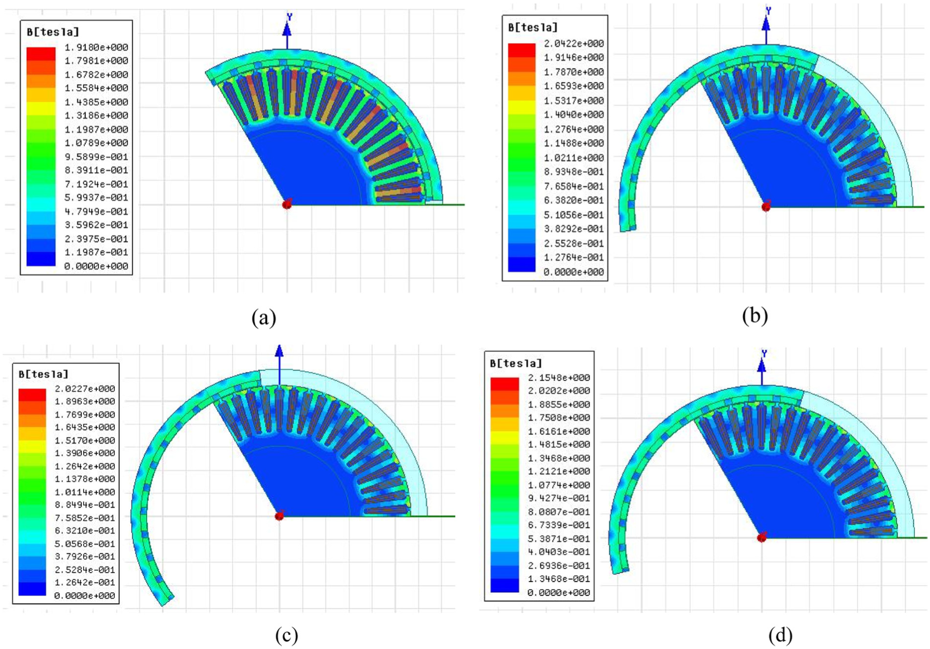
Magnetic flux density in (a) 0 s, (b) 0.014 s, (c) 0.02 s, and (d) 0.04 s at starting of the load.
Figure 11 shows the magnetic field strength when the time period is 0, 0.014, 0.02, and 0.04 s after the starting of the load. As shown in Figure 11, when the in-wheel motor starts, the magnetic field strength between the permanent magnet and the stator teeth is moderately high. Yet, when the operation continues, it becomes stable. In general, the value of magnetic field strength in the internal position of the in-wheel motor is fixed, the same as magnetic induction density distribution.

Magnetic field strength in (a) 0 s, (b) 0.014 s, (c) 0.04 s, and (d) 0.02 s at starting of the load.
Magnetic lines in 0, 0.014, 0.02, and 0.04 s since the in-wheel motor was started up in loading state are shown in Figure 12. The change of magnetic lines is as well in periodic form. It appears to be more intensive in the area where the magnetic field is relatively strong, and it is consistent with the distribution pattern of magnetic line.

Magnetic lines in (a) 0 s, (b) 0.014 s, (c) 0.02 s, and (d) 0.04 s at starting of the load.
Analysis of start-up characters of in-wheel motor
In order to further analyze the start-up characters of in-wheel motor, the change in phase current and torque should be considered, as shown in Figures 13 and 14.

Change in the in-wheel motor phase current.

Change in the in-wheel motor torque.
It can be seen in Figure 13 that the winding of the in-wheel motor is divided into three phases, including phase A, phase B, and phase C. In Figure 13, the red one represents the current phase A, brown one current phase B, and blue one current phase C. Observed individually, phase A is the fastest, followed by phase B, and phase C is the slowest. Generally speaking, the tendencies of all those three phases are unanimous, which meet the requirements of the design.
The change in the in-wheel motor torque is shown in Figure 14, which illustrates the fact that negative torque results from the direction of the torque. Before 5 ms, the in-wheel motor starts up, so the change in torque is relatively large and shows a longitudinal symmetry. The peak can reach 170 Nm during this period. Between 5 and 15 ms, the range of its change goes down and fluctuates in a given interval, giving a sign of being stable. However, after 15 ms, the torque becomes relatively stable, fluctuating between −10 and 6 Nm. During this time, the averages are unaffected, maintaining at 35 Nm, which meet the requirement of the design.
Comparison between the results of simulation analysis and designed calculation
According to the analysis in Ansoft Maxwell software and calculation in the previous section, data are obtained and contrasted in Table 3, and the main technical parameters of the in-wheel motor are determined in Table 4.
Comparison between the results of simulation analysis and design calculation.

Main technical parameters of in-wheel motor.

As shown in Table 3, the results are acceptable although the error exists. Due to some inevitable error between software computing and designed calculation, and the two-dimension simulation is adopted in the analysis of in-wheel simulation, not kept with the real three-dimension model incompletely, the results of two methods are not exactly the same. In addition, the outer rotor in-wheel motor designed in this article does not affect greatly the overall in-wheel motor design of micro-electric vehicle. Based on the design calculation of the in-wheel motor electromagnetic structure and the simulation analysis of the in-wheel motor electromagnetic properties, we can determine the final design of the main technical parameters of the in-wheel motor, as shown in Table 4.
Conclusion
According to the theory of electromagnetic field and the working principle of electric machine, the outer rotor in-wheel motor of micro-electric vehicle is designed and its electromagnetic design is carried out. The outer rotor stator size and related parameters are determined by mathematical formula, and the analysis model is established.
The two-dimensional simulation dynamic model of in-wheel motor is established. By the electromagnetic strength and operating performance at different times, the change situation of magnetic flux density, magnetic field strength, and magnetic line of force is obtained as the in-wheel motor is working. The results show that all of them have certain rules and are subjected to periodic variation.
The starting condition of the in-wheel motor is simulated, and its operating characteristic curve is obtained. The main technical parameters of in-wheel motor are determined, and the final simulation analysis results are in good agreement with the design calculation results, which prove that the design scheme is reliable and accurate. It is cost-effective and a faster way to design the in-wheel motor, which provides a solid theoretical basis for the restudy of the outer rotor in-wheel motor.
Footnotes
Acknowledgements
The authors would like to thank the encouragement of the editor and the anonymous reviewers for their helpful comments and suggestions to improve the manuscript.
Handling Editor: Yangmin Li
Declaration of conflicting interests
The author(s) declared no potential conflicts of interest with respect to the research, authorship, and/or publication of this article.
Funding
The author(s) disclosed receipt of the following financial support for the research, authorship, and/or publication of this article: This research was supported by the National Natural Science Foundation of China (grant no. 51565011), the Natural Science Foundation for Distinguished Young Scholars of Jiangxi Province (grant no. 20171BCB23059), the Key Research Program of Jiangxi Province (grant no. 20171BBE50039), the Natural Science Foundation of Jiangxi Province (grant nos 20171BAB216027 and 20171BAB216 029), and the Foundation of Communications Department of Jiangxi Province (grant no. 2015D0065).