
Abstract
Based on the bionic non-smooth surface theory, this article carries out (1) design of the structure of bionic non-smooth sealing rings and toothed bars of the sealing structure and (2) finite element simulation study on the bionic non-smooth surface structure of roller-cone bits. The result shows that (1) when the parameter Y is equal to the rack angles, the maximum pressure of the Type B is smaller than that of the Type A, while the equivalent stress of the Type A is smaller than that of the Type B; when the parameter Y is equal to the tooth distribution, the maximum pressure and the equivalent stress of the rack angle of 30° are smaller than that of the rack angle of 20°; and when the rack angle is equal to the tooth distribution, the maximum contact pressure and the equivalent stress of the tooth decrease with the increase in the parameter Y. (2) Compared with the O-shaped sealing rings, the new tooth bars avoid the problem of over-large contact area. (3) The grid-shaped sealing structure can increase the wear resistance of rubber rings and delay their wear and aging, thus improving their service life.
Introduction
Roller-cone bit is the most important tool of rock breaking in drilling engineering, the working performance of which directly affects the drilling quality, efficiency, and cost.1,2 The service life of the bearing system is one of the key factors that affect the service life of a roller-cone bit, while the service life of the bearing system is largely dependent on the service life of the sealing rings. Figure 1 is the assembly diagram of the bearing seal of a high-speed roller-cone bit. As shown in Figure 1, the sealing system is located in the seal cavity, which is formed by claw bearing and the inner hole of the roller cone.

Assembly diagram of bearing seal of a roller-cone bit.
Figure 2 is the detail of the seal shown in Figure 1. The traditional sealing system is a typical bimetallic floating sealing structure adopted by the roller-cone bits, which is located at the root of the tooth palm bearing. The traditional sealing system consists of a pair of metal rings and a pair of rubber energy-supply rings, which has the feature that the axial seal is formed by a high-precision metal sealing ring, and the radial seal is implemented by two highly flexible O-shaped rubber rings which are made of nitrile butadiene rubber (NBR). The O-shaped rubber rings are located in the sealing area of palm and the roller cone, respectively, which ensure the sealing surface of these two metal sealing rings can always be in good contact, so as to achieve the reliable seal.

Detail of the seal.
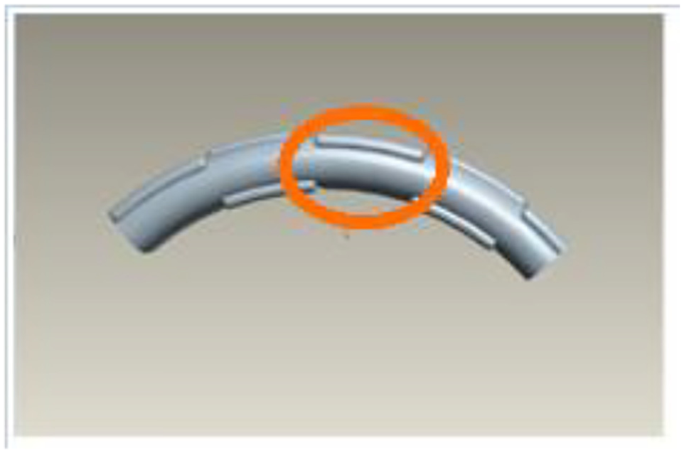
However, by analyzing of the failed bimetallic sealing structure collected on site, the major factor of the failure is the wear of rubber rings, as shown in Figures 3 and 4. 3 It not only reduces the service life of bearing, resulting in rapid failure of the entire drilling bit, but also causes frequent replacement of the drilling bit, which reduces drilling efficiency and increases the cost.

Detail of the rubber ring wear on dynamic metal ring (100×).

Detail of the rubber ring wear on static metal ring (50×).
In order to overcome the shortcomings of the traditional sealing system, researchers at home and abroad have carried out the studies on sealing structure. In the early 1990s, MS Kalsi, a US expert in sealing, and the security company jointly launched a hydrodynamic seal bearing bits, opening up a new chapter of the development of radial sealing technology. 4 In 2003, Professor Qiming Yang et al. from Southwest Petroleum University put forward a saucer-shaped sealing ring from the structural design of reducing the contact pressure. The new designed sealing ring is featured by high sealing performance, stability, and strong resistance against friction and wear. Meanwhile, the new structure has the wipe function under dynamic load, so as to prevent the intrusion of abrasives. 5 In 2005, the Baker Hughes company introduced a high-speed roller-cone bit with single metal floating seal (SEMS). The service life of such type in the Gulf of Mexico is over 55 h. The back-supporting rubber rings were added to the SEMS. 6 In 2006, Jian Sun et al. analyzed the sealing performance of the floating surfaces of high-speed drilling bits using the finite element method. The deformation and contact stress of the structure under different assembly conditions and working conditions were simulated. An analysis of the problems during the actual use was carried out based on the comparison of the result, which served as a guide for similar sealing structures of floating surfaces and enabled further studies on the mechanism of the sealing of floating surface. 6 The Smith, Hughes, and Reed companies, which are the leading producers of roller-cone bits in the world, jointly developed Smith bearing system. According to Smith, the adopted O-shaped sealing ring is made of highly saturated NBR, which is 58% higher than the standard butadiene nitrile rubber in wear resistance, 74% in tensile strength, and 25% in heat resistance. The cross section on the sealed box is concave, which is better than the cylindrical shape in limiting the twisting and moving of O-shaped rings. 7
In terms of the study on bionic non-smooth surfaces, LQ Ren designed and made the non-smooth surfaces of bulldozer blades by simulating the surfaces of cockroach heads in 1995. The result showed that the reduction in resistance of the non-smooth blades was 13.02% in average less than that of traditional (smooth) blades of bulldozer. The reduction in resistance of an optimal blade can reach 18.09%. 8 Then, he carried out the researches in 2003 and 2007 on animals such as cockroaches and ants. He tried to find out the mechanism through which some body parts of those soil animals could be coated with no mud with their geometric non-smooth structure. He also studied the non-smooth surfaces and anti-adhesion effect of several typical foliages and designed similar bulldozer blades with non-smooth surfaces.9,10 Yang et al. 11 carried out researches on the high-temperature features in friction and wear of W9Cr4V high-speed steel concave bionic non-smooth surfaces after laser processing. L Xu et al. 12 developed a new type of bionic plow after obtaining the information of the three-dimensional (3D) geometric surfaces of boar heads. K Gao et al. 13 designed the bionic diamond drilling bits based on the non-smooth theory of the dung beetle head, thus to increase the speed and service life of drilling bits. JZ Lu et al., 14 through such procedures as laser processing to develop 0Cr18Ni9, a type of stainless steel with bionic non-smooth grid-shaped structure, significantly improving such mechanical features as stiffness, surface residual stress, and wear resistance. Xu et al., 15 took the sealing ring of the oil cylinder as the research object, studied the correlation between piston velocity, bionic concave diameter, and the friction reduction feature.
The above researchers carried out a large number of studies on the theories of bearing sealing structure of drilling bits and bionic-non-smooth surfaces, producing fruitful research results. However, there is little research on the sealing structure of the bionic non-smooth surfaces of drilling bits. Therefore, start with the optimization of the sealing structure of drilling bits, the bionic non-smooth surface theory is introduced, so as to reduce the contact area of rubber rings and improve their wear resistance.
Design of the sealing structure of grid-shaped bionic non-smooth sealing rings
Ontological design of sealing structure
Design of inside diameter
On the basis of the design of existing drilling bits, and according to the parameter design of the structure, the bionic non-smooth sealing structure of drilling bills is set, in which the bearing diameter is 50 mm, as shown in Figure 5. Since the rotary sealing rings contract with heat rather than expanding under tension, the Karl–Joule effect is generated. Therefore, sealing rings with smaller compression ratio should be considered, and the inside diameter must be slightly larger than the shaft diameter (about 3%–5%) to avoid the rotation of the sealing rings. As a result, the inside diameter of the sealing rings is 51.5–52.5 mm. In this finite element analysis, the adopted inside diameter d = 52 mm.
Bearing.
Design of compression ratio
Compression ratio refers to the ratio between the compression set of the cross-sectional diameter of sealing rings and the cross-sectional diameter under uncontrolled conditions. It is a relative value and irrelevant to the cross-sectional diameter. The cross section of the rubber sealing rings must be provided with a certain compression ratio so that the rings can be resilient enough. As shown in Figure 6, ε refers to compression ratio

where ε is the compression ratio of O-shaped ring, h is the distance from the bottom to the sealing surface of O-shaped ring, and d0 is the cross-sectional diameter of O-shaped ring

Compression ratio of sealing ring.
The sealing performance of sealing rings is related to the compression ratio. In general, the compression ratio increases with the increase in the sealing pressure. However, the compression ratio should be limited within an appropriate range. If the compression ratio is excessively small, the contact stress on the sealing surfaces cannot meet the requirement of sealing effectiveness, and the sealing performance cannot be guaranteed. Similarly, an over-large compression ratio will cause an over-large compression set, and the sealing rings will be not resilient enough, the effectiveness cannot be guaranteed, and finally become invalid for a long period.
As shown in Figure 7, the compression ratio ε of the outside diameter of sealing rings d0 is an important parameter to measure sealing performance and service life of sealing rings. It is expressed by the following formula
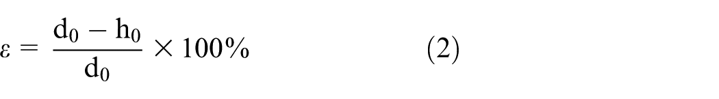
where d0 is the cross-sectional diameter of the O-shaped rings under uncontrolled condition in mm; h0 is the distance from the bottom of notch to the sealing surface of the O-shaped ring, which is the cross-sectional height of the O-shaped rings in mm.

O-shaped sealing ring.
The major factors for selecting the compression ratio of O-shaped sealing rings are as follows:
Provide enough contact pressure on sealing surfaces;
Friction should be as small as possible;
Avoid permanent distortion.
A basic indicator to measure and assess sealing performance is the contact pressure on sealing surfaces. This pressure should be higher than the working mediator pressure so as to guarantee the sealing performance.
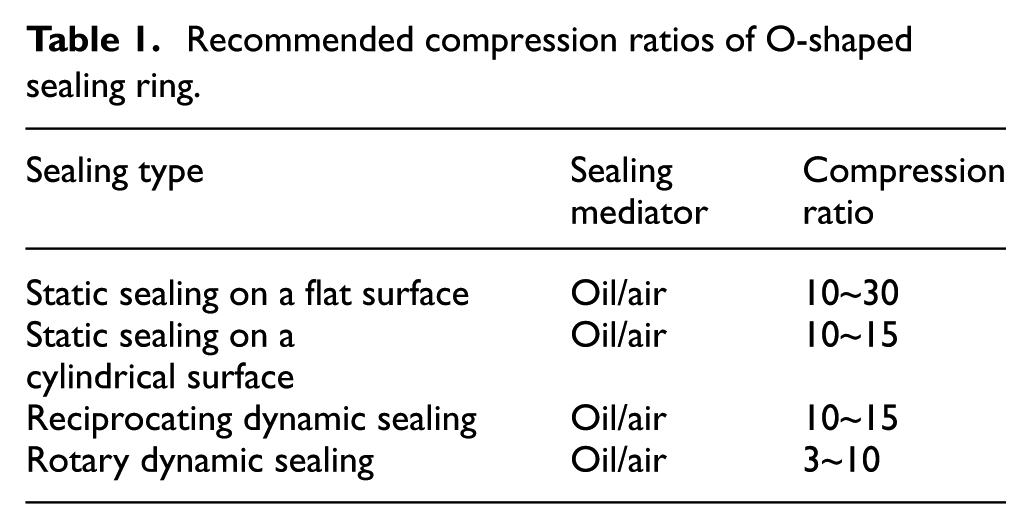
Similarly, as the materials used in the simulation study are the same as the material used by the O-shaped sealing rings of roller-cone bits, the compression ratio of the O-shaped sealing rings can be used to determine the compression ratio of the sealing structure of bionic non-smooth surfaces. Considering all the factors above, the compression ratios of the sealing performance of bionic non-smooth surfaces of roller-cone bits in ANSYS finite element analysis are presented in Table 1. The values selected not only guarantee the sealing effectiveness but also avoid over distortion of O-shaped sealing rings.
Recommended compression ratios of O-shaped sealing ring.
Design of cross-sectional diameter and outside diameter
The selected compression ratio is set as 10% and then according to the compression ratio formula (2), the outside diameter of bionic non-smooth sealing structure is
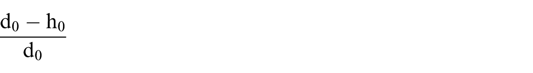
where d0 is the cross-sectional diameter of the sealing structure of bionic non-smooth surfaces under uncontrolled condition in mm; h0 is the distance from the bottom of notch to the sealing surface of the O-shaped ring, which is the compressed cross-sectional height of the bionic non-smooth sealing structure in mm.
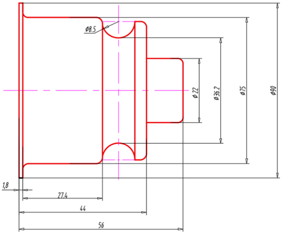
As shown in Figure 8, the shaft diameter is 50 mm, and the hole diameter is 60 mm, so h0 is equal to 5 mm. Moreover, according to the compression ratio formula, the cross-sectional diameter d0 ≈ 5.55 mm. The outside diameter D = d + 2 × d0; for easy calculation, d0 = 6 mm and D = 64 mm.
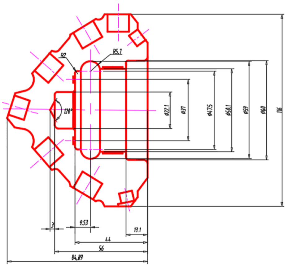
CAD of roller cone.
Tooth-shaped design of sealing structure
The key laboratory of ministry of education for bionic technology for ground machines in Jilin University carried out a special study on the system of reducing adhesion and friction of non-smooth surfaces for soil animals, and defined and categorized the non-smooth surfaces of soil animals.16–18 One kind of them was defined as geometric non-smooth surfaces, which includes convex shape, concave shape, ribbed shape, wavy shape, grid shape, and scale shape. A taxonomic study on the shape of geometric non-smooth surfaces of several typical soil animals was also carried out. As shown in Figure 9, the size of structural unit, distribution, and mechanical features were analyzed in detail and systematically discussed the mechanism of reducing adhesion and friction of soil animals. The results showed that, though the animals may have convex, concave, or scaled surfaces, the cross sections of them are wavy with different forms and finally can help reduce the contact area and adhesion, as well as decrease friction. 19

Shapes of geometric non-smooth surfaces of animals: (a) ant’s body surface, (b) elytron of carabidae, (c) chest of dung beetle, and (d) head of dung beetle.
Based on the relevant theories and experiment results of the existing references, the grid shape is chosen for the tooth-shaped design.
The leaking of grease and contact area should be taken into consideration in terms of the grid-shaped toothed bars design. Because of the interlaced distribution of grids, more grease can be left and saved in the space between the toothed bars and can avoid the over-large contact area in O-shaped rings. In addition, the space between the toothed bars can be used for cooling and reducing the contact area. In this way, some grease can be saved to reduce friction, decrease the working temperature of rubber rings, increase the wear resistance, slow down the wear and aging of rings, and prolong their service life.
According to the above-mentioned ontological design of the sealing structure, the parameters of grid-shaped toothed bars are designed based on the contact cross section with a diameter of 5 mm, and the radius of toothed bars R = 0.8 mm, as shown in Figure 10.

Cross section of grid-shaped toothed bar.
First of all, because the parameters of grid-shaped toothed bars are designed based on the cross section with a diameter of 5 mm, the number of lines of toothed bars should be limited. As shown in Figure 11, two lines of toothed bars are designed at the inside and outside of the cross section.

Grid-shaped toothed bars.
As shown in Figure 12, parameter Y, which is the vertical distance between two toothed bars, is designed based on the cross-sectional design. The distribution and distance of toothed bars on cross section are affected by parameter Y. An over-large parameter Y cannot achieve the sealing, while an over-small parameter Y makes the two toothed bars on the same side affect each other. Therefore, parameter Y is set to be 2.4, 2.6 and 2.8 mm in the simulation.
Length of toothed bars.
Second, as the orange area shown in Figure 12, the length of toothed bars cannot be designed on flat surface. Therefore, the length of toothed bars is designed according to angle (°) rather than length (mm), as shown in Figure 13. The angle of toothed bars influences the number and distribution of toothed bars. Therefore, the length should not be too long or too short. In the simulation study, 20° and 30° angles of toothed bars are chosen for design.
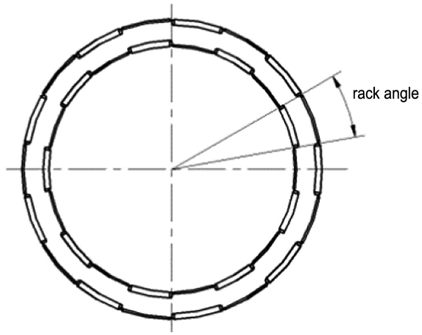
Angle of toothed bar.
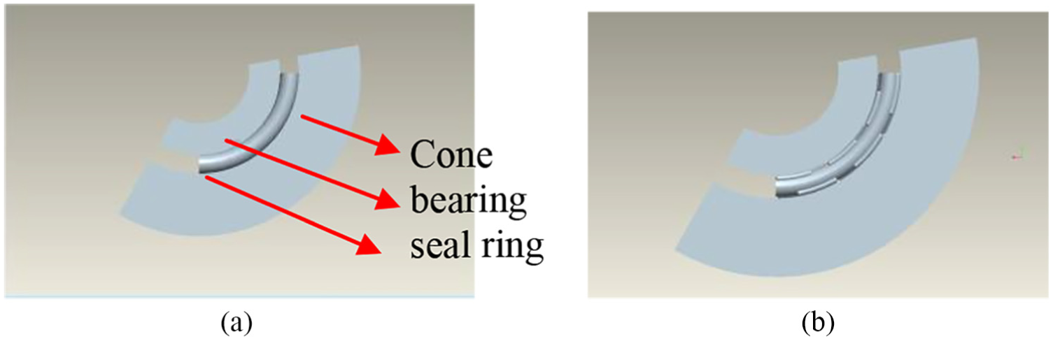
Finally, the setting of grid-shaped toothed bars includes fully interlacing distribution (Type A) as shown in Figure 14(a) and partially interlacing distribution (Type B) in Figure 14(b).

Distribution of grid-shaped toothed bar: (a) fully interlacing and (b) partially interlacing.
Fully interlacing distribution means that the two toothed bars at the same side adjacent to each other will not intersect, while partially interlacing distribution means some parts of the two toothed bars on the same side adjacent to each other will overlap.
In terms of the length of toothed bar with an angle 20°, the two different distributions are shown in Figure 15.

Grid-shaped sealing ring with a toothed bar angle 20°: (a) partially interlacing distribution and (b) fully interlacing distribution.
Similarly, for the length of toothed bar with an angle 30°, the partially interlacing and fully interlacing distributions are shown in Figure 16.

Grid-shaped sealing ring with a toothed bar angle 30°: (a) partially interlacing distribution and (b) fully interlacing distribution.
The number of grid-shaped toothed bars is determined by the above three parameters. From the three parameters, the structure data of grid-shaped sealing rings in the simulation are shown in Table 2.
Parameter of grid-shaped sealing ring structure.

Simulation of bionic non-smooth surface structure of roller-cone bits
Geometric models establishing
The geometric models of bionic non-smooth sealing rings are built with professional computer-aided design (CAD) software Pro/Engineer. 20 For easy applying the load and displacement, and convenient for observing the displacement and equivalent stress of the sealing rings, 1/4 model is established in the software. The modeling includes three parts: the shaft diameter, the roller bearing, and the bionic non-smooth sealing rings. To avoid the overflow of the sealing rings and uneven force when displacement and load are applied, 1/3 model is adopted to build the simplified models of shaft diameter and roller bearing. The two contact surfaces are just contacted with each other.
The simplified models of O-shaped sealing rings and grid-shaped sealing rings are built, respectively, in Pro/Engineer, as shown in Figure 17.
Simplified model: (a) O-shaped sealing ring and (b) grid-shaped sealing ring.
Definition of the property of materials
The establishment of model materials includes the metal material property definition of shaft diameter and roller bearing, together with the material property definition of bionic non-smooth sealing ring, as shown in Table 3.3,21 The 9CrW18Mn metal material is adopted, which is the isotropic elastomeric material of linear elastic materials. The material property of bionic non-smooth sealing rings is directly defined as the material of O-shaped sealing rings, which is the NBR.22–24 The working temperature of NBR is generally between −30°C and 120°C and the elasticity modulus is between 2 and 5.5 MPa. In addition, the definition of sealing ring material property also includes the parameter setting of linear elastic materials and hyper-elastic materials. The parameter setting of linear elastic materials chooses isotropic elastomeric materials, and the parameter setting of hyper-elastic materials uses Mooney–Rivlin. The parameters include C10 (7.2668 MPa), C01 (−4.587 MPa), C20 (3.353 MPa), C11 (−2.187 MPa), C02 (0.6986 MPa), and d = 0.001.
Material parameters.
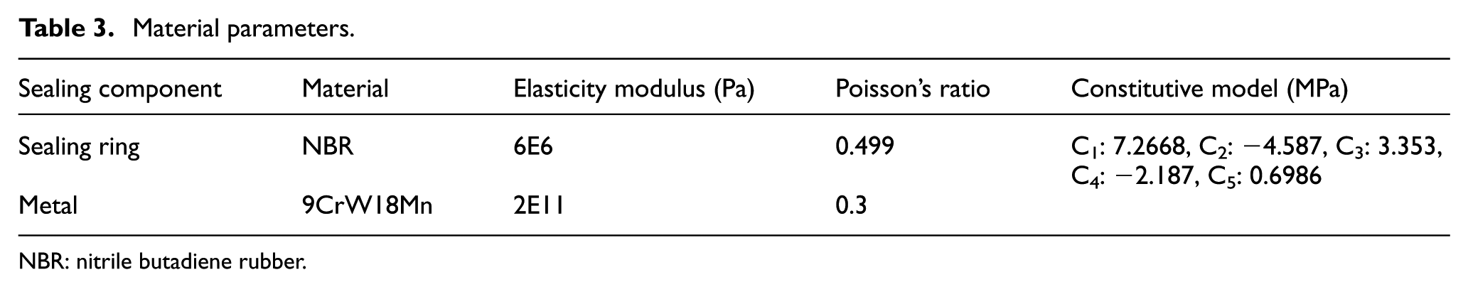
NBR: nitrile butadiene rubber.
Definition of cell property
Solid185 is adopted as the cell property, which is shown in Figure 18.25,26 The cell is mainly used to construct the 3D solid structure. The cell is defined through eight nodes and each node can shift toward three directions, that is, X, Y, and Z. The cell has the abilities of hyper elasticity, stress stiffness, creep deformation, large deformation, and strain. Meanwhile, the hybrid mode is employed to simulate the almost incompressible elastoplastic materials and incompressible hyper-elastic materials.
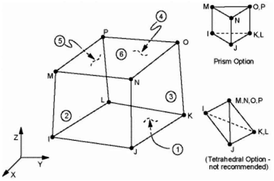
Solid185 cell.
Dividing grids
Grids are divided on the models corresponding to the two materials. In terms of the metal simplified model of shaft diameter and roller bearing, the grids are 2 mm × 2 mm in size. For the rubber bionic non-smooth sealing rings, the grids are 1.5 mm × 1.5 mm in size. The grids of two contact pairs are 1 mm × 1 mm in size. The grids divisions of the simulation model are shown in Figure 19.

Grid divisions of the simulation model.
Setting contact pairs
Two contact pairs are existed in this simulation. One contact pair is roller cone and bionic sealing ring, as shown in Figure 20(a). Another pair is bearing and bionic sealing ring, as shown in Figure 20(b).

Contact pair: (a) contact between roller bearing and bionic sealing ring and (b) contact between shaft diameter and bionic sealing ring.
Applying displacement and load
The load applying of the bionic non-smooth sealing rings simulation analysis can be divided into assembly process and working process. During the assembly process, the load applying is achieved through the relative displacement between the simplified models of the shaft diameter and roller bearing. For the working process, the load is applied through exerting pressure on the models. First, during the assembly process, according to d0 = 5 mm and h0 = 6mm, the displacement is 1mm, as shown by the red arrow in Figure 21. When displacement is applied, the shaft diameter is set to be fully constraint (totally fixed), as shown by the purple area in Figure 22. A relative movement is formed through the displacement of roller bearing and then displacement load is exerted.

Displacement direction.

Fully constraint bearing.
In reality, the differential pressure between the internal and external is generally 0.3–0.5 MPa, and the measured maximum value under the shaft is 0.7 MPa. Therefore, to guarantee the reliability of sealing (keep the outside mud out of seal cavity) and avoid leaking of grease inside of the seal cavity, the maximum contact pressure on the sealing surface should be greater than the differential pressure between the internal and external of the seal cavity. Here, the differential pressure is set as 1 MPa during the working process. Because the bearing is set to be fully restraint when applying the displacement load, the pressure can only be added to the roller cone. Therefore, the red part of cone in Figure 23 is chose to be applied the pressure.

Exerting pressure.
Due to the main body structure design and the assembly method of the grid-shaped sealing ring is in line with the O-shaped sealing ring, the load of the grid-shaped sealing ring is applied in the same way.
As mentioned before, the wear resistance of the designed bionic non-smooth surface sealing ring is reflected by the contact pressure and the equivalent stress. The higher the contact pressure and the larger the equivalent stress, the serious the abrasion is, accordingly the wear resistance is lower and the service life is shorter. Moreover, the sealing ring will be damaged once the contact pressure is beyond the allowed range. Therefore, in the condition of guaranteeing the valid seal (i.e. the contact pressure and the equivalent stress are equal or greater than the allowable pressure/stress), the contact pressure and the equivalent stress are the smaller the better to achieve the goal of improving the wear resistance.
Contact pressure analysis
Contact pressure of grid-shaped tooth
For the convenience of observing and analyzing, three groups of experiments with different Y values are carried out.
Group 1: the contact pressure analysis for Y = 2.4 mm. The results are shown in Figure 24.

The grid-shaped contact surface when Y = 2.4 mm: (a) contact surface between W2.4/20°-A and the bearing, (b) contact surface between W2.4/20°-A and the roller cone, (c) contact surface between W2.4/20°-B and the bearing, (d) contact surface between W2.4/20°-B and the roller cone, (e) contact surface between W2.4/30°-A and the bearing, (f) contact surface between W2.4/30°-A and the roller cone, (g) contact surface between W2.4/30°-B and the bearing, and (h) contact surface between W2.4/30°-B and the roller cone.
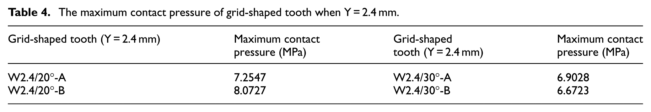
As shown in Figure 24, the contact pressure distribution of each model is similar, which is mainly concentrated on the toothed racks, and the maximum pressure occurs on the end face of toothed racks. Table 4 shows the maximum contact pressure of these four types of grid-shaped tooth, which are 7.2547, 8.0727, 6.9028, and 6.6723 MPa. It is clear that the maximum contact pressure of W2.4/30°-B is the smallest among all the four groups.
The maximum contact pressure of grid-shaped tooth when Y = 2.4 mm.
Group 2: the contact pressure analysis for Y = 2.6 mm, the results are shown in Figure 25.

The contact surface of grid-shaped tooth when Y = 2.6 mm: (a) contact surface between W2.6/20°-A and the bearing, (b) contact surface between W2.6/20°-A and the roller cone, (c) contact surface between W2.6/20°-B and the bearing, (d) contact surface between W2.6/20°-B and the roller cone, (e) contact surface between W2.6/30°-A and the bearing, (f) contact surface between W2.6/30°-A and the roller cone, (g) contact surface between W2.6/30°-B and the bearing, and (h) contact surface between W2.6/30°-B and the roller cone.
As shown in Figure 25, the contact pressure distribution of each rack is also roughly similar, which is concentrated on the rack. Table 5 shows the maximum contact pressure of the four types of grid-shaped tooth, which are 7.1094, 5.406, 6.6477, and 5.3119 MPa. Therefore, in this group of grid-shaped tooth, the maximum contact pressure of the W2.6/30°-B has the smallest value.
The maximum contact pressure of grid-shaped tooth when Y = 2.6 mm.

Group 3: the maximum contact pressure analysis for Y = 2.8 mm, the results are shown in Figure 26.

The contact surface of grid-shaped tooth when Y = 2.8 mm: (a) contact surface between W2.8/20°-A and the bearing, (b) contact surface between W2.8/20°-A and the roller cone, (c) contact surface between W2.8/20°-B and the bearing, (d) contact surface between W2.8/20°-B and the roller cone, (e) contact surface between W2.8/30°-A and the bearing, (f) contact surface between W2.8/30°-A and the roller cone, (g) contact surface between W2.8/30°-B and the bearing, and (h) contact surface between W2.8/30°-B and the roller cone.
Similar to the aforementioned two groups, the contact pressure distribution of each rack is also concentrated on the rack. Table 6 shows the maximum contact pressure of the four types of grid-shaped tooth. It can be seen that the grid-shaped tooth with Y = 2.8 m, W2.8/30°-B has the smallest maximum contact pressure, which is 5.6001 MPa. While the W2.8/30°-A has the peak value which is as large as 5.6001 MPa. Therefore, when the parameter Y and the rack angle are fixed, the maximum contact pressure of the Type B is smaller than that of the Type A.
The maximum contact pressure of grid-shaped tooth when Y = 2.8 mm.

As is indicated in the above three sets of data, when Y is equal to the rack angle, the maximum pressure of Type B is smaller than that of Type A; when Y is equal to the tooth form, the maximum pressure of the rack angle of 30° is generally smaller than that of the rack angle of 20°. Meanwhile, it can be seen from Table 7 that the maximum contact pressure of the tooth decreases with the increase in the Y when the rack angles and the tooth form distribution are the same.
The maximum contact pressure of 12 types of grid-shaped teeth (MPa).

As mentioned before, the differential pressure of assembly work in this simulation is set as 1 MPa. The differential pressures of the 12 types of grid-shaped tooth are all greater than 1 MPa. Therefore, these grid-shaped teeth satisfy the conditions of sealing.
Contact pressure analysis of O-shaped sealing rings
The contact pressure distributions of O-shaped sealing rings are presented in Figure 27. The largest contact pressure (3.2432 MPa) occurring on the contact surface of both sides.
The contact pressure of the O-shaped sealing ring.
Contrastive analysis of the contact pressure
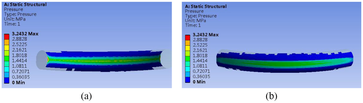
On account of the contact pressure is the smaller the better when satisfying the sealing condition. Here the new type tooth with the smallest maximum contact pressure is compared with the O-shaped sealing ring. The grid-shaped tooth W2.8/30°-B is selected. The contact pressures of these two types of teeth are shown in Figure 28.

Comparison of the O-shaped sealing ring and the grid-shaped tooth: (a) W2.8/20°-B and (b) O-shaped sealing ring.
It can be conclude from Figure 28, the maximum pressure of the grid-shaped and O-shaped teeth occurs on both ends of the contact surface. The largest pressure of the grid-shaped profile occurs on both ends of the rack angles. The maximum contact pressures of these two models are 3.9069 and 3.2432 MPa, respectively.
Furthermore, Figure 29 shows that the contact area of the grid-shaped tooth profile is obviously smaller than that of O-shaped sealing ring. Therefore, the oversize contact surface of the O-shaped sealing ring has been improved by the new design. In conclusion, though the W2.8/30°-B can hardly lower the contact pressure, it can effectively reduce the contact surface.

The contact status of the two models: (a) W2.8/20°-B and (b) O-shaped sealing ring.
Equivalent stress analysis
Equivalent stress analysis of grid-shaped tooth
Similar to the contact pressure analysis of grid-shaped tooth, for the convenience of observation and analysis, different groups are divided based on the value of parameter Y for the equivalent stress analysis of grid-shaped tooth.
Group 1: the equivalent stress for Y = 2.4 mm, the results are shown in Figure 30.
The equivalent stress of the grid-shaped tooth when Y = 2.4 mm: (a)W2.4/20°-A, (b) W2.4/20°-B, (c) W2.4/30°-A, and (d) W2.4/30°-B.
From Figure 30, the equivalent stress of the grid-shaped tooth structure is concentrated on the rack angles. The equivalent stress is not only influenced by the distribution of grid-shaped tooth forms (completely or partially interlacing distributions) and the angles of the rack (20° or 30°) but also varies among the adjacent tooth racks on the same side, and the inside and outside of the tooth racks. Therefore, the maximum stress of four groups of grid-shaped tooth can be found in Table 8, in which the maximum equivalent stress of the W2.4/20°-A is the smallest.
The maximum stress of the grid-shaped tooth when Y = 2.4 mm.

By further enlarging the red-colored area as shown in Figure 31, it can be seen that the local stress concentration arises at end of the rack. However, the stress mainly focuses on the rack, which has little effect on the cross section of the enlarged area.

The red-colored enlarged areas of the grid-shaped tooth: (a) W2.4/20°-A, (b) W2.4/20°-B, (c) W2.4/30°-A, and (d) W2.4/30°-B.
Further analysis on the impact of the rack distribution on the equivalent stress of the non-contact surfaces is shown in Figure 32. Racks of the Type A are partially interlacing distribution, while the racks of Type B are completely interlacing distribution. The space between the adjacent racks of the Type A is therefore narrower than that of the Type B. For racks of Type A, the influence area of equivalent stress on the adjacent racks is greater than the adjacent racks of the Type B, which shows more stress distributed on the non-contact surface than racks of the Type B. In the case where the distributions of the tooth forms are the same, but the angles of racks are different, the sizes of the rack angles and influence area of the equivalent stress on the non-contact surface are irrelevant with each other, although seemingly the smaller the angles are, the large number of racks may be.

The grid-shaped non-contact surface: (a) W2.4/20°-A, (b) W2.4/20°-B, (c) W2.4/30°-A, and (d) W2.4/30°-B.
Group 2: the equivalent stress for Y = 2.6 mm, the results are shown in Figure 33.

The equivalent stress of the grid-shaped tooth when Y = 2.6 mm: (a) W2.6/20°-A, (b) W2.6/20°-B, (c) W2.6/30°-A, and (d) W2.6/30°-B.
Figure 33 shows that the equivalent stress distribution of Group 2 is similar to that of Group 1. It can be seen from Table 9 that the maximum equivalent stress of the four models are 3.1717, 3.0052, 3.5829, and 3.5148 MPa. Therefore, in this group of grid-shaped tooth, the maximum equivalent stress of the W2.6/20°-B is the smallest.
The maximum equivalent stress of the grid-shaped tooth when Y = 2.6 mm.

Group 3: the equivalent stress for Y = 2.8 mm, the results are shown in Figure 34.

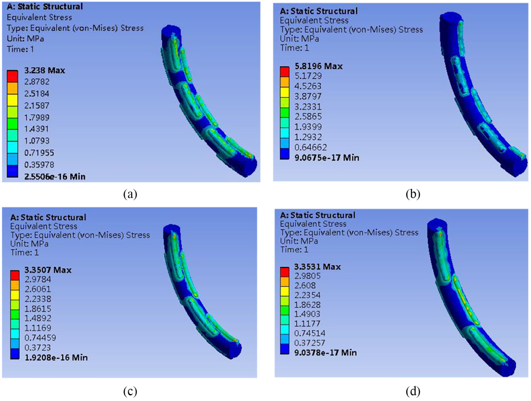
The equivalent stress of grid-shaped tooth when Y = 2.8 mm: (a) W2.8/20°-A, (b) W2.8/20°-B, (c) W2.8/30°-A, and (d) W2.8/30°-B.
As seen in Figure 34, the equivalent stress distribution of Group 3 is similar to that of the above two groups. Table 10 shows that the maximum equivalent stresses of the four models are 2.7565, 2.7373, 2.8882, and 2.9132 MPa. Therefore, in this group of grid-shaped tooth, the maximum equivalent stress of the W2.8/20°-B is the smallest.
The maximum equivalent stress of the grid-shaped tooth.

According to the results of the above three experiments, conclusions can be made that when the parameter Y and the tooth distribution are fixed, the maximum equivalent stress of the rack angle of 20° is generally less than that of the rack angle of 30°; when the parameter Y and the rack angles are fixed, the maximum equivalent stress of the Type A is generally weaker than the maximum stress of Type B; and when the rack angles and the tooth distribution are fixed, the maximum stress decreases with the increase in the parameter Y. The detailed values can be seen in Table 11.
The maximum equivalent stress of the 12 types of grid-shaped teeth.

Equivalent stress analysis of the O-shaped sealing ring
Figure 35 shows the equivalent stress distribution of the O-shaped sealing ring, with the largest equivalent stress (2.7168 MPa) occurring on the cross section of both ends. Compared with the new tooth proposed in this article, the traditional O-shaped sealing ring may have uneven distribution of equivalent stress. However, there is not partially lower equivalent stress occurs on the new tooth. In this regard, the differential pressure of the O-shaped sealing ring is comparatively large.
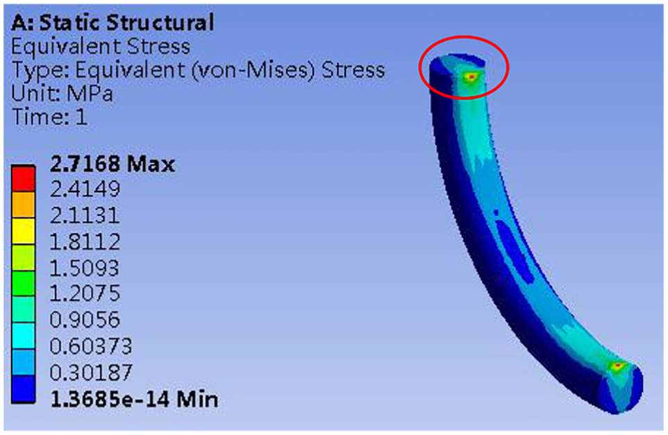
The equivalent stress of the O-shaped sealing ring.
As shown in Figure 36, the equivalent stress of the O-shaped sealing ring is greater in the center toward to direction of the contact surface between the bearing and the tooth rack angle, while the equivalent stress is comparatively small where near the contact surface between the cone and the tooth rack angle. The compression has greater influence on the stress distribution of cross section of the O-shaped sealing rings than that of the grid-shaped tooth.
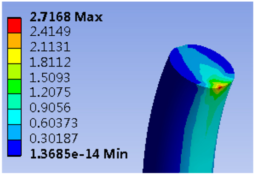
The equivalent stress distribution on the cross section of the O-shaped sealing ring.
Moreover, it is indicated in Figure 37 that the O-shaped sealing ring exerts merely small impact on the non-contact surface.

The non-contact surface of the O-shaped sealing ring.
Contrastive analysis of the equivalent stress
As previously mentioned, the equivalent stress is the smaller the better in condition of satisfying the sealing requirement. Figure 38 shows the equivalent stress comparison of the grid-shaped tooth (W2.8/20°-B) and the O-shaped sealing ring.

The contrastive analysis on the equivalent stress of the grid-shaped tooth and O-shaped sealing ring: (a) W2.8/20°-B and (b) O-shaped sealing ring.
It can be seen in Figure 38, the maximum equivalent stress of two models occurs on both ends of the contact surface. The maximum equivalent stress of the grid-shaped tooth occurs on the junction of the rack angles and other angles. The maximum equivalent stress of the grid-shaped tooth is 2.7373 MPa, while the O-shaped sealing ring is 2.7168 MPa. Compared with the other types of grid-shaped tooth, the W2.8/20°-B has superiority in terms of reducing the pressure and decreasing the deformation. However, it can only reduce the contact area instead of the pressure compared to the O-shaped sealing ring.
Conclusion
To solve the problems as short service life, poor heat resistance, and abrasion resistance of the bearing rings of roller bits, the bionic non-smooth surface theory was introduced to design a new type of sealing ring structure. This new design can optimize the present O-shaped sealing ring, reduce the contact area, retard abrasion and aging of the rubber ring, and extend the service life. Meanwhile, the finite element simulation experiments were conducted to synthetically analyze the contact pressure and equivalent stress. From the experiments results, the conclusions can be made as follows:
The newly designed bionic non-smooth surface sealing structure can effectively avoid oversize contact surface of the O-shaped sealing ring, and the space between the racks are able to dissipate heat and reduce the contact surface. In this way, a certain amount of lubricating oil can be reserved to reduce the resistance, thereby reducing the working temperature, enhancing the abrasive resistance, retarding abrasion and aging, and prolongs service life of the rubber ring.
The regularities of the contact pressure of the grid-shaped tooth are: when the parameter Y is equal to the rack angles, the maximum pressure of the Type B is smaller than that of the Type A; when the parameter Y is equal to the tooth distribution, the maximum pressure of the rack angle of 30° is smaller than that of the rack angle of 20°; and when the rack angle is equal to the tooth distribution, the maximum contact pressure of the tooth decreases with the increase in the parameter Y.
As for the equivalent stress of grid-shaped tooth, with the parameters Y and the tooth distribution fixed, the equivalent stress of the rack angle of 30° is smaller than that of the rack angle of 20°; with the parameter Y and the rack angle fixed, the equivalent stress of the Type A is smaller than that of the Type B; and with similar rack angle and tooth distribution, the equivalent stress decreases with the increase in the parameter Y.
Furthermore, there are some related works that can be done for the following research. For example, the mechanical seal structure would be designed as the square, rectangle, or trapezoid and then the related tooth as well as the distribution should be redesigned and researched.
Footnotes
Handling Editor: Jan Torgersen
Declaration of conflicting interests
The author(s) declared no potential conflicts of interest with respect to the research, authorship, and/or publication of this article.
Funding
The author(s) disclosed receipt of the following financial support for the research, authorship, and/or publication of this article: This research was partially supported by the Young Scholar Development Fund of SWPU (No. 201599010077), the National Natural Science Foundation of China (No. 51405403), and the Fundamental Research Funds for the Central Universities (No. 2682014BR019).