
Abstract
The mathematical model of the contact stress is established based on the theory of Hertz contact with the assumption that the contact of a seal gasket and hubs of collet connectors is cylindrical. The mechanical models of the seal are established separately by sealing theory in the preloading and operating modes, and the relationships between the preload, the contact stress, and the sealing width are obtained. The relationships of structural parameters and the preload are analyzed and verified with finite element simulation and experiments. An experimental system has been designed and experiments have been conducted to verify the analytical models. Finite element simulation results and experimental results agree with analytical ones very well and the differences of the preload and sealing width are acceptable.
Keywords
Introduction
Subsea collet connector is a jumper connection device in subsea pipeline system, as shown in Figure 1. It is handled by remotely operated vehicle (ROV) for connection between wellhead, pipeline terminal, Christmas tree, and pipe manifold. The collet connector works in extremely severe operating environment. In all instances, the connector is subjected to internal high pressure, high temperature, and external low temperature load.1,2 Its reliability depends on the seal performance; therefore, it is important to analyze the seal contact characteristics of the collet connector.

Installation of the subsea collet connector.
Sealing performance of pipeline connectors has been studied extensively, but most of them focus on other points rather than seal contact characteristics. K Kondo et al., 3 K Tenma et al., 4 and M Abid et al. 5 researched on the contact stress and the sealing performance for the bolted flange connections. K Kondo et al. 3 found that the sealing performance with oval ring gasket was better than that of the connection with octagonal ring gasket. K Tenma et al. 4 found that the stress distribution at the contact surfaces depended on the bolting procedure, and octagonal ring gasket shows a better sealing performance than spiral wound gasket. M Abid et al. 5 found that the sealing performance is related to both the internal pressure and transient thermal load. To investigate the box-shaped bolted flange connection, K Tenma et al. 6 and T Sawa et al. 7 analyzed the gasket contact stress distributions and evaluated their sealing performance by finite element (FE) method and experiment without analytic analysis. R Madazhy et al. 8 analyzed the contact stress of the tapered and flat seals and found that of the tapered seal is sufficient and that of flat gasket surface is not. H Zhao et al. 9 investigated the subsea X-tree wellhead connector VX gasket and analyzed theoretical relation between seal contact stress and its structural parameters and operation pressure. Z Wang et al. 10 analyzed the seal characteristics of horizontal collet connector with oval metal ring. F Peng et al. 11 optimized the collet connector locking structure and analyzed the friction influence on the contact surface.
This article will analyze the seal contact characteristics of the collet connector with a lens seal gasket. The seal structure is for the connection of jumpers with the size of 6.625 in under the internal pressure of 34.5 MPa. First, based on Hertz theory, the contact between the seal gasket and the hub can be equivalent to the contact of cylinders and the contact stress mathematical model is established. Second, mechanical models of the seal in the preloading and operating modes are established separately by the sealing theory, 12 and the relationship between the preload, the contact stress, and the sealing width is obtained. Third, in order to examine the sealing performance of the collet connector, contact characteristics of seal gasket subjected to preload and operation pressure are analyzed using FE calculations. Finally, the analytical results are compared with the experimental results to validate the mathematic model. The effect of the contact characteristics on the sealing performance of the collet connector is discussed as well.
Principle of the collet connector
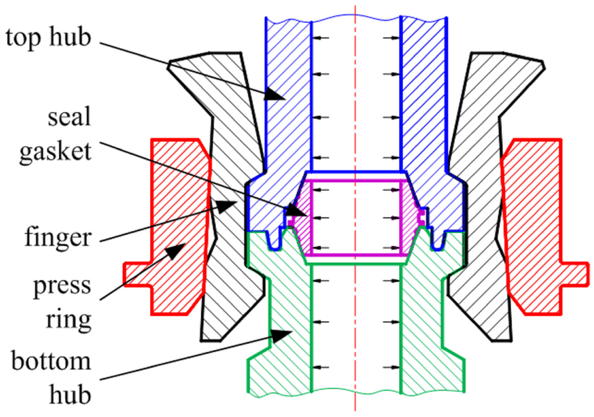
As shown in Figure 2, both of the bottom hub and top hub are dedicated for specific collet connector. Fingers are arranged around the outer surface of the hubs with equal space and work along with the press ring to lock hubs. The bottom hub, top hub, and seal gasket constitute the core of the seal structure in the connector and mate with each other to achieve a seal.
Structure of the collet connector.
In preloading, fingers cooperate with the movement of the press ring and convert the translational motion of the press ring into radial motion of fingers, then strongly hold the hubs and preload the seal. The axial force on the press ring can regulate the sealing preload. In the operation, the high-pressure fluid goes through the inside of the connector, and the high pressure acts on the gasket and hubs. In this case, the self-locking of the friction between the internal conical surface of the press ring and the back surface of the fingers will guarantee that the collet connector has a good seal performance under the subsea static load. The concept of self-energizing seal is that when the internal pressure increases, the sealing performance of the gasket increases automatically without any extra preload. The sealing performance of the self-energizing gasket is not only related to the shape, size, and material of the hubs and gasket, but also related to the medium pressure and preload.
Mechanics of the seal gasket
A metal seal gasket was employed in the seal structure analyzed in this article. When the spherical surface on the seal gasket contacts the conical surface on the hub, it is line contact initially. As the deformations of the seal gasket and hubs increase with the increasing axial load, the contact line turns into a strip in the annular region, which is much less than the dimension of the seal gasket, and the width of this strip is called contact width or sealing width. 13 The sealing width and average contact stress of the contact region are the critical parameters for calculating the preload. And the sealing width and the distribution of the contact stress are indispensable when the sealing performance is discussed. 14 Therefore, analysis on metal seal mechanics is quite necessary, and this article aims to establish analytic equations used in the future engineering design.
Analysis on sealing contact mechanics
It is typically metal-to-metal seal between the seal gasket and hubs. Theoretically, the sealing width has a direct effect on the sealing performance—when the sealing width increases, the traveling distance of the medium along the micro path increases, and the leakage will be reduced.
For non-conforming surfaces in contact at O, as shown in Figure 3, r1 and r2 are the radii of the two bodies, the x-y plane is the common tangent plane of the two surfaces, and the z-axis lies along the common normal line directed positively into Body 2. The undeformed shapes of two surfaces are defined in this coordinates system by the form
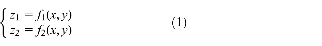
where z1 is the undeformed shape of Body 1; z2 is the undeformed shape of Body 2; f1 and f2 are functions. Therefore, the gap, h, between them before loading can be given by

where f is a function. In the elastic contact with a compression load, each surface is supposed to be topographically smooth on both macro and micro scale. On the macro scale, the profiles of the surfaces are continuous up to their second derivative in the contact region. On the micro scale, it is irregular to disregard small surfaces, which would lead to discontinuous contact or high local variations of contact stress. Thus, the profile of the surface in the contact region of Body 1 close to O can be expressed approximately as

where higher order terms in x and y are neglected; A1, B1, and C1 are positive constants. In the x-y coordinate system, the term of C1xy is zero. Equation (3) can be written as

where

where

where A and B are positive constants; r′ and r″ are principal relative curvature radii. Suppose that (1) the deformation of the sealing contact of the collet connector is elastic, (2) the contact area of each point is a circle, and (3) only the vertical load is applied on the contact surfaces. Thus, it satisfies Hertz theory. In the meantime, as the metal seal of the collet connector is a contact of a spherical surface on a conical surface, seal contact can be equivalent to the contact between a cylindrical body and a plane. The cross section can be simplified into a two-dimensional problem, as shown in Figure 4, which is the limit of an elliptical contact, when r″ is infinite.
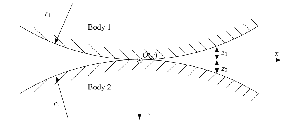
Non-conforming surfaces in contact at O.

Contact principle diagram of the seal gasket.
For the contact of two cylinders,
15

where r is the radius of the spherical surface of the seal gasket, r = r1.
After loading, the elastic displacement (uz) of the points within the contact area is

where d is the displacement of Body 1 after the deformation. Meanwhile, outside the contact area

Differentiate uz with respect of x and yield

As shown in Figure 4, seal half-width is a; the radius of the seal spherical surface is r = 168.148 mm. The materials of the seal gasket and hubs are stainless steel 316 and 12Cr2Mo1, of which the elastic modulus and Poisson’s ratio are E1 = 2.06 × 10⁵ MPa, E2 = 2.1 ×10⁵ MPa, µ1 = 0.25, and µ2 = 0.3. Thus, the equivalent elasticity modulus, E*, can be expressed as

The gradient in the elastic half space due to concentrated normal force, P, is 15

where q is the contact stress due to P; q(x) is the distribution of the contact stress; x′ is the distance between the point in the contact area and O. Plug equation (10) into equation (12) and yield

Equation (13) is a regular integral equation of the first kind, and its general solution 16 is
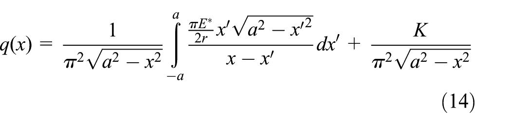
where K is a constant, see Appendix 1.
Equation (14) can be expressed as

where I is a function of x, see Appendix 1.
Substituting K and I into equation (15), the distribution of contact stress can be rewritten as
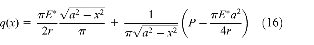
The boundary condition of the contact stress is q(±a) = 0. Solve equation (16) and yield

Plug equation (17) into equation (16) and rewrite the contact stress as
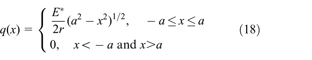
The maximum contact stress is
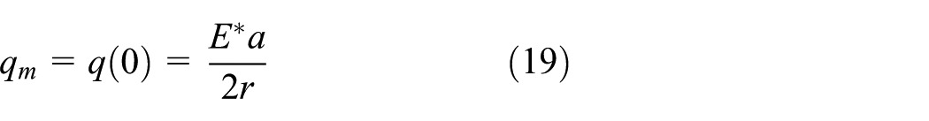
The mean contact stress is

Then the sealing half-width can be described as

Axial preload analysis
The axial preload has a direct effect on the sealing performance of the collet connector. 17 In order to analyze this effect, the process can be divided into preloading mode and operating mode according to the load on the seal gasket. As shown in Figure 5, Dk is the contact diameter, 171.9 mm; α is the angle of the sealing surface, 20°.

Seal structure.
Axial preload of the seal gasket in the preloading mode
In the preloading mode, the seal gasket is compressed by top and bottom hubs from both ends. The compression turns the initial contact line into a strip due to deformation to ensure the reliable sealing performance of the collet connector.
Since the seal is symmetric against the central plane, the analysis of one side is enough. As shown in Figure 6, not only the normal force (N0) but also the friction (f0) of the hubs acts on the gasket in the preloading mode


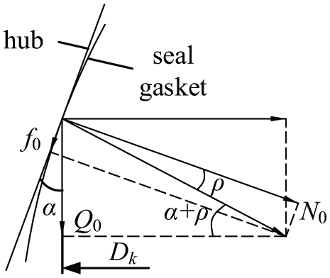
Force of the seal gasket in preloading mode.
The combination of the axial components of N0 and f0 is the preload of the seal gasket, Q0

where ρ is the frictional angle; ρ = arctan(µ) = 8.531° with the steel-to-steel friction coefficient of µ = 0.15.
Axial preload of the seal gasket in operational mode
In the operating mode, the compression of hubs acts on the seal gasket, as well as the pressure produced by the internal medium. Then the axial force on the seal gasket is composed of two components,
First, the internal pressure acts on the surfaces of the gasket and hubs in the gap communicating with internal medium. It will reduce the preload on the spherical surface of the seal gasket and the conical surfaces of the hubs. The axial force produced by the residual preload 12 is

where

where p is the internal pressure (MPa). Thus, the axial force in the operating mode,

Minimum axial preload
The contact stress between the sealing surfaces is a good design reference of the connector. If the contact stress is not big enough to produce enough deformation to block the micro path, the sealing performance is not reliable. While if the contact stress is too big, the maximum stress on the contact area of the spherical surface and the conical surface will exceed the admissible limit, the spherical surface on the seal gasket will be damaged, and the sealing will fail. Therefore, the contact stress should be neither so big nor too small. 18
In the preloading mode, it is critical to ensure enough pressure on the surface of the seal gasket to block the leakage. The minimum preloading pressure, n, is the minimum pressure to satisfy sealing requirements, which depends on connector structure and material property. Generally, the harder the material is, the greater the value of n is.
In the operating mode, the internal pressure acting on the seal structure tends to separate the sealing surfaces. Then micro path maybe appear as the force between the gasket and hubs decreases, and the internal medium will get through. Therefore, in order to ensure a good sealing effect, the residual preload must be big enough. The ratio of the pressure on the seal gasket and the internal pressure is the gasket factor, m, which depends on geometry and material property of seal gaskets. Generally, m is positively correlated with the hardness of the seal gasket.
When the material of the seal gasket is stainless steel 316, the minimum preloading pressure, n, is 179.3 MPa and the gasket factor, m, is 6.5.
12
In the preloading mode, the mean contact stress of the gasket and hubs,

In the operating mode,

Substituting equations (28) and (29) into equations (24) and (27), respectively, the minimum axial preloads in two modes are


FE analysis of the sealing contact
To investigate the preloading effect of collets, the axial preload is applied on the end of the top hub directly in the FE analysis. There is just one loading step in this case and the seal structure model is axisymmetric about the centerline in the meantime. Two-dimensional (2D) axisymmetric FE model is applied, which will efficiently save computational resources and increase the computing speed. 19 The contacts between seal gasket and hubs are frictional contacts with friction coefficient of 0.15. The boundary conditions are shown in Figure 7. A is the fixed support of the bottom hub to constrain the axial displacement of the bottom hub; B is the preloading pressure; C is the internal pressure. The mean contact stress is not available in the FE analysis; thus, the maximum contact stress is investigated and compared with analytical qm.

Boundary conditions of the seal structure.
Sealing contact characteristics in the preloading mode
Relationship between the preload and the contact stress
In the preloading mode,
Figure 8 shows the curve of the maximum contact stress versus axial preloading pressure. The maximum contact stress increases with increasing the axial preloading pressure while the increment tends to decrease for both the analytical and simulation results. It is because that the initial contact is line contact, and the deformation on the contact spherical surface due to the increasing preloading pressure turns the line contact into a strip contact. At point P1 shown in Figure 8, when preloading pressure is 1.413 MPa, the maximum contact stress is 228.66 MPa, which is a little higher than 228.41 MPa and indicates that the preloading pressure fits the sealing requirements. The corresponding axial preload of the top hub is 66.5 kN. Comparing with the analytical result, the difference is 4.23%.

Curve of the maximum contact stress versus axial preloading pressure in the preloading mode.
Further increasing the preload (>3 MPa) tends to introduce more errors. The model should be carefully used when in a higher preload (>3 MPa).
Simulation of sealing contact characteristics
Figure 9 shows the x-axis and y-axis deformation of the seal gasket in the preloading mode. The deformation of the seal gasket is negative along the two axes indicating that the seal gasket is compressed, as shown in Figure 9(a) and (b). In the direction of x-axis, the deformation of the seal gasket is symmetrical against the central plane. The minimum deformation is in the central area about 1.873 × 10⁻³ mm. The maximum deformation appears on two ends about 32.29 × 10⁻³ mm. The deformation on y-axis of the seal gasket is shown in Figure 9(c) and (d). The seal gasket moves downward with the top hub pressed and the bottom fixed, and the deformation on cross section NupNup is greater than that on cross section NdownNdown.

Deformation of the seal gasket when the preloading pressure is 1.413 MPa: (a) contour plot of radial deformation, (b) radial deformation in section of MM, (c) contour plot of axial deformation, and (d) axial deformation in sections of NupNup and NdownNdown.
Figure 10 shows that the contact stress on the seal spherical surface decreases from the middle to the both sides in the preloading mode. The maximum contact stress is 228.66 MPa, which is greater than qm = 228.41 MPa and fits the sealing requirements. The trend of the ANSYS simulation results is consistent with which of the analytical results very well. Sealing width of the analytical result is the distance between C and D, 1.364 mm. Sealing width of simulation result is the distance between A and B, 1.662 mm, which is 21.8% bigger than the analytical result. This error is because of the assumptions in the analytic method and tends to make the design a little bit safe.

Contact stress of seal spherical surface in the preloading mode: (a) distribution of contact stress and (b) comparison of the contact stress of analytical and simulation results.
Sealing contact characteristics in the operating mode
Relationship between the preload and the contact stress in the operating mode
In the operating mode, p = 34.5 MPa,

Curve of the maximum contact stress versus axial preloading pressure in the operating mode.
Simulation of sealing contact characteristics in the operating mode
The simulation of sealing contact characteristics is to get the contact stress and sealing width in the operating mode with internal pressure of 34.5 MPa and compare with the analytical result. As shown in Figure 12(a) and (b), preloading pressure is 18.21 MPa, and the maximum deformations of x-axis are −0.0983 and 0.03966 mm, respectively, when the internal pressures are 0 and 34.5 MPa. In Figure 12(c), the curve under 34.5 MPa is above the curve under 0 MPa, and the maximum deformation increment is 0.086796 mm, which occurs on the ends of the seal gasket. As shown in Figure 13(a) and (b), on y-axis, comparing with the internal pressure of 0 MPa, internal pressure of 34.5 MPa makes the seal gasket tend to separate from top and bottom hubs, and the preload decreases, and the maximum deformation in y-axis changes from −0.40284 to −0.1358 mm. Meanwhile, the bottom of the seal gasket is fixed; thus, the maximum deformation on cross section NdownNdown is lower than that on cross section NupNup (see Figure 13(c)).

Deformation of x-axis: (a) internal pressure is 0 MPa, (b) internal pressure is 34.5 MPa, and (c) deformation comparison on cross section MM.

Deformation of y-axis: (a) internal pressure is 0 MPa, (b) internal pressure is 34.5 MPa, and (c) deformation comparison on cross section NupNup and NdownNdown.
Contact stress of seal spherical surface is shown in Figure 14(a). Contact stress in the central area is the maximum and decreases on the both sides. The maximum contact stress is 285.78 MPa, a little higher than the analytical result, 285.67 MPa, and fits the sealing requirements. As shown in Figure 14(b), the contact stresses of analytical and simulation results are parabolic distribution in the contact area. The differences of the contact stresses are on the acceptable level. Sealing width of the analytical result is the distance between C and D, 1.7056 mm. Sealing width of simulation results is the distance between A and B, 1.9765 mm, which is 15.9% higher than the analytical result. This error is introduced by the assumptions of the analytical method, as mentioned above, and tends to make the design a little bit safe.
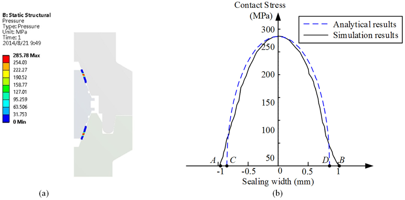
Contact stress of seal spherical surface in the operating mode: (a) distribution of contact stress and (b) contact stress comparison of analytical and simulation results.
Sealing contact characteristics with 1.5 times of the rated pressure
Relationship between the preload and the contact stress with 1. 5 times of the rated pressure
To ensure the sealing reliability, based on ISO 21329,
20
the seal structure must be able to seal 1.5 times of the rated internal pressure, 51.75 MPa. The corresponding parameters are p =51.75 MPa,
In the simulation, set the preloading pressure varying from 25 to 32 MPa with step of 0.06 MPa and the maximum contact stress is shown in Figure 15. At point P3, preloading pressure is 27.60 MPa and the maximum contact stress is 428.57 MPa, which is a little higher than 428.29 MPa and fits the sealing requirements. The corresponding axial preload is 1298.6 kN. The difference is 0.30% comparing with the analytical result.

The maximum contact stress versus axial preloading pressure with the 1.5 times of the rated internal pressure.
Simulation of sealing contact characteristics with 1. 5 times of the rated internal pressure
When the preloading pressure is 27.60 MPa, the deformations with internal pressure of 0 MPa and 1.5 times of the rated internal pressure in x-axis are shown in Figure 16(a) and (b). The maximum deformations in the cross section MM are −0.10402 and −0.064685 mm. The maximum difference of the deformation is in the central area of the gasket, as shown in Figure 16(c), and it increases 0.0573199 mm when internal pressure increases from 0 to 51.75 MPa. The deformations on y-axis are shown in Figure 17. The maximum deformations with internal pressures of 0 and 51.75 MPa are −0.35162 and −0.3096 mm, respectively. The biggest deformation increases 0.04202 mm along the positive direction of y-axis with the increase of the internal pressure from 0 to 51.75 MPa.

Deformation on x-axis: (a) internal pressure is 0 MPa, (b) internal pressure is 51.75 MPa, and (c) deformation comparison on cross section MM.

Deformation on y-axis: (a) internal press is 0 MPa, (b) internal pressure is 51.75 MPa, and (c) deformation comparison on cross sections NupNup and NdownNdown.
As shown in Figure 18(a), the distribution of the contact stress with 1.5 times of the rated internal pressure is similar to that in the operating mode. The maximum contact stress is 428.57 MPa, a little higher than 428.50 MPa, and fits the sealing requirements. Figure 18(b) shows that the sealing width of analytical result is CD = 2.5582 mm, and that of simulation result is AB = 3.3261 mm, which is 30.0% bigger than analytical result. This error is because of the assumption in the analytical method, as mentioned previously.

Contact stress of seal spherical surface with 1.5 times of the rated internal pressure: (a) distribution of contact stress and (b) contact stress comparison of analytical and simulation results.
Experiment and analysis
In order to validate the sealing performance of the collet connector and investigate the effect of the preload, an equivalent sealing experiment system was designed. The contact stress of the seal spherical surface cannot be measured directly; thus, the sealing width and the preload were used to measure the sealing performance. The experiment results have been compared with the analytical results to validate on the design of sealing contact mechanics.
Experiment system
The experiment system is shown in Figure 19, which is composed of a 200 tons (2000 kN) compression-testing machine, a top hub, a bottom hub, a seal gasket, and a hydraulic pump. The material of the seal gasket is stainless steel 316, and the roughness of the seal spherical surface is 0.4 µm. The hubs are blind-hubs with one side open. The hydraulic pump pressure is 0–80 MPa. In the experiment, it pumps water into the experimental connector and the pressure gauge indicates the actual pressure in the experimental connector.

Experiment system of the collet connector: (a) structure diagram of the experimental connector and (b) photo of the experiment system.
Sealing experiment in the preloading mode
In the preloading mode, the compression-testing machine applies a force upon the hubs until a given load. Then unload and measure the sealing width on the seal spherical surface with a vernier caliper. Indentations on the seal spherical surface before and after the experiment are shown in Figure 20, and the experimental, analytical, and simulation results are shown in Figure 21. It can be noted that the experimental results are a little smaller than the analytical and simulation ones, particularly when the preload is low. When the preload is 10 kN, the deformations are very small, even the analytical sealing width is only 0.54 mm. Meanwhile, the deformation on the edge is too small to be observed, which leads to an inaccurate measurement. The lower the preload is, the bigger the difference will be. Thus, the main cause of the differences is that the deformations are inconspicuous, and the measurement error is also a reason. The simulation results are greater than the analytical ones because of assumptions in the analytic method, and the difference between them has been discussed as mentioned above. In Figure 21, it can also be seen that when preload is 65 kN, which reaches the minimum preload required, analyzed in section “Sealing contact characteristics in the preloading mode,” the difference between the experimental sealing width (1.34 mm) and the analytical result (1.38 mm) is 2.90%, which meets the simulation result too.

Comparison of the indentations of the seal spherical surface before and after the experiment.

Comparison of sealing width of the experimental, analytical, and simulation results.
Sealing experiment with the internal pressure
To test the relationship between the preload and the maximum packing pressure, the compression-testing machine applies a force upon the hubs and the hydraulic pump supplies water into the interior of the hubs until the pressure does not increase, maintain the pressure for 1 h, and record the pressure value. Then this pressure is the maximum packing pressure with the given preload. Increase the force and repeat the above processes until the internal pressure is 1.5 times of the rated internal pressure (51.75MPa). The experimental results are listed in Table 1. When preload is 820 kN, the maximum packing pressure is 34.5 MPa; when preload is 1215 kN, the maximum packing pressure is 52 MPa, which is a little higher than 51.75 MPa. Meanwhile, in the range of the preload, the maximum packing pressure increases with increasing the preload, which indicates that increasing the preload appropriately is helpful to improve the sealing performance of the connector.
Results of sealing experiment with the internal pressure.

This experiment uses the leakage of the sealing structure as the criterion, while the analytical calculation and simulation use no leakage as the criterion; thus, the preload in this experiment is lower than that of the analytical calculation and simulation. As shown in Table 2, when the internal pressure is 34.5 MPa, comparing with the analytical results, the difference of the preload is 2.68% and the difference of sealing width is 4.09%; when the internal pressure is 51.75 MPa, the difference of the preload is 6.20% and the difference of sealing width is 4.69%. The simulation results are also the biggest ones and the difference between the analytical and simulation results has been discussed as mentioned above, which meets the experimental results well.
Comparison of the experimental, analytical, and simulation results with the internal pressure.
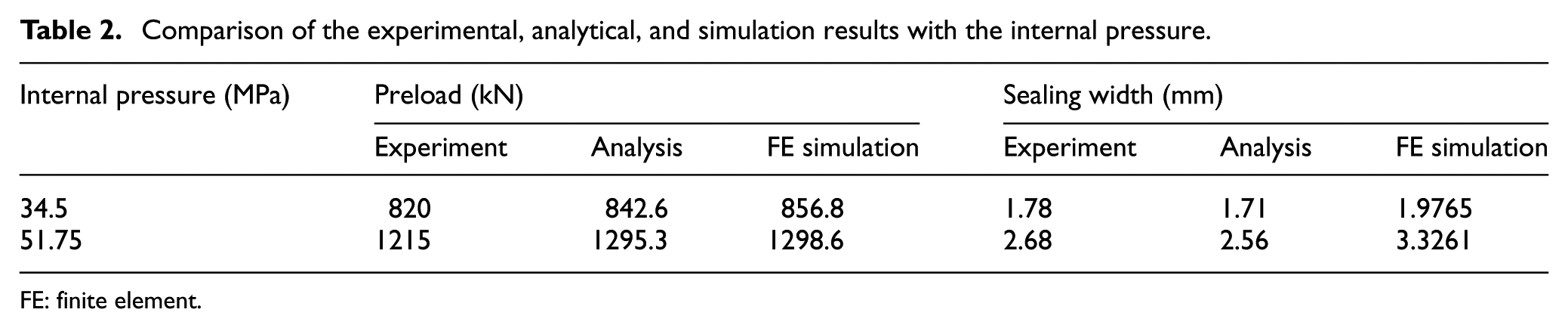
FE: finite element.
Conclusion
This article proposes an analytical calculation method for the contact stress of the lens seal gasket, which has guiding significance in subsea collet connector design. The analytical calculation, FE simulation method, and experiment design of contact stress proposed in this article not only applies to the 6.625 in subsea collet connectors and seal gaskets, but also contact characteristics of other seals with spherical surface and conical surface in ocean oil and gas industry. The specific conclusions are as follows:
According to Hertz contact theory, the contact between the seal gasket and hubs is equivalent to the contact of cylinders, and the contact stress mathematical model is established and then the parameters of contact, including sealing width, mean contact, stress, and maximum contact stress can be calculated.
Based on the mechanical analysis of the collet connector under various operating conditions, mechanical models of the seal structure in the preloading and operating modes are established to analyze the relationship between contact characteristics and preload. Then, calculation formulas of minimum preload of the seal gasket in the preloading and operating modes are deduced for the sealing mechanism of the metal seal.
3 To simulate the clamping effect of collets, 2D axisymmetric FE model is created with the axial preload applied on the end of the top hub. The sealing contact characteristics in the preloading and operating modes are simulated and compared with the analytical results. In the preloading mode, the difference between the analytical and simulation results of the axial preload is only 4.23%, and that of the sealing width is 21.8%; in the operating mode, the difference between the analytical and simulation results of the axial preload is only 1.69%, and that of the sealing width is 15.9%; in the mode with 1.5 times of the rated pressure, the difference between the analytical and simulation results of the axial preload is only 0.30%, and that of the sealing width is 30%. This error is because of the assumptions in the analytic method and tends to make the design a little bit safe. The differences of the simulation and the analytical results are acceptable.
An equivalent sealing experiment has been designed to test the sealing performance of the collet connector and investigate the effect of the preload. In the preloading mode, the experimental result of the sealing width (1.34 mm) is lower than the analytical result (1.38 mm), and the difference is 2.90%. In the experiment with internal pressure, when the internal pressure is 34.5 MPa, comparing with the analytical results, the difference of the preload is 2.68% and the difference of sealing width is 4.09%; when the internal pressure is 34.5 MPa, the difference of the preload is 6.20% and the difference of sealing width is 4.69%.
The analytical, the simulation, and experimental results of the sealing contact characteristics agree with each other very well. The accuracy of the analytical results is good enough to obtain the contact force, the sealing width, and the axial preload in the engineering application. Analytic equations obtained in this article can be used in the future engineering design and the simulation is not needed anymore.
Footnotes
Appendix 1
where X = x/a and X′ = x′/a, and
Acknowledgements
The authors also would like to express their gratitude to all the friends in our scientific team, who have always been helping and supporting us without a word of complaint.
Academic Editor: Yangmin Li
Declaration of conflicting interests
The author(s) declared no potential conflicts of interest with respect to the research, authorship, and/or publication of this article.
Funding
The author(s) disclosed receipt of the following financial support for the research, authorship, and/or publication of this article: This work was supported by a grant from the National Natural Science Foundation of China (grant no. 51279042) and the Royal Society International Exchange (grant no. IE141319).