
Abstract
To achieve automatic rolling of an unmanned vibratory roller, the path following control model of the vibratory roller was built and the influence of drum vibration is considered since the roller always works in the vibration condition. The vibration dynamic model was first established. The dynamic model of the vibratory roller under the influence of exciting force was then developed. The heading following control algorithm based on preview strategy was designed to control the path following errors in unmanned automatic rolling. The control performance of the algorithm was analyzed by simulation based on the vibration dynamic model and the dynamic and kinematic models of the vibratory roller. The control performance was also verified by the field automatic rolling experiments. Experimental results show that the maximum absolute lateral error of line path following is 24.5 cm in vibration rolling and 19.5 cm in non-vibration rolling at the traveling speed of 0.83 m/s. The average absolute lateral errors in vibration and non-vibration rolling are both less than 10 cm. The experimental results verify the effectiveness and achievability of the control algorithm for unmanned vibration rolling. Besides, the ratio of completely compacted area to the whole set area is 97.28% in the field automatic rolling experiment, which meets the requirements for practical use.
Keywords
Introduction
As a high-efficient compaction machinery, vibratory roller is widely used for constructing dams, airports, and roads. However, its excitation mechanism will produce severe vibration and it will cause physical discomfort if the operator stays in the state of vibration for a long time. In order to reduce the work intensity of the roller operator and to ensure the compaction quality, the researches on intelligent compaction technology and dynamic characteristics of vibration compaction have gained much attention.
Volvo, Bomag, Caterpillar, Sakai, and Chang’an University have developed real-time roller measurement systems to perform real-time compaction quality control. Intelligent road rollers of Bomag and Sakai can automatically adjust vibration amplitude according to compaction conditions and temperature changes by combining the position information received from the Global Positioning System (GPS) signal transmitting module installed on the roller and the corresponding compaction quality information.1,2 In order to provide roller measurements useful for engineering analysis and design, Kenneally et al. 3 built a vibratory drum–soil interaction model using dynamic finite element analysis and explored the relationship between vibratory roller response and system parameters such as elastic moduli and layer thickness. Li et al. 4 proposed a novel vibratory roller test bed to test vibratory property of the roller. Le et al. 5 and Gong 6 established the vibration dynamic model and evaluated the riding comfort of a vibratory roller under different soil grounds.
Although the above researches to a certain extent can be helpful to reducing operator’s fatigue and discomfort, the effects of vibration on the operator cannot be avoided. Unmanned vibratory roller is an alternative solution to the above problem. Besides, unmanned vibratory roller is also highly expected for operation cost reduction and improvement of work efficiency but the researches about it are much less than those of intelligent compaction. Chen 7 introduced an unmanned vibratory roller which could be remotely controlled to reverse the travel direction and to realize the steering control, while its traveling and steering speed could also be adjusted. However, the vibratory roller cannot achieve unmanned automatic rolling on set compacted area. To achieve unmanned automatic rolling, the path following control model of a vibratory roller needs to be studied. Vibratory roller is an articulated steering type vehicle which has two frames articulated by an active joint. The structural features and the extra degrees of freedom caused by joint weaken the lateral stiffness of the vehicle, resulting in a poor performance during the line path following and increasing the control difficulty.8,9 There are studies on the control of an articulated steering vehicle. Jujnovich and Cebon 10 designed a combined control model of a tractor and trailer by developing different control strategies at low and high speed to achieve accurate path following. Kim et al. 11 established a nonlinear lateral dynamic model of an articulated AWS (all-wheel-steering) vehicle and designed a decoupling compensator and a feedback controller for each decoupled loop to achieve automatic guidance control of the vehicle. However, the articulated steering of a vibratory roller is achieved by two hydraulic cylinders, which is different from the above-mentioned vehicles that steer the wheels to achieve turning, so the above-mentioned dynamic model and control strategy cannot be applied to the vibratory roller directly.
There have been some achievements in unmanned automation driving for LHD (load–haul–dump) vehicle whose steering structure is similar to that of a vibratory roller.12,13 Sasiadek and Lu 14 developed a fuzzy logic control system to keep a LHD vehicle along the planned path and running at the required speed. Nayl et al.15–17 developed a switching control scheme based on multiple model predictive controller to improve the performance of a LHD vehicle’s path following while compensating the varying slippage effect. The slip angle is considered in the control scheme. 18 In addition, Shiroma and Ishikawa 19 formulated nonlinear state equations of a wheel loader and a nonlinear state feedback controller was designed to make the vehicle follow a line path. Alshaer et al. 20 took into account the dynamics of a wheel loader and the construction working site constraints and developed PID (proportional–integral–derivative) controller to keep vehicle lateral error within 50 cm while traveling with constant speed. Delrobaei and McIsaac 21 proposed a closed-loop parking control system for an articulated steering mobile robot based on Lyapunov stability theory, and the effectiveness of the method in the presence of measurement noise was proved by simulation. The above path following control algorithms for LHD and similar vehicles have taken into account nonlinear characteristics, slip angle of the vehicle, and the influence of measurement noise. However, the influence of drum vibration should be considered in analyzing the performance of vibratory roller path following control method.
In this article, a reformed prototype of unmanned vibratory roller is first proposed in section “Working principle of unmanned vibratory roller.” As the GPS positioning antennas are installed on the front frame of the roller, the vibration dynamic model is established to study the response of the front frame under the vibration exciting force, which is discussed in section “Vibration dynamic model.” The vibratory roller’s kinematic model as well as the dynamic model under the influence of exciting force is then developed. The dynamic change of the traveling speed and heading angle of the roller can be obtained. Thus, the position and orientation of the roller are measured to calculate the path following errors, which is discussed in section “Model of the vibratory roller.” In order to control the path following errors in unmanned automatic rolling, the heading following control algorithm based on preview strategy is developed in section “Path following control algorithm.” The control performance of the algorithm is analyzed by simulation based on the vibration dynamic model and the dynamic and kinematic models of the vibratory roller in section “Simulation.” Finally, field automatic vibration and non-vibration rolling experiments of the reformed unmanned vibratory roller are then performed. The control performance of the algorithm under the influence of drum vibration is verified by the experimental results in section “Experiment and result.”
Working principle of unmanned vibratory roller
The reformed prototype of the unmanned vibratory roller is a YZ26E single-drum vibratory roller, as shown in Figure 1. The vibratory roller is an articulate vehicle whose two frames are articulated by an active revolute joint and the steering action is actuated by two hydraulic cylinders. In order to realize automatic unmanned rolling operation, the original hydraulic traveling and steering systems have been modified. In the original hydraulic traveling system, the traveling speed and direction of the roller are controlled by a manual handle which is used to adjust the displacement and fluid flowing direction of the servo pump, while a proportional electric valve is used for controlling in the reformed system. Furthermore, the original steering action is controlled by a steering wheel connected with a hydraulic steering gear, while a proportional speed control valve and an electric direction control valve are used in the reformed steering system. The vibration of the unmanned vibratory roller is achieved by controlling the electric valve of the hydraulic vibration system and the vibration mode can be adjusted.

YZ26E single-drum vibratory road roller.
Vibration dynamic model
Development of vibration dynamic model
The vibration exciting force is created by bi-directional rotating of the eccentric mass located at an effective moment arm in the vibrating drum. The vibrating drum is part of the front frame of the roller. To build the vibration dynamic model, it is assumed that the drum behaves as a rigid mass of md with the horizontal and vertical degrees of freedom. Besides, to simplify the analysis, it is assumed that the drum–soil stiffness and damping in the horizontal and vertical directions remain unchanged during compaction and the vibrating drum is always actively contacted with the ground and bounce or skid does not occur during compaction.
Based on the above assumptions, the 2-degree-of-freedom vibration dynamic model is established, as shown in Figure 2.

The vibration dynamic model.
In Figure 2, mf is the mass of the front frame (removing vibrating drum), F0 is the amplitude of vibration exciting force, and ω is the angular frequency of the exciting force. Meanwhile, kz-df, cz-df, kz-ds, and cz-ds represent the drum–frame and drum–soil stiffness or damping in the vertical direction, while kh-df, ch-df, kh-ds, and ch-ds are those in the horizontal direction. The rotating angle of drum is represented by α.
According to the vibration dynamic model shown in Figure 2, the vibration can be divided into two independent oscillations in the horizontal and vertical directions. The vibration dynamic equations have been established as expressed by

In the above equations, me is the eccentric mass and re is the effective moment arm. The vertical and horizontal displacements of the front frame are represented by zf and hf, while zd and hd are those of the drum. The displacement responses of the front frame to the vibration exciting force are considered as the measurement disturbances in the control model. The response of the drum rotating angle to the exciting force is considered as a disturbance in drum rotation, which can be obtained by the response of the horizontal drum displacement hd. I represents the moment of inertia of the drum about the drum center and r is the radius of the drum.
Analysis of vibration dynamic model
According to equation (1), the displacement responses of the front frame and drum to the exciting force F0 in the horizontal and vertical directions can be calculated independently. The dynamic displacement responses of the front frame and drum in each direction can be calculated using numerical integration. The initial displacements and velocities of the front frame and drum are set as zero in the numerical integration. In order to evaluate the influences of the vibration, the responses of the front frame and drum in both directions are analyzed. The parameters of the roller are obtained referring to the manual of the YZ26E roller, while those of the vibration system are obtained according to the work by Gong, 6 where Gong evaluated the vibration parameters of a same type vibratory roller under different soil grounds. The parameters of the vibratory roller and the vibration system are as follows: md and mf (unit: kg); F0 (unit: N); ω (unit: rad/s); kz-df, kz-ds, kh-df, and kh-ds (unit: N/m); cz-df, cz-ds, ch-df, and ch-ds (unit: kg/s); I (unit: kg m 2 ); and r (unit: m) are shown in Table 1.
The parameters of the vibratory roller and the vibration system.

According to equation (1) and the above parameters, the vertical and horizontal displacement responses of the front frame and drum are derived as shown in Figures 3 and 4. As the figures show, the displacement responses of two parts both have large fluctuations when the vibration starts. However, the responses of the front frame decay over time, while those of the drum finally reach to steady responses with periodic change of the amplitude. The maximum amplitudes of the horizontal and vertical responses of the front frame are 0.9 and 1.3 cm, respectively, while those of the drum are 1.1 and 1.4 cm. The maximum amplitudes of the steady responses of the drum are both less than 0.5 cm.
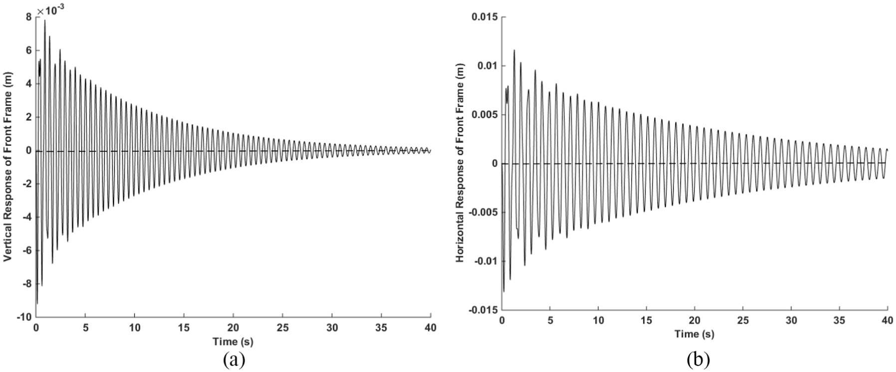
The displacement responses of front frame: (a) vertical response and (b) horizontal response.

The displacement responses of drum: (a) vertical response and (b) horizontal response.
As the parameters of the roller are stable in the compaction process and it is assumed that the drum–soil stiffness and damping in the horizontal and vertical directions remain unchanged during compaction, the main parameters that affect the responses of the front frame and drum are cz-df, kz-df, ch-df, and kh-df. Considering the presence of uncertainties in system parameters, one of these parameters is assumed to change to analyze the influence of it on the displacement responses of the front frame and drum. Figures 5–8 show different vertical and horizontal responses of the front frame and drum with different parameters.

The vertical displacement responses with different kz-df of (a) front frame and (b) drum.

The vertical displacement responses with different cz-df of (a) front frame and (b) drum.

The horizontal displacement responses with different kh-df of (a) front frame and (b) drum.

The horizontal displacement responses with different ch-df of (a) front frame and (b) drum.
As the figures show, the damping coefficients have little effects on the displacement responses when the vibration starts. A higher damping coefficient just causes slight decreases in the amplitudes of the responses. Compared with the damping coefficients, those of stiffness have more effects on the displacement responses. A higher stiffness coefficient will cause larger displacement responses of the front frame and drum at the beginning. However, it will also lead to stronger attenuation effects on the responses of the front frame. Although the maximum amplitudes of the responses are larger with a higher stiffness, the variations of them are relatively small. Besides, a higher stiffness will lead to a relatively higher response frequency.
Model of the vibratory roller
Roller’s kinematic model as well as the dynamic model under the influence of exciting force is developed to obtain the dynamic change of the traveling speed and heading angle of the roller. Therefore, the position and orientation of the roller in the road coordinate can be acquired. A single-drum vibratory roller in the road coordinate and the geometry of the roller are shown in Figure 9.

The geometry of a single-drum vibratory roller.
As can be seen, two frames (front and rear) of the roller are articulated by a revolute joint. Therefore, the position and heading of the vibratory roller is indicated by the vector pT = [x1, y1, θ1, x2, y2, θ2]. (x1, y1) represents the coordinates of the center of the front frame and (x2, y2) represents the coordinates of the center of the rear frame. θ1 and θ2 are the headings of the front and rear frame correspondingly. Since two parts of the roller are connected by the joint, the position and heading of the rear frame can be obtained by those of the front frame as well as the steering angle

The distance between the joint and the center of the front frame is the same to that between the joint and the rear frame, so l is used to indicate the distance between the joint and the center of two parts in the above equations. By assuming that the kinematic and dynamic properties of the vibratory roller are symmetrical with respect to its components longitudinal axes, that the contact between tires and surface of motion is point-wise and that the motion is planar and slippage-free, the kinematic model of the vibratory roller is obtained as follows

In the above equations, v is the velocity of the center of the front frame and Ω is the heading angular velocity of the front frame. By applying Kane equations, the dynamic model of the vibratory roller which consists of two parts and is submitted to holonomic and non-holonomic constraints is described as follows
N(q) is the inertia matrix of the vibratory roller and F(q,β) is a vector describing Coriolis and centripetal forces. Besides, J is the transform matrix relating generalized velocities to workspace velocities. Generalized velocities are indicated by the vector βT = [v, Ω]. M is the extended mass matrix of the roller that is a diagonal matrix and W is the extended angular velocity matrix which is also a diagonal matrix. The vector w represents the active forces and moments applied to the system.
Combining equations (2) and (3), the transform matrix J relating generalized velocities to workspace velocities is obtained

According to equation (4), the inertia matrix N(q) is derived

In the above equations, m1, j1, m2, and j2 represent the mass or the moments of inertia about the joint of the front and rear parts of the roller correspondingly.
According to equation (4), the force vector F(q,β) is derived
The active forces and moments applied to the system are indicated by the vector wT = [−fzx, 0, fs − fzy, fp, 0, −fs + fzy], where fzx represents the longitudinal horizontal vibration force applied on the drum and fzy represents the change of frictional moment applied on the joint caused by the vertical vibration force on the drum. The propulsion force represented by fp and fs represents the steering moment on the joint. The horizontal and vertical vibration force is obtained from equation (1) and the change of frictional moment is obtained according to the work by Yin. 22 The expressions of fzx and fzy are shown as follows

In equation (8), μf represents the friction coefficient between drum and ground and W is the width of the drum. Therefore, the dynamic model under the influence of exciting force is finally derived as follows

H is a transform matrix which is expressed as follows

According to equation (9), the dynamic change of the velocity and heading angular velocity of the roller is obtained from the dynamic model. Based on the updated velocity and heading angular velocity, the updated position and orientation of the roller in the road coordinate can be acquired by the kinematic model derived from equation (3).
Path following control algorithm
In the actual rolling operation, unmanned vibratory roller mainly travels along straight lines to complete the rolling of the set area. The vibratory roller works on uncompacted and uneven roads, thus causing errors between the actual path and the desired path. It is necessary to design the straight path following algorithm to control the path following errors. The straight path following errors of the vibratory roller are determined by lateral error el, heading error eθ, and angle error eϕ, which are defined as follows

The actual coordinates of the center of the front frame are represented by (x, y) and θ is the actual heading of it. The desired coordinates of the center of the front frame on the set line path are represented by (xd, yd) and θd is the desired heading. The definition of errors is shown in Figure 10.

The line path following of a single-drum road roller.
In order to achieve accurate line path following for unmanned vibratory roller, the path following controller is designed to make lateral error el, heading error eθ, and angle error eϕ converge to zero as time increases. Preview control in which the driver anticipates the path ahead and makes an appropriate steering action based on knowledge of the vehicle dynamics to compensate for errors and disturbances is commonly used in vehicle path following control. 23 According to the preview control, the heading following control based on preview strategy is applied to achieve line path following of the vibratory roller. The desired heading is calculated based on the lateral error and the preview distance L at the corresponding speed, 24 as shown in Figure 10. The controller then adjusts the steering angle according to the desired heading and the actual heading of the front frame measured by the orientation system. The incremental adjustment angle Δϕ exported by the controller is shown as follows

In the above equation, k1 and k2 are the steering angle adjustment factors. In real straight line path following control, the lateral error el, heading error eθ, and angle error eϕ are assumed to be small. Therefore, the linear equation for line path following error is derived by combining equation (12) and the linearized equation (11), which is shown as follows

The steering angle adjustment factors k1 and k2 are determined according to Lyapunov stability theory, which makes lateral error el, heading error eθ, and angle error eϕ finally converge to zero. PID algorithm is applied to control the angular speed and an angle encoder is implemented to measure the steering angle and the angular speed to achieve closed-loop feedback control of the steering angle. The traveling speed of the vibratory roller should maintain at the desired value in the rolling operation. Therefore, PID algorithm is also applied to control the traveling speed of the unmanned vibratory roller. The closed-loop control of the traveling speed is achieved by the real-time speed feedback through the GPS speed sensor mounted on the front frame.
Simulation
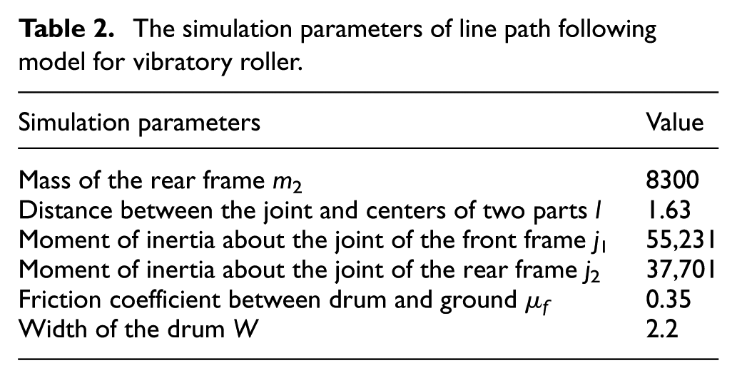
In order to verify the performance of the path following control of unmanned vibratory roller, the control model is built in the Simulink, as shown in Figure 11. The simulation parameters of the model are obtained from Tables 1 and 2. The parameters m2 (unit: kg), l (unit: m), j1 and j2 (unit: kg m 2 ), W (unit: m) are obtained referring to the manual of the YZ26E roller and μf are obtained according to the work by Yin. 22

The path following control model in simulation.
The simulation parameters of line path following model for vibratory roller.
As shown in Figure 11, the path following errors are determined by the output position, heading, and angle of the kinematic model of the roller. The input of the traveling speed controller is the error between the output speed and the desired speed, while the input of the angular speed controller is the error between the measured angular speed and the desired angular speed. The output of the controller is the change rate of traveling speed and heading angular speed, thus the propulsion force and the steering moment are obtained. The updated speed and heading angular speed are achieved by the dynamic model under the influence of exciting force. The horizontal displacement response of the front frame to the vibration exciting force is considered as the position measurement disturbance, and the response of the drum rotating angle is considered in calculating the disturbance of the traveling speed combined with the drum radius.
In the simulation model, as the actual range of the steering angle is between ±35° and the maximum angular speed of the roller is 11°/s, those two variables are set within the permissible range to meet the actual situation. The initial values of lateral error, heading error, and angle error are set to be 2 m, 6°, and −3° in the simulation to verify the control effects of the line path following algorithm on those errors. In order to study the influence of drum vibration on the control precision of unmanned automatic rolling, simulations have been made with and without the influence of exciting force in the model. Figure 12(a)–(c) correspondingly shows the simulation results of lateral error, heading error, and angle error of the line path following for vibratory roller with initial errors. X-axis represents simulation time (unit: s) which is set as 40 s. Y-axis in each figure correspondingly represents lateral error (unit: cm), heading error (unit: °), and angle error (unit: °).

The errors of vibration rolling and non-vibration rolling in simulation: (a) lateral error, (b) heading error, and (c) angle error.
As the simulation results show, lateral error, heading error, and angle error converge to zero with increase in time, and after 25 s, the errors are close and approaching to zero even though there are initial errors, which proves the control stability of the algorithm. In addition, the fluctuation amplitude of each error in vibration condition is larger than that in non-vibration condition. Meanwhile, there is a time delay in each error of vibration condition comparing with the error of non-vibration condition in the start stage. Consequently, the control precision of unmanned automatic rolling is worse in vibration condition than that in non-vibration condition, but due to the control stability and effectiveness of the heading following control algorithm based on preview strategy, the path following errors converge to zero and the unmanned vibratory roller can achieve the following of the set line path in both vibration and non-vibration conditions.
Different simulations are made under different parameters of the vibration system to test the influences of parameter uncertainties on the results of the simulation model. The results show that the variations of the parameters have no significant impact on the model. As the simulation results under different parameters are almost the same, the simulation curves are not displayed here. According to the analysis of section “Analysis of vibration dynamic model,” the impacts of the parameters are mainly caused by the stiffness coefficients. However, as the variations of the responses of the front frame and drum caused by different stiffness coefficients are limited and the displacement responses of the front frame decay over time, the model is not sensitive to the parameter uncertainties of the vibration system.
Experiment and result
Experiment setup
In order to analyze the actual control precision of unmanned automatic rolling and to verify the control performance of the line path following algorithm in real vibration and non-vibration rolling, field automatic vibration and non-vibration rolling experiments of the reformed unmanned vibratory roller are performed, as shown in Figure 13. The road coordinates of the antenna on the left side of the roller (looking along the forward direction) are measured by the SPS855 GPS module mounted on the roller. High-precision real-time kinematic (RTK) positioning data can be obtained by combining the satellite signal received from the positioning antenna and the base station signal received from the internal radio. The GPS equipment are set up by the Trimble TSC3 controller and the site coordinate system is imported to the SPS855 module. GPS quality can be indicated by the output NMEA protocol. When the RTK signal is fixed, real-time dynamic positioning precision in the horizontal direction of SPS855 can reach to 8 mm. In the experiments, we only care about the position of the roller on the rolling plane, and therefore, the vertical precision is not considered in the measurement. As the experiments are performed on a wide open site and a 35W TDL450Hx transmitting radio is used, the interference in the satellite and RTK signals is reduced. In addition, the SPS855 module has high computational and filtering performances, and therefore, the stability of the measurement precision is ensured. If the signals are interfered and RTK signal is float or lost, the roller will stop and wait until the signal is fixed again. According to the analysis of section “Analysis of vibration dynamic model,” the maximum amplitude of the horizontal displacement response of the front frame is 1.3 cm when the vibration starts and it decays over time. The amplitude of the response is less than 1 cm after 5 s, so the positioning accuracy can reach to centimeter level and the influence of the displacement response of the front frame on the measurement accuracy is acceptable.

The experiment of automatic rolling for unmanned vibratory roller.
The inclination sensor is used to compensate the measuring error caused by the roll and pitch angle of the front frame. The installation of the inclination sensor is shown in Figure 14(a). The coordinates of the center of the front frame are then derived from the processed position data through coordinate transformation. By combining the data from two antennas, the real-time heading of the front frame is obtained by the SPS555 heading module mounted on the roller. The measurement precision of SPS555 can reach to 0.09° when RTK signal is fixed. The real-time steering angle of the roller is measured by a 16-bit angle encoder mounted on the joint, as shown in Figure 14(b). The measurement resolution of the encoder is set as 0.1° in the experiments. The real-time lateral error, heading error, and angle error are then calculated by equation (11).

The installation of the sensors: (a) inclination sensor and (b) angle encoder.
Results and discussions
The initial values of lateral error, heading error, and angle error in the experiments are set to be the same as in the simulation model to verify the control effects of the line path following algorithm. And field automatic vibration and non-vibration rolling experiments of the unmanned vibratory roller are performed with and without the influence of exciting force. Figure 15(a)–(c) correspondingly shows the experimental results of lateral error, heading error, and angle error of the line path following for unmanned vibratory roller with the same initial errors.

The errors of vibration rolling and non-vibration rolling in experiment: (a) lateral error, (b) heading error, and (c) angle error.
As the experimental results show, lateral error, heading error, and angle error of the experiments converge to zero with increase in time, and after 30 s, the errors are close and approaching to zero even though there are initial errors. Therefore, control stability of the algorithm is proved both by the simulation and the experiments. The fluctuation amplitude of the experimental errors in vibration condition is larger than those in non-vibration condition, which is the same as is in the simulation model. However, the response time of each error in the experiments is longer than that in the simulation both in vibration and non-vibration conditions, as shown in Table 3. The time delay partly contributes to the response latency of the hydraulic steering system which is not taken into consideration in the simulation. Moreover, the time delay of each error in the vibration condition is more obvious than that in the non-vibration condition and the amplitude of the heading and angle errors in the experiment is larger than that in the simulation in the vibration condition. The increases in adjustment time and amplitude are primarily due to polarization compaction of the vibrating drum caused by the asymmetry of the drum during manufacturing and installing. Under the influence of polarization compaction, the vibratory roller is more susceptible to lateral slip, thus causing larger following errors and the control performance of the algorithm is weakened when the tuned adjustment factors are constant.
Comparison between the simulation and experimental results.

To make a further comparison on the control precision of line path following in vibration and non-vibration conditions, unmanned automatic vibration and non-vibration rolling experiments are performed on the same set line path. The traveling speed of the vibratory roller is set as 0.83 m/s. Figure 16(a)–(c) correspondingly shows the absolute lateral error, absolute heading error, and absolute angle error of vibration and non-vibration rolling on the same set line path. Table 4 displays the comparison between the absolute errors of line path following in two rolling conditions.

The absolute errors of vibration rolling and non-vibration rolling on the same set line path: (a) absolute lateral error, (b) absolute heading error, and (c) absolute angle error.
The comparison between the absolute errors of line path following in vibration and non-vibration rolling.
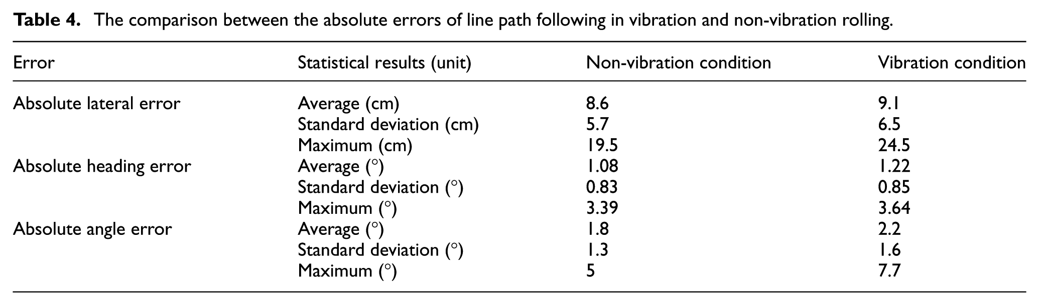
As shown in Table 4, the maximum absolute lateral error is 24.5 cm in vibration rolling and 19.5 cm in non-vibration rolling at the traveling speed of 0.83 m/s. The averages of the absolute lateral error in two conditions are both less than 10 cm. The difference between the maximum absolute heading errors in two conditions is 0.25°, while the difference between the maximum absolute angle errors is 2.7°. The averages of the absolute heading and angle error in vibration rolling have small differences from those in non-vibration rolling. The differences between the averages of these two absolute errors are both less than 1°, which verifies the stability and effectiveness of the control algorithm in vibration rolling.
In the actual rolling operation, the overlapping method is used to complete the rolling for the whole set area. Figure 11 shows the number of passes on the set area in unmanned automatic rolling, which can reflect the actual rolling quality of the unmanned vibratory roller. The set area is 70 m in length and 4 m in width. In manual rolling operation, as the width of YZ26E’s rolling drum is 2.2 m, the overlap rolling width is set as 20 cm not only to ensure the rolling quality but also to keep a high working efficiency. The number of non-vibration rolling is set as two, while the number of vibration rolling is set as eight depending on the nature of the compacted material of the set area. Therefore, the overlap width and the numbers of vibration and non-vibration rolling in unmanned automatic operation are set to be in accordance with those of the manual operation. The actual number of the paths is two on the set area. As shown in Figure 17, different colors represent different numbers of passes on the set area. The completely compacted area whose number of passes is 10 and more covers 97.28% of the set area, while the average rolling quality of manual operation is beyond 95% of the set area. Therefore, the unmanned vibratory roller meets the requirements for practical use. Compared with the manual rolling, the unmanned vibratory roller can maintain a high-level rolling completion, while that of a manual one will decrease with increase in time because of the fatigue and discomfort caused by the long-time operation. Besides, the unmanned vibratory roller can reduce the work intensity of the operator. However, as it is assumed that the drum–soil stiffness and damping remain unchanged during compaction, the influence of them is not discussed here. Besides, polarization compaction of the vibrating drum is not considered in the proposed model, so the model is not well suitable for the road with a high roughness. Future work will focus on the influence of polarization compaction on the path following performance of the unmanned vibratory roller and we will further study the control performances of the model on the road with different rolling materials.
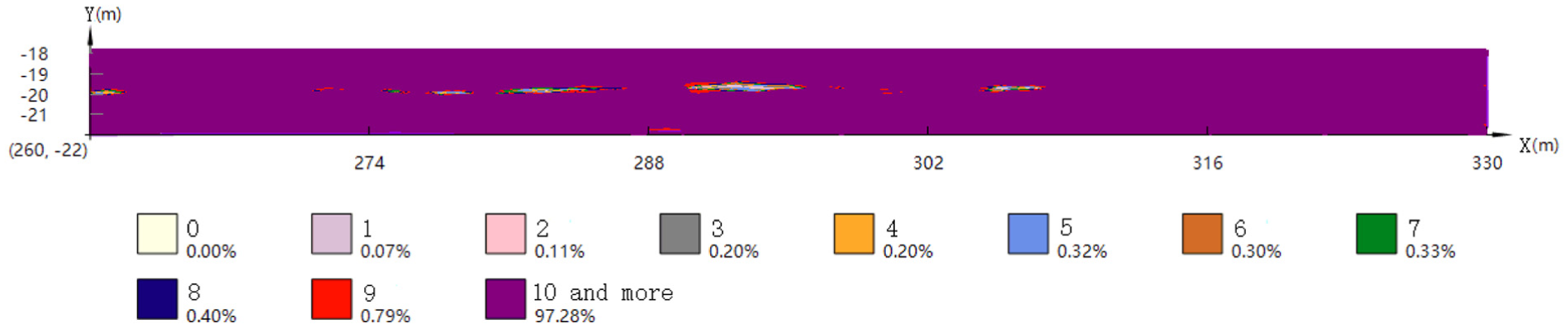
The report on the number of passes on the set area in unmanned automatic rolling.
Conclusion
In order to achieve automatic rolling of an unmanned vibratory roller in non-vibration and vibration conditions, the vibration dynamic model is first established. Then, the kinematic model as well as the dynamic model under the influence of exciting force is developed. The heading following control algorithm based on preview strategy is developed to control the path following error between the actual path and the desired path in vibration and non-vibration rolling operations. The control performance of the algorithm is verified both by the simulation and field automatic rolling experiments. The simulation and experimental results show that the unmanned vibratory roller can achieve the following of the set line path in both vibration and non-vibration conditions even though there are initial errors, which shows the control effectiveness and achievability of the algorithm in unmanned automatic rolling. Meanwhile, the report of unmanned automatic rolling shows that the unmanned vibratory roller meets the requirements for practical use.
Footnotes
Handling Editor: Rahmi Guclu
Declaration of conflicting interests
The author(s) declared no potential conflicts of interest with respect to the research, authorship, and/or publication of this article.
Funding
The author(s) disclosed receipt of the following financial support for the research, authorship, and/or publication of this article: The work is supported by the National Key R&D Plan of China (grant no. 2016YFC0802906), National Key R&D Program of China (grant no. 2016YFC0802900), and Fundamental Research Funds for the Central Universities of China.