
Abstract
This research proposes a hybrid model for predicting the vibration behavior of a single-stage spur gear transmission system under various misalignment conditions. The model combines finite element analysis (FEA) to estimate the forces transmitted by the gears to the shaft, with an analytical model to predict the acceleration spectra at the bearing base. The hybrid approach balances accuracy, computational efficiency, and development ease, making it suitable for design-stage analysis. The model evaluates the influence of combined misalignments (axial, radial, and yaw) on vibration levels, which is more realistic than individual misalignments. Results from the hybrid model show a strong correlation (0.98) with experimental data, with discrepancies not exceeding 15%. The study highlights that radial and angular misalignments significantly influence vibration spectra, while axial misalignment has minimal impact. The proposed model offers a computationally efficient alternative to fully dynamic simulations, providing valuable insights for gear system design and misalignment diagnosis.
Introduction
The dynamic behavior of mechanical systems, particularly gear transmission systems, is a critical area of research due to its significant impact on the performance, reliability, and longevity of machinery. 1 Gear systems are widely used in various industrial applications, including automotive, aerospace, and manufacturing, where precise power transmission is essential for optimal operation. However, due to manufacturing errors, assembly issues, or operational conditions, failures can occur in these systems, leading to transmission inefficiencies. 2 A typical failure caused by such factors is shaft misalignment. These misalignments—axial, radial, and angular—alter the contact forces between gears, resulting in changes in normal vibration patterns and increasing surface and bending stresses on the gear teeth.3,4 This increase in stresses can ultimately result in premature failure of the system. In this regard, vibration measurements can serve as input for models aimed at predicting this type of misalignment failure. Accurate modeling of gear systems under misalignment conditions is therefore crucial for predicting dynamic behavior and designing robust systems that can withstand operational challenges.
Studies related to the evaluation of dynamic parameters or the development of models through experimentation are limited due to the complexity and costs associated with manufacturing and developing a test bench capable of generating controlled shaft misalignments and measuring their effects on vibrations. Khan et al. 5 developed a test bench that allows for the generation of misalignments in the shafts of a single-stage power transmission system. In their work, they investigated the effects of individual misalignments—radial, axial, and angular (yaw and pitch)—on vibration and acoustic measurements to generate predictive models. Zou et al. 6 proposed an analytical model incorporating angular misalignments and tooth modifications. This model was experimentally validated using a test bench, showing good consistency in the results. In a previous study, 7 experimental tests were conducted to study the effect of combined misalignments (axial, radial, and angular) on vibration measurements taken from the bearings of a single-stage spur gear transmission system. This work allowed for the evaluation of both the individual effects of misalignments and the interactions between different types of misalignments.
Most studies focus on developing analytical models validated with finite element simulations and some experimental results. Hu et al. 8 developed a 6-degree-of-freedom dynamic model that considered specific ranges of shaft misalignments. They solved the model using a Chebyshev approximation, finding good agreement when compared to simulated values. Xie et al. 9 proposed a model that accounted for the dynamic fluctuations of the meshing force under angular misalignment conditions. The proposed model is a torsional dynamics model that demonstrated better results than traditional models, where the contact state change and mesh stiffness are static force-dependent, when compared to finite element results. Misalignment in gears can also be caused by shaft deflection. The effect of this deflection on the dynamic response of a single-stage gear transmission system was analyzed by Guo et al., 10 who proposed an analytical model validated by finite element analysis. Recently, Chen et al. 11 investigated the effect of misalignments in planetary systems, specifically in herringbone gears, using a dynamic model that considered different types of misalignments. Their model was validated through simulations and experimental results. Che et al. 12 developed a dynamic model that considered angular misalignment and variable backlash, finding that stiffness decreases under angular misalignments parallel to the contact plane.
The detection of misalignments in gear-driven power transmission systems through vibration analysis is currently neither a straightforward nor a fully standardized process. In many cases, it requires measurements in multiple directions, both radial and axial. In the work of Wang 13 it is shown that misalignment in shafts supporting gears generates spectra in which harmonics of the gear meshing frequency (GMF) predominate, along with an amplitude modulation waveform with a period of approximately two cycles per revolution. While certain demodulations and the predominant presence of specific harmonics of the GMF in the vibration spectrum could indicate misalignments, they might also be attributed to other types of faults in the system. Further research is needed to develop dynamic models that can predict, in a relatively simple manner, the dynamic behavior of gear systems subjected to misalignments. This work presents a hybrid model that predicts accelerations at the bearing base of a single-stage spur gear transmission system subjected to combined shaft misalignments. The model’s results are compared with experimental data. Combined misalignments are more realistic, as in practice, misalignments occur simultaneously rather than individually, which is how most studies have approached them.
Hybrid model
Marafona et al. 14 proposed a valuable classification system for evaluating dynamic models using four key parameters: accuracy, computation time, implementation procedure, and resources. Accuracy refers to the model’s ability to generate results that closely match real-world values. Computation time reflects the computational effort required to solve the model. The implementation procedure details the steps needed to solve the model, including the skills and knowledge required in areas like finite elements, mathematics, programming, or the specific phenomenon itself. Finally, resources refer to the computational power necessary to solve the model. Several types of models can be used to estimate the dynamic behavior of a mechanical system: analytical, finite element, hybrid, and approximate analytical models. The choice of model depends on several factors:
Computational resources: The computational power available to solve the model.
Expertise: The knowledge and skills required in areas like physical modeling, mathematics, finite elements, and simulation software.
Solution time: The criticality of obtaining results quickly.
Replicability: The ease of reproducing and sharing the model’s results.
Prioritizing accuracy: When accuracy is the primary concern, and computational resources, expertise, and solution time are not limiting factors, finite element models offer the most precise prediction of dynamic response.
Balancing accuracy and speed: Conversely, if time is a critical factor, and high accuracy is less important, approximate analytical models can be a valuable option.
Development ease: When selecting a new model, a fifth parameter can be considered: development ease. This refers to the time and effort required to create the model itself.
Table 1 presents a rating system (from 1 to 4) for the different types of models based on the five previously mentioned parameters. A rating of 4 indicates the best performance in that category, while 1 indicates the worst. A model with a rating of 4 in accuracy has the highest accuracy in predicting real-world behavior. A model with a rating of 4 in computation time requires the least computational resources to solve. A model with a rating of 4 in implementation procedure requires the fewest steps and least specialized knowledge to implement. A model with a rating of 4 in resources requires minimal computational power to solve. A model with a rating of 4 in ease of development is the easiest to create.
Selection of the type of dynamic model to develop.

As the primary goal is to understand the impact of combined misalignments on vibration during the design stage, this research prioritizes both model accuracy and ease of development. These factors were assigned the highest weighting (30% each) in Table 1. Computation time was considered next, receiving a 20% weighting. Finally, implementation procedure and resource requirements were each assigned a 10% weighting due to their relative importance in this context.
Based on this evaluation, a hybrid model emerges as the optimal choice. Hybrid models combine finite element analysis with analytical or approximate analytical methods. This approach proves valuable when developing a highly accurate analytical model is challenging. It provides a balance between precision, computational demands, and execution speed.
Vibrations in bearings arise from forces generated by the connected shaft. In a simple spur gear system, these forces depend on the interaction between engaged gears. A complete analytical model requires determining these forces. This calculation is relatively straightforward for perfectly aligned gears.
However, misalignments introduce complexities. Contact and tangential forces change due to altered contact areas. In an aligned case, the tangential force acts along a line with a magnitude equal to the gear face width. While the position of this line may vary across the tooth face, it remains constant in an absolute coordinate system. Consequently, the distance from the shaft center to the point of force application remains constant. This translates to relatively constant forces acting on a perfectly aligned gear pair, with minimal variations over time.
When combined misalignments are present, the line of meshing forces changes in size, inclination, and position. This not only alters the average force value but also introduces significant time variations in the force.
Given the challenges associated with analytically predicting forces resulting from misalignments, this research proposes utilizing finite element simulation. This simulation will provide the force data that will then be used as inputs for an analytical model capable of predicting bearing unit acceleration. Essentially, the finite element simulation acts as a pre-processing step to generate the necessary force data for the analytical model.
The finite element method is a well-established tool for analyzing stress and strain in power transmission systems. A good method for gear analysis using finite elements was proposed by Litvin and Fuentes. 15 Their approach involves discretizing (dividing into smaller elements) three teeth, including the gear rim. This three-tooth model is sufficient for studying stress and strain in gear pairs with a contact ratio (ratio of teeth in contact) less than two. A three-tooth mesh captures a complete mesh cycle, from the initial contact between teeth to the end of the mesh. Since most spur gears have a contact ratio below two (with higher ratios being less common), discretizing three teeth with their rims offers the most efficient solution for finite element modeling. Modeling the entire gear would incur unnecessary computational costs without significant benefit.
Litvin and Fuentes 15 proposed a method for dividing a gear tooth into six parts using six auxiliary intermediate surfaces. This segmentation allows for greater control over the discretization of the individual subvolumes within the tooth. To implement boundary conditions and loads, the authors suggest using rigid surfaces on the inner and side sections of the discretized teeth. These surfaces can be coupled to reference points, typically the gear centers aligned with the shaft positions. While Litvin and Fuentes presented an analytical procedure for gear surface generation and discretization, this research adopted a different approach. Here, the initial gear model was created using Solidworks® for computer-aided design (CAD) purposes. Subsequently, the model was transferred to Abaqus® software for mesh generation due to its well-regarded meshing capabilities.
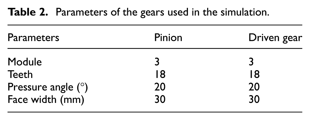
While first-order tetrahedral elements can be used for analyzing stress in 3D geometries, they tend to exhibit a stiff response to bending stresses. This can be mitigated by using higher-order elements, such as second-order tetrahedral elements. However, for better computational efficiency, first-order hexahedral elements offer a more suitable solution. These elements can achieve the same accuracy as second-order tetrahedral elements with a lower computational cost. 16 Therefore, the chosen element type in Abaqus is C3D8, which has eight nodes and 24 degrees of freedom. Figure 1 depicts the finite element model for the analyzed spur gear pair. Reference Point 1 (RP-1) represents the driven gear and it is coupled to its internal and lateral surfaces. A constant torque is applied at this point, while rotation about the z-axis is allowed. Reference Point 2 (RP-2) represents the pinion and it is coupled to its internal and lateral surfaces. A specific angular displacement is applied at this point about the z-axis. The gear parameters for the pinion and driven gear used in the simulation are identical to those employed in a previous experimental analysis 7 and they are detailed in Table 2.

Finite element model for the analyzed spur gear pair.
Parameters of the gears used in the simulation.
Two primary methods exist for contact discretization: node-to-surface and surface-to-surface. While the surface-to-surface method generally offers higher accuracy, the discrepancies between the two approaches become negligible with a refined mesh. Considering the lower computational cost of the node-to-surface method, it was chosen for this analysis.
If the transmission model incorporated the shafts and bearings, a transient dynamic analysis would be necessary to accurately predict system accelerations. However, the primary objective of this research is to determine the forces applied on the shafts due to gear interaction under both aligned and misaligned conditions. Therefore, a static analysis is employed. This approach significantly reduces computational costs and remains suitable for providing input data to the analytical model. This data will be used to estimate the trends in bearing unit acceleration behavior under various misalignment scenarios.
Frictionless and tangential contact properties were utilized for the analysis. A constant torque of 3.25 Nm was applied at reference point RP-1 as the reaction load. At reference point RP-2, an angular displacement of 0.71 radians was applied via a ramp function, ensuring a complete meshing cycle.
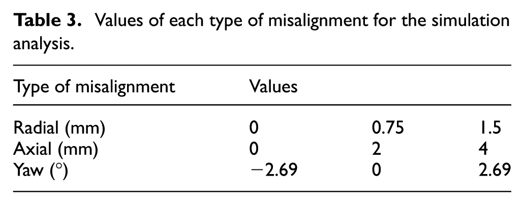
The finite element model was developed to analyze different misalignment conditions for the spur gear pair with the parameters defined in Table 2. Each experimental condition evaluated represents a combination of three misalignment types: axial, radial, and yaw (angular). Three levels were chosen for each misalignment type, resulting in a total of 27 simulations. The specific levels employed for each factor in the simulation analysis are detailed in Table 3.
Values of each type of misalignment for the simulation analysis.
The Abaqus® module assembly function was used to create the various misalignment combinations. Figure 2 illustrates some of the configurations implemented.

Pair of spur gears with 1.5 mm, 4 mm, and 2.69° of radial, axial, and yaw misalignment respectively (left) and 1.5 mm, 2 mm, and −2.69° of radial, axial, and yaw misalignment respectively (right). The upper gear is the pinion and the lower gear is the driven gear.
Due to the 20° pressure angle, the tangential force component acting at the gear contact point is greater than the radial component. Since the acceleration response heavily depends on this force, the tangential force was chosen for analysis to better observe significant changes in vibration behavior. Figure 3 displays the average tangential force transmitted to the pinion shaft (120 N) alongside a sample tangential force curve for a misaligned case. The x-axis in Figure 3 represents the time it takes for a complete meshing cycle at a shaft speed of 282 rpm. Tangential force data was extracted for all misalignment configurations. These force signals were then replicated to reach a total analysis time of 60 s. This extended duration ensures the stabilization of the response variable within the analytical model.

Tangential force (Fy) in the center of the pinion gear (RP-2) in a period of meshing for the aligned condition (black) and an angular misalignment condition with 2.69° (red).
As previously stated, the hybrid model incorporates a simulation component that is responsible for calculating the forces that are transmitted to the shaft that is supporting the pinion gear. The processed force signals serve as the inputs for the analytical model. The proposed model considers the shaft and the external loads that act on it. Figure 4 shows the shaft on which the force acts due to meshing at one end and the reaction torque at the other end. At the opposite end of the shaft, the motor, which is coupled to the system, applies a torque. Given that a cantilevered one-stage transmission system is being analyzed, it can be represented by an equivalent system of stiffness (k) and damping (c) in both the vertical and horizontal components, with the two bearings situated between the two ends of the shaft. In order to determine the velocity and acceleration of the system in the x direction at point 1 of Figure 4, which represents the bearing unit near the pinion gear, it is necessary to calculate the sum of forces in the x direction and the sum of moments about the center of gravity g as illustrated by the equations (1) and (2).


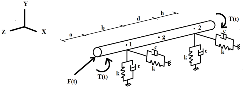
Dynamic model of a single spur gear transmission for predicting vibration measurements in bearing 1.
Kinematic analysis considering small angle


Deriving equations (3) and (4) we get:


From equation (4)

Substituting equation (7) in (3) we get:


Deriving equations (7) and (10)


Substituting equations (10), (12), and (13) in (1)


If


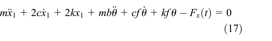
The variables in the system of equations (17)–(20) are
The radial stiffness (λ) according to El-Sayed 17 is calculated by equation (21). W is the load on the bearing and L is the stiffness factor which depends on the bearing dimensions. D0 and D i used in equation (22) are the outer and inner diameters of the bearing in mm. C i and C0 are the curvatures of the ball and raceway in the rolling and vertical planes, inner and outer ring, respectively. M i /m i and M0/m0 are constants which depend on the Poisson’s ratio of the material of the inner and outer rings respectively, as shown in Figure 5.

M/m values from the work of El-Sayed. 17
The ball bearing selected for the model was UCP 205, which is a bearing for a shaft with a diameter of 25.4 mm. The parameters of the UCP 205 bearing required to estimate the radial stiffness are given in Table 4. A radial stiffness curve as a function of load was obtained because the stiffness value depends on the load applied. Figure 6 shows the radial stiffness for the selected bearing under various load conditions. A constant torque of 3.25 Nm has been taken as the reaction torque, therefore the estimated load on each bearing is close to 60 N. Therefore the stiffness adopted for the model is
UCP 205 bearing’s parameter.


Radial stiffness of the selected ball bearing (UCP 205).
The model also requires an estimation of the damping. Calculating the actual damping is not a simple process, it depends on the lubricant and the friction at the contact points due to internal motion. Although there are various studies available to estimate bearing damping, most are specific to the application under consideration. A rough estimation is proposed by Krämer,
23
he concluded that the bearing damping is in the range


Values for mass, inertia, and lengths are required in the model. The system of non-homogeneous second-degree differential equations (17) and (20) is solved and an acceleration versus time signal is obtained. The Fourier transform is then applied to this signal to obtain the frequency spectrum, as shown in Figure 7 for the aligned condition. As expected, there are well-differentiated peaks at the GMF of 84.7 Hz and its multiples, as shown in Figure 7. The basis for comparing the misalignment conditions is the aligned frequency spectrum. In a previous work, 7 an indicator was proposed to calculate the change in the frequency spectra of gears with shaft misalignment. This indicator, shown in equation (23), calculates the deviation of the peaks of two spectra. In equation (23)n is the number of samples; y are the values of the spectrum to be compared, and z are the value of the base spectrum.

These spectra are first smoothed so that the peaks at the turning frequencies and their multiples, and at the gear frequencies and their multiples, stand out. To do this, the maximum value is taken every 5 Hz, thus eliminating the information that is not of interest, which may be noise in the signal and could affect the real value of the indicator if not suppressed. Combinations of axial and radial misalignment without angular misalignment were used.

Frequency spectrum of the simulated acceleration signal in the aligned condition. Peaks at GMF (84.7 Hz) and at 2XGMF, 3XGMF, 4XGMF, and 5XGMF multiples.
A surface response for the selected levels is shown in Figure 8. As reported in the work of Khan et al., 5 increasing the radial misalignment alone reduces the vibration levels. In this case, the changes in the spectrum are significant (15%) when the radial misalignment is 1.5 mm, which is half the module. This tendency remains for the combination of axial and radial misalignment. All combinations of axial-radial misalignment, including zero, produce a decrease in the percentage change in area, as shown in Figure 8. This confirms the initial hypothesis that the increase or decrease in vibration levels is strongly related to the force received by the shaft due to the contact of the gears: in the case of radial misalignment, this force should decrease as the distance between the centers increases, since the torque remains constant. Since the acceleration signals obtained are in the x-y plane, it is understandable that the effect of axial misalignment is not significant, as can be seen in Figure 8. For the spur gears considered in this study, the line of action between meshing teeth lies entirely within the transverse plane, which coincides with the principal load-bearing direction. Moderate axial misalignments do not significantly alter the orientation of this contact line, meaning that the dominant tangential force component remains aligned with the model’s assumed direction of motion. As a result, the measured acceleration—taken along this axis—shows minimal variation under axial misalignment conditions. This behavior explains why the influence of axial misalignment on the vibration response is comparatively small, despite its geometric presence in the experimental setup.

Percentage change in spectrum for combined axial and radial misalignment without angular misalignment.
The change from zero radial misalignment to 1.5 mm radial misalignment with any axial misalignment produces a reduction in the spectrum of approximately 15% compared to the base spectrum. This means that the radial misalignment can be diagnosed by modeling or vibration measurements, either when it is acting alone or when it is combined with the axial misalignment, by determining or reading the vibrations in one of the bearings in the vertical direction, for a horizontal configuration of the gears. It is interesting to note that, unlike misalignments due to deflection or deformation of the teeth, which cause an increase in vibrations, in the case of the misalignments studied, which are products of changes in the position of the shafts, the effect is generally reversed, that is, the vibration levels are reduced. Although the percentage change in the acceleration spectrum is reduced for axial-radial combinations, it is not desirable to have misalignments in the system because of the transmission errors and the increased stress they can generate.
In order to estimate the significant variables and interactions, an analysis of variance (ANOVA) was carried out on all the results of the combinations of levels examined in Table 3. Radial (B), the radial-angular interaction (BC), the radial variable squared (B2), the angular variable squared (C2), and the interaction of axial squared multiplied by angular (A2C) were the variables with a p-value less than 0.05. Equation (24), with a coefficient of determination of 0.87, is a regression that predicts the change in area of the spectrum for the combined misalignments studied. The equation is coded, which is important for comparing the effect of each element in the regression, so that high levels of the factors are coded +1 and low levels −1.
More than knowing an exact prediction of the vibration, what is really important is to know its tendency according to the changes in the input variables and the conclusions that can be derived from this behavior. In this way, the negative sign of the coefficient of the radial variable means that an increase in the radial misalignment causes a decrease in the acceleration spectrum. The negative sign of the squared angular variable (C2) means that as the angular misalignment increases, the acceleration spectrum decreases relative to the base. This means that increasing positive yaw offsets will decrease the percentage change in the spectrum, and increasing the absolute value of negative yaw offsets will decrease the percentage change in the spectrum. The value of the coefficient of each element in the regressions is related to the contribution of that element to the response variable; the sum of the contributions of the elements where the angular misalignment occurs is the largest. As expected, axial misalignment has no significant effect on the vertical vibrations for a horizontal gear configuration. Therefore, axial misalignment does not appear as an individual variable in the regression.
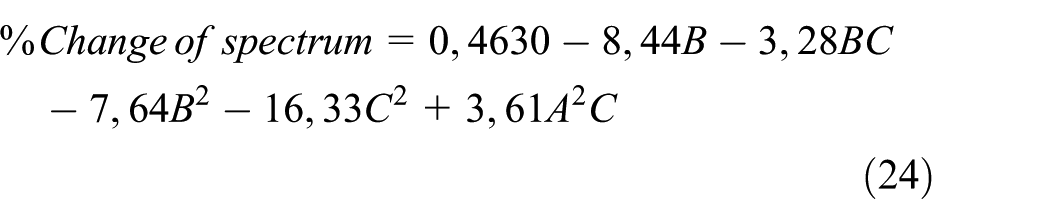
Figure 9 shows the percentage change in spectrum for two angles, a positive angle (2.69°) and a negative angle (−2.69°) for the values obtained in the developed hybrid model. The figures are response surfaces of equation (24). The regression of the percentage change in spectrum shown in equation (24) is obtained by combining the three levels of each of the three factors shown in Table 3, a total of 27 conditions. The operating conditions and the misalignment values of the combinations of the extreme values of these runs correspond to the misalignment values that were experimentally analyzed in a previous work. 7 The experimental runs are presented in Table 5. To compare the change of a spectrum from a misaligned condition to an aligned condition, the same indicator was used for both the experimental runs and the points evaluated in the hybrid model. Thus, for validation of the proposed model, the results of the experimental runs may be compared with the points of the model by the percentage of spectrum modification. The results are shown in Figure 10, where all the experimental points were compared with the values obtained from the model.

Percentage of change of spectrum for a 2.69° of yaw misalignment (left) and −2.69° of yaw misalignment (right) in the developed hybrid model.
Order of experimental tests.


Comparation of the percentage of change of spectrum for experimental and modeled cases. The points in x-axis are those shown in Table 5 in the same order.
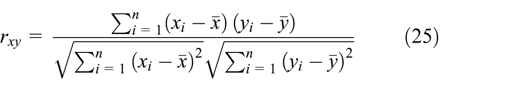
The points used for comparison are shown on the x-axis and are the same as those shown in Table 5 in the same order. Pearson correlation coefficient is calculated for comparing quantitatively experimental and simulated results. In the equation (25) n is the number of samples, x is one of the data to compare and y is the second one,
Since the tangential force predicted by the model acts in a single motion direction within the bearing, the acceleration was evaluated exclusively along that axis. This simplification may introduce discrepancies with the experimental results, as agreement would require perfect alignment between the tangential force vector and the accelerometer’s sensing axis. In practice, such alignment may not be achieved due to slight inclination during sensor installation or minor positioning errors in gear meshing. Even a small deviation between the theoretical and actual gear positions can alter the magnitude of the tangential force.
In the analytical formulation, the bearings were modeled as linear systems with stiffness k and damping c. The procedure adopted to estimate k, while reasonably accurate, is subject to a certain error margin that may contribute to the observed differences between model predictions and measurements. A similar situation arises for the damping coefficient ccc: although it is, in principle, load-dependent, treating it as such would render the force estimation problem intractable, as the force itself is the target variable. Given the relatively small variations in force, ccc was assumed constant. This assumption is acceptable at the present stage, where the focus is not on reproducing the exact acceleration magnitude, but rather on assessing the influence of tangential force variations on the measured vibration response.
Furthermore, the intentional misalignments introduced in the referenced experimental setup are themselves subject to implementation errors, which further contribute to differences between the modeled and measured results.
The torque applied in the simulation was assumed to be constant, which may lead to differences from the experimental values. Although the hydraulic system used in the referenced experimental work is highly stable, small fluctuations can occur during testing, causing slight variations in this value, in addition to minor losses that may arise.
The discrepancies between the predicted and experimental results can be explained by the simplifying assumptions made in the model, as well as to inherent experimental errors. In any case no difference is greater than 15% and the average of the differences is 10.5%. Figure 11 shows a diagram of the proposed hybrid model. The process begins with the definition of basic design parameters for the transmission system, including the geometric parameters of the gears such as the module, number of teeth, and material of both the pinion and the driven gear. These parameters are essential for the CAD model.
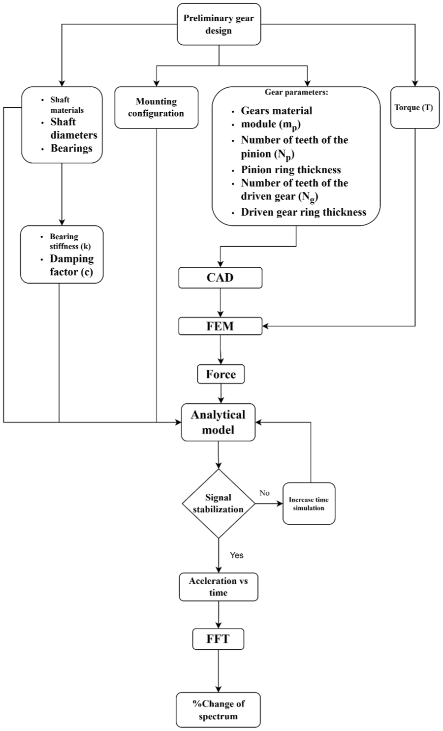
Diagram of the proposed hybrid model for estimating accelerations at the bearing base of spur gears under combined misalignments.
For the finite element analysis, both the CAD model and the applied torque value are required. This model generates force values over time, which, along with the stiffness and damping factor of the bearings and the material properties of the shafts, allow the analytical model to obtain acceleration versus time values at the bearing base. Subsequently, a spectrum is obtained using the Fast Fourier Transform, enabling the calculation of the percentage change in the spectrum relative to the aligned condition.
Model applicability and limitations
The proposed hybrid model, while showing strong agreement with experimental results (R = 0.98), has been developed under a set of idealized assumptions that constrain its applicability. The current validation assumes constant rotational speed and torque, which makes the model most suitable for steady-state analysis; transient regimes such as startup, shutdown, or load variations would require incorporation of time-dependent torque and mesh-stiffness effects. The numerical simulations assume rigid shafts and ideal gear tooth geometry, thereby neglecting potential influences from shaft flexibility or manufacturing tolerances beyond the intentional misalignments studied.
Tooth contact is modeled as frictionless, omitting lubrication effects and surface wear that could alter vibration signatures in long-term operation. Moreover, the node-to-surface contact formulation, although computationally efficient, can underestimate localized stresses under extreme misalignment conditions compared with surface-to-surface approaches. Bearing properties are represented by constant linear stiffness and damping values obtained under low-load conditions; at higher loads or speeds, nonlinear bearing behavior may become significant. In practice, bearing damping also depends on lubricant properties and temperature, which are not captured here.
A further limitation of the present study is that pitch-type angular misalignments (rotation about the transverse axis) were not generated in the simulations or experimental runs. Pitch misalignments introduce thrust components that predominantly excite axial vibration modes; therefore, the current model does not capture the axial response associated with pitch errors and cannot be used to diagnose pure pitch misalignment effects. The misalignment set analyzed (axial, radial, and yaw) was chosen to match the referenced experimental campaign, but extension to include pitch remains necessary for a complete assessment of axial vibration phenomena.
Within these bounds, the model remains a reliable and computationally efficient tool for design-stage analysis and misalignment trend prediction in spur gear systems.
Conclusion
A hybrid model has been proposed for the estimation of acceleration spectra at the base of one of the bearings of a single stage spur gear transmission system in which the pinion and driven gear are in overhung mounting. The model is based on a simulation in finite element software to estimate the force transmitted by the gears to the shaft. This force signal is one of the inputs to an analytical model that predicts vibrations in one of the bearing bases. This model allows more working points to be explored than could be achieved experimentally.
The results obtained with the model compared with those obtained experimentally in a previous work coincide with a correlation level of 0.98. For each value evaluated, the differences obtained do not exceed 15%. In this way, the proposed method for estimating the change in the acceleration spectrum in the bearing bases of single-stage gearboxes with shaft misalignment is a good way of estimating this variable. Running a fully simulated model through dynamic analysis would require much more computational resources and time.
Although a regression model was obtained for the percentage change in spectrum, it is important to emphasize the contributions of each type of misalignment and their interactions. For combined misalignments, angular and radial misalignments and their quadratic effects are the main contributors to the percentage change in spectra. This is to be expected as axial misalignments do not cause significant changes in the tangential force of the gears.
Footnotes
Handling Editor: Fatih Karpat
Author contributions
Rafael Tuirán: Methodology, Formal analysis, Writing-Original Draft. Heriberto Maury: Methodology, Formal analysis. Héctor Águila: Methodology, Formal analysis. José Oñate: Methodology, Resources, Data Curation. Hugo Álvarez: Resources, Data Curation.
Funding
The authors received no financial support for the research, authorship, and/or publication of this article.
Declaration of conflicting interests
The authors declared no potential conflicts of interest with respect to the research, authorship, and/or publication of this article.