
Abstract
Structure control techniques have been used to control vibrations in civil structures from natural and other types of hazards for many years. However, it is difficult to achieve effective reduction in the dynamic responses of the structures under seismic excitation for the reason that earthquake generates huge kinetic energy in short time interval, unless adopting very large conventional vibration reduction devices to absorb so much energy. A kind of mass damper, the accelerated oscillator damper is proposed in this article to improve the performance of vibration absorbers. The kinetic energy of the secondary mass is proportional to the square of its velocity, and speed of the secondary mass can be amplified through the transmission of the accelerated oscillator damper system, so that according to the principle of energy conservation, the more kinetic energy the secondary mass gets from the whole system, the more kinetic energy the building will lose. The proposed accelerated oscillator damper system is superior to the tuned mass damper system for short input durations and the maximum seismic response. Moreover, the investigation also shows that the transmission ratio plays a more significant role for vibration absorption than the mass ratio.
Keywords
Introduction
Structure control techniques, including passive, active, hybrid, and semi-active control systems, have been developed to protect civil structures from natural and other types of hazards. As for a tuned mass damper (TMD) system, a large amount of structural kinetic energy is transferred to TMD and then dissipated by the damping when the primary structure is under the action of vibration loads. Therefore, the security and habitability of the primary structure are greatly improved. 1 TMDs are effective in reducing the response of structures to harmonic 2 or wind 3 excitations. In order for TMDs to be effective to reduce structural vibration subjected to earthquake excitations, large mass ratios must be used, especially for structures with higher damping ratios, 4 and TMDs are ineffective in reducing the maximum seismic response of tall buildings. 5 If the major frequency content of the excitation is away from the primary structure’s natural frequencies, the TMD may not cause much response reduction. 6 Therefore, when unpredictable major frequency content of an earthquake deviates from the frequency of the TMD, the TMD may not work effectively in the earthquake.
The adoption of multiple tuned mass dampers (MTMDs) has been proposed to enhance the control performance of structures.7–10 Park and Reed’s 11 research shows that the uniformly distributed mass damping system is more effective in reducing the peak dynamic magnification factor (DMF) and more reliable when an individual damper fails. Kareem and Kline 12 found that the MTMDs with an optimal frequency range are more effective than single TMDs for a wide range of damping.
Active TMDs are introduced with external source of power to produce additional forces on civil structures. So, the active TMD system is effective in reducing seismic response 13 and is more robust to tuning error with the suitable use of feedback. Various control algorithms have been developed for active TMDs.14–17 An intelligent rule-based control method 18 was studied and numerical examples were used to demonstrate that the rule-based control method has equivalent or better performance than the traditional linear quadratic regulator (LQR) control method. Although active TMD system is more effective in reducing seismic response, the high-performance actuators and hydraulic power sources are still important. 13 During a severe seismic event, the external power to a structure may be cut-off, 19 and the control schemes relying on large external power supplies are inefficient. Consequently, one of the main obstacles 20 for the application of active control system in structures is the reliability of the power supply.
The semi-active TMD uses a small amount of external power to adjust the damping. By changing the structural parameters of damping and stiffness, the vibration is attenuated indirectly. Semi-active devices provide the reliability and fail-safe property of passive devices and have the adaptability of active devices. 21 Simulation studies by Hrovat et al. 22 show that the semi-active TMD system is superior to conventional passive control systems and comparable to active systems. Consequently, semi-active TMDs are often utilized to control wind-induced vibrations in tall buildings. Magnetorheological (MR) dampers, 19 which are often used in semi-active control systems, are new type of devices with low power requirements suitable for seismic vibration control.
For most of the above vibration reduction techniques, it is difficult to achieve effective reduction in the dynamic responses of the structures under seismic load for the reason that earthquake generates huge kinetic energy in short time interval, whereas conventional vibration reduction devices are not effective enough or limited by structure space arrangement to absorb so much energy.
In this study, a kind of effective vibration reduction system was proposed depending on the following two respects: (1) it is a passive structural control system without any external source of power to produce additional forces on the structures; (2) when the structure is subjected to earthquake excitation, kinetic energy of the structure can be transmitted to the secondary mass efficiently and quickly, such that the primary structure will lose kinetic energy as much as possible to reach the target of decreasing vibration. An accelerated oscillator damper (AOD) device was proposed to improve the damper’s performance. The kinetic energy of the secondary mass is proportional to the square of its velocity, and speed of the secondary mass can be amplified through the transmission of the AOD system (following the principle of Archimedes’ lever). According with the principle of energy conservation, the more kinetic energy the secondary mass gets from the whole system, the more kinetic energy the building will lose. 23
The motion equations of the AOD system will be established using the Lagrange principle. Analytical solution, simulation model, and finite element (FE) results will be obtained and compared to find the mechanical properties of the proposed structural control system. The authors evaluate the performance of the system when transmission ratio and mass ratio vary. In a numerical example of suspension bridge, feasibility and effectiveness of the AOD system will be investigated, and TMDs and viscoelastic dampers will be compared with the AOD system in the same bridge.
Derivation of motion equations of the structure–AOD system
The structure–AOD system can be modeled as a single-degree-of-freedom system to which AODs are attached as appendages at a suitable location. The AOD device is composed of secondary mass, transmission device, spring, damper, and connecting rod. As shown in Figure 1, the vibration of the primary structure is transferred by a transmission device by the connecting rod to amplify the velocity of the primary structure through the transmission to yield higher speed of secondary mass. The transmission device is a rack and pinion system comprising a pair of gears which convert linear motion into rotational motion. A linear “gear” bar called “the rack” engages teeth on a circular gear called “the pinion”; linear motion applied to the rack causes the pinion to move relative to the rack, thereby translating the linear motion of the rack into rotational motion. The pinion or gear set amplifies the speed and then transferred to the secondary mass by another rack. The secondary mass m2 is connected to the static structure with spring and damper. So, the secondary mass can absorb the kinetic energy from the primary structure. While increasing the transmission ratio, the secondary mass gets more kinetic energy from the primary structure. Due to the principle of conservation of energy, the more kinetic energy the secondary mass gets from the whole system, the more kinetic energy the building will lose. In this way, the vibration of the primary structure can be attenuated.

Schematic demonstration of structure–AOD system.
Assume that the structure is a single-degree-of-freedom system without the influence of friction; the transmission is idealized without energy dissipation; and the structure and the damper are linearly elastic. The equation of motion of the structure–AOD interaction system contains a number of parameters that govern the behavior of the structural vibration reduction. Figure 1 schematically represents the primary structure to be controlled, specified by the first modal mass, m1, along with the absolute displacement, x1, the primary structure spring constant, k1, damping constant, c1, and external force acting on the structure, f(t). Also shown in Figure 1 is the AOD and its corresponding values of x2, k2, and c2. The transmission ratio of the AOD system is r, defined as the amplifying factor of the motion from the primary structure to the secondary mass. If r is larger than 3, it is appropriate to design a two-stage rack and pinion system.
Setting the origins at the static equilibrium position of the primary structure m1 and the secondary mass m2, respectively, generalized coordinate system is established. Taking the primary structure and the AOD system as a whole, the kinetic energy T and elastic potential energy V of the whole system can be expressed as follows

where

Damping forces of the system are assumed linear, so that the Rayleigh dissipation function D is expressed as

Taking equation (3) into equations (1), (2), and (4), we obtain that


Choosing generalized coordinates
In equation (8),

where f(t) is the exciting force acting on the primary structure. In the case of seismic excitation, x1 denotes relative displacement and a dot over x1 represents its time derivative. Accordingly,

The whole system is equivalent to a single-degree-of-freedom system, because the displacement and velocity of m1 and m2 are constrained according to certain proportion by the transmission. Equation (10) is a typical dynamic differential equation of a single-degree-of-freedom system. In order to simplify the expression, denotes x1 as x in the following paragraphs, with the subscripts of the corresponding velocity and acceleration being removed. According to equation (3), the displacement, velocity, and acceleration of the secondary mass are r times than that of the primary structure, respectively. With new symbols substituting the mass items in equation (10) as

Equation (10) can be simplified as

M, K, and C are defined as generalized mass, generalized spring constant, and generalized damping coefficient, respectively. Equations (10) and (11) are the motion equations of the AOD system and its simplified form, respectively. If the forcing function is harmonically oscillating and acts only on the primary structure, it is given by

where

Damping coefficient
With x0 and v0 expressing the initial displacement and initial velocity of the primary structure, respectively, the final solution of the equation (12) can be expressed as

where

Numerical example and analysis
Equation (13) shows the analytical solution with a sine function exciting force acting on the primary structure. The AOD system can also be calculated by FE method and simulation analysis. A numerical example is given to verify the feasibility of the proposed three methods in the following paragraphs. The relevant parameters for the numerical examples are listed in Table 1.
Data for numerical examples.

Figure 2 shows the displacement curve of the primary structure controlled by the AOD system using FE method and analytical method, respectively. As can be seen in Figure 2, the results obtained by these two methods are almost the same. Analytical solution expresses obvious mechanics meaning and can be obtained from simple questions, whereas FE method can be used to solve complex problems.
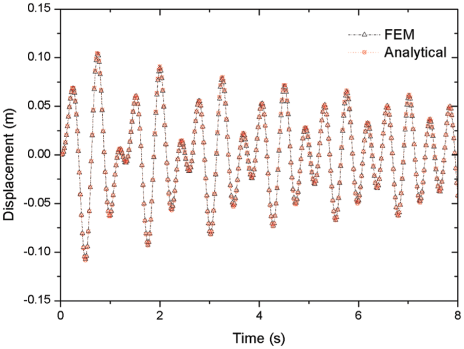
Displacement curve of the primary structure using analytical method versus FEM.
The modeling of a single-degree-of-freedom system with AOD device can be carried out by FE method. The simulation of the transmission device is very significant. A compatibility equation of displacement between the primary structure and the secondary mass must be established, that is, the secondary mass displacement equals r times of the primary structure displacement in their respective direction of motion.
Simulation analysis
MATLAB Simulink is used to simulate the dynamic behaviors of the AOD system. Suppose that F1 and F2 are, respectively, the internal force of the rod of the primary structure and the secondary mass connecting to the transmission device. The motion equations of m1 and m2 are established as


where a1 and a2 are, respectively, the accelerations of m1 and m2. Equation (15) is transformed to

The acceleration a1 is integrated from 0 to time t, we have the velocity

Simulation diagram.
Acceleration, velocity, and displacement are transformed to a2, v2, and x2 through the relation:
Each component of equation (16) is divided by m2, we get

Putting a2, v2, and x2 into equation (18), we get the formula expression of F2/m2. The internal force of the connecting rod on both sides of the transmission device meets Archimedes’ lever principle, so that
The result of simulation analysis is as the same as the results shown in Figure 2. It proofs that the working principle of AOD system can be simulated by simulation analysis.
Dynamic behaviors of the AOD system
The DMF of the AOD system
Effectiveness is defined as the reduction of the peak structural response under a given loading. For harmonic excitation, this is the peak DMF.
The solution of motion equation of the AOD system is equation (13). The first part of it is pure free vibration determined by initial conditions, the second part is decaying vibration due to damping, and the third part is pure forced vibration of which the amplitude and period do not change with time. According to equation (14), the amplitude of pure forced vibration is expressed as follows

The static displacement caused by the maximum interference force P is denoted as
From above, we also know that
The critical damping ratio of the system is defined as
The decreasing factor of the AOD system
The AOD system has the same motion equation form as the general single-degree-of-freedom system. The only difference is that the right-hand side is
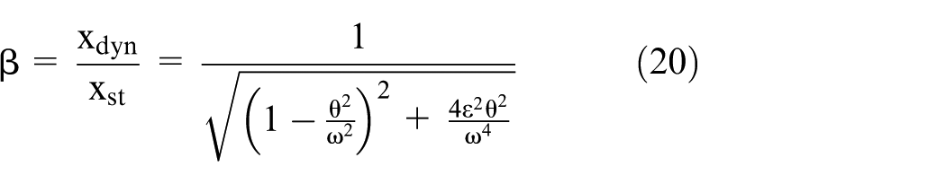
In general, the seismic response reduction rate β 24 is defined as

where e0 and e1 are the uncontrolled and controlled displacement response, respectively.
If the secondary mass m2 and the secondary spring k2 are taken away from the AOD system, that is, m2 and k2 equal to zero, this is the condition with no vibration reduction device. Defined as a reference criterion of the amplitude of the mass m1, influence of the vibration reduction rate is examined in Figure 4 by varying the value of mass ratio (0.02, 0.04, 0.06, 0.08, 0.10) while transmission ratio varying (r = 2, 3, 4, 5, 6, 8, 10). In this manner, comparison was made based on the vibration reduction rate of displacement of various cases, not absolute displacement. For common TMD system, the mass ratio is between 1% and 4%. In the proposed AOD system, effect of the mass ratio obeys similar rule as the TMD system, but the transmission ratio appears more effective in vibration reduction.

Vibration reduction rate of different mass ratios by different transmission ratios.
Further research on different transmission ratios of the AOD system indicates that
r = 0, this system degenerates to a single-degree-of-freedom oscillator system with parameters of m1, k1, and c1;
0<r<1, the secondary mass system is involved in vibration reduction, but the effect is so small that can be ignored;
r = 1, the response characteristics of an AOD are equivalent to a spring oscillator system with one block mass of m1 plus m2, two parallel springs of k1 plus k2, and two damper of c1 plus c2;
r > 1, the transmission device can improve effect of the vibration control;
r > 2, the vibration reduction effect is greatly obvious.
For an example, adopting the parameters of Table 1, when r = 5, the amplitude can be reduced to half of the original. With the increase in the transmission ratio r, the amplitude decreases rapidly. The amplitude can be reduced to 20% of the original when r = 10.
Mechanical behavior of the AOD device
Under periodic external force function:
Figure 5(a) shows the vibration of a single-degree-of-freedom structure system with AOD and the same structure without artificial damping. Figure 5(b) shows the result of the structure–AOD system and typical TMD with parameters m2 and k2 as the same as the AOD system, respectively.

Structural response under periodic external force: (a) AOD and no damping controlled; (b) AOD and TMD controlled.
Inputting the seismic wave with the peak acceleration as 0.37g shown in Figure 6, the calculation result of the structure with AOD and without damping is shown in Figure 7(a), and Figure 7(b) shows the calculation result of the structure with typical TMD. Figure 7(a) shows that AOD is very effective in structure vibration reduction under seismic load. Figure 7(b) shows that vibration attenuation efficiency of the AOD is significantly better than TMD. The transmission ratio is 4 in the above calculation.

Seismic wave with peak acceleration as 0.37g.
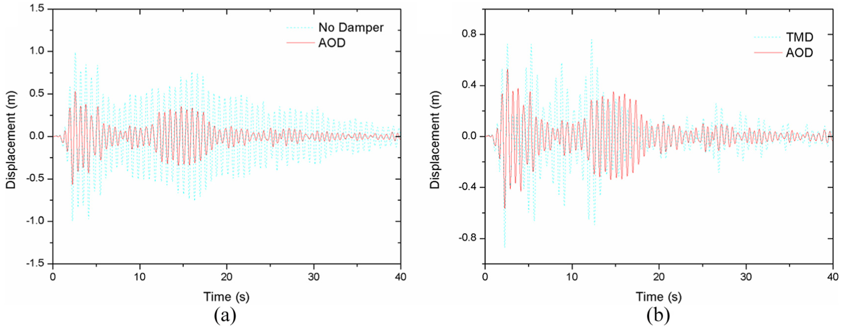
Structural response under seismic load: (a) AOD and no damper controlled; (b) AOD and TMD controlled.
The effectiveness of conventional TMD’s 25 is low for short input durations and monotonically approaches the stationary limit. Simulation investigations in this article show that the proposed AOD system is superior to TMD for short input durations and the maximum seismic response.
Illustrative examples and analyses of results
Taking a suspension bridge (Xinghai Bay Bridge, Dalian, China) as an example, the following section investigates the effectiveness of AOD in vibration control. This is an earth-anchored suspension bridge with main span of 460 m and side span of 180 m as shown in Figure 8. The stiffening girder is a double-layer steel truss structure (Figure 9). The design parameters of the bridge are listed in Tables 2 and 3.
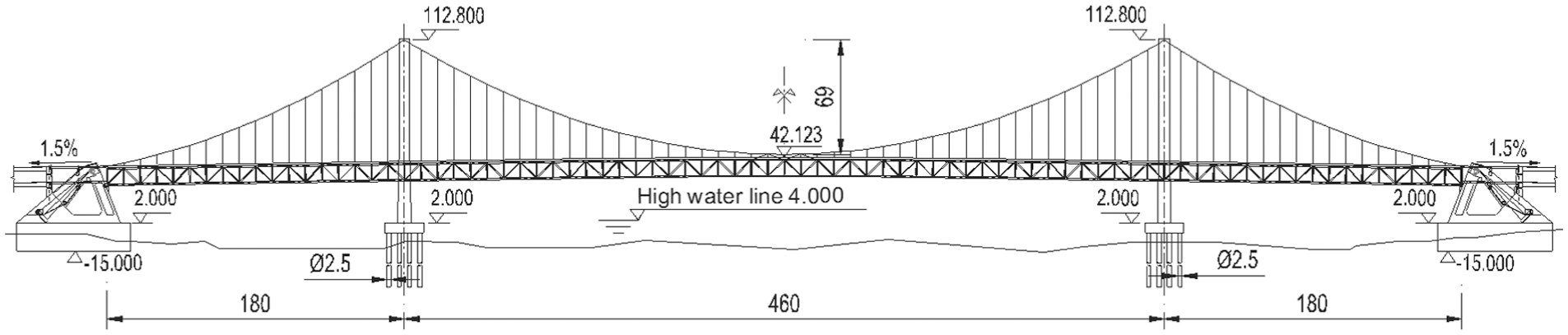
General layout of Xinghai Bay Bridge (m).

Stiffening girder section drawing (mm).
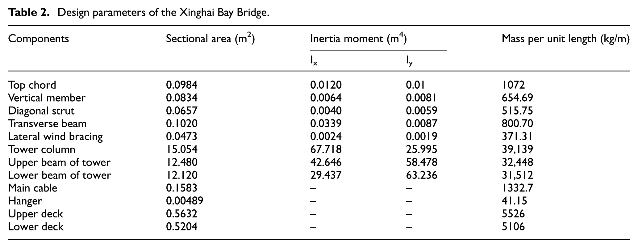
Design parameters of the Xinghai Bay Bridge.
Material and AOD design parameters.
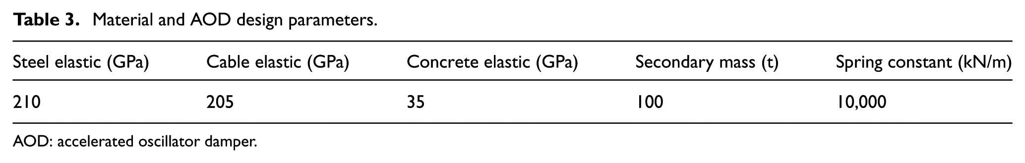
AOD: accelerated oscillator damper.
Two vibration control schemes ware proposed in the preliminary design. One of them is using eight viscoelastic dampers to connect the stiffening girder to the anchors and towers, respectively, with maximum output force of 2000 kN and the other one is using four AOD devices at the anchors with secondary mass of 100 t, the speed ratio of the transmission of 8 between the secondary mass and anchor. In order to demonstrate the superior vibration attenuation capacity of the transmission and mass spring system of the AOD device, we can neglect the function of the AOD damper, which is relatively less functional in the AOD system. Therefore, in the following analysis, the parameter of the AOD damper is zero.
As depicted in Figure 10, the girder is connected to the transmission device by a connecting rod. There is a rack on the connecting rod. The rack is essentially a linear gear which converts linear motion into rotational motion of the pinion or gear set. The pinion or gear set amplifies the speed and then transferred to the secondary mass by cables. The secondary mass is connected to the anchor with springs and dampers.
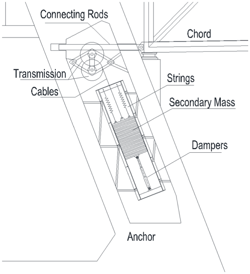
Drawing of AOD system in a suspension bridge.
The authors studied the effect of utilization of the AOD system and viscoelastic dampers under earthquake loading. The El Centro earthquake records were used in this analysis. Figure 11 shows the vibration of the girder without artificial damping; the vibration when viscoelastic dampers are employed; the vibration of the girder controlled by the AOD. The peak displacement of the girder without any vibration control is 0.22 m; adopting eight viscoelastic dampers at the anchors and the towers, respectively, the maximum displacement is reduced to 0.12 m; using the AOD system at the anchors, the girder displacement is limited to 0.05-m range.
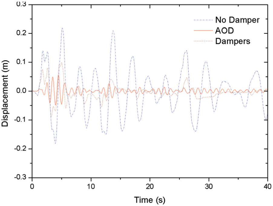
Damping effect of the Xinghai Bay Bridge under earthquake load.
Yang et al. 24 adopted MR dampers in the Pengsheng Bridge, a suspension bridge with 350 m main span. Their studies show that the seismic response reduction of the peak displacement is not obvious at the beginning of earthquake, even the peak value increases rapidly. However, with the increasing of input current of the MR dampers, the peak displacement decreases significantly after a few seconds. Investigation in this article also shows that the AOD system is more effective than MR dampers in reducing peak displacement of seismic response.
Conclusion
The proposed AOD mass damping device is an efficient vibration reduction system, which can be utilized in seismic mitigation of civil structures. The factors influencing the response of a structure equipped with a few AODs include the structural dynamic characteristics, ratio of the secondary mass to structural mass, transmission ratio, and the frequency range of AODs.
The AOD system has the same motion equation form as the general single-degree-of-freedom system. It is equivalent to the general single-degree-of-freedom vibration excited by the force being reduced to the original
In the proposed AOD system, effect of the mass ratio obeys similar rule as the TMD system, but the transmission ratio appears more effective in vibration reduction. As for the transmission ratio r > 2, the AOD device can achieve very ideal damping effect. In general, the mass ratio of the AOD system can be selected below 1%.
The AOD system is superior to TMD for short input durations and the maximum seismic response. It even works efficiently just with spring, transmission, and mass (except for viscoelastic damper) involved in seismic mitigation of bridges and other structures. The secondary mass ratio can be selected below 1%.
Footnotes
Handling Editor: Yun Lai Zhou
Declaration of conflicting interests
The author(s) declared no potential conflicts of interest with respect to the research, authorship, and/or publication of this article.
Funding
The author(s) received no financial support for the research, authorship, and/or publication of this article.