
Abstract
To date, considerable attention has been paid to the development of structural vibration suppression techniques. Among all vibration suppression devices and techniques, the tuned mass damper is one of the most promising technologies due to its mechanical simplicity, cost-effectiveness, and reliable operation. In this article, a critical review of the structural vibration suppression using tuned mass damper technology will be presented mainly focused on the following four categories: (1) tuned mass damper technology and its modifications, (2) tuned mass damper technology in discrete and continuous structures (mathematical modeling), (3) optimization procedure to obtain the optimally designed tuned mass damper system, and (4) active tuned mass damper and semi-active tuned mass damper with the practical realization of the tuned mass damper technologies.
Keywords
1. Introduction
The tuned mass damper (TMD) technology, which was developed on the basis of a TMD system proposed by Frahm (1911), is one of the most promising vibration absorption methods to mitigate and control unwanted vibration. Its mechanical simplicity, cost-effectiveness, and reliable operation have made TMD powerful passive vibration control devices to provide effective and robust vibration suppression performance. TMDs are also named as tuned vibration absorbers (Thomson and Dahleh, 1988) as they are basically vibration absorber devices. Without any damping element, a TMD can completely absorb the vibration at the selected tuned frequency and bring the response of the host system to zero at that frequency. However, without the damping element in the TMD, the system becomes very sensitive to slight mistuned conditions. The inclusion of the damper will slightly increase the bandwidth around the tuned frequency and also decreases the response of the system in mistuned conditions through dissipation of energy by the damping element. To attain the best vibration suppression performance, the parameters (mass, damping coefficient, and spring stiffness) of the attached TMD system must be determined through a design optimization procedure.
The earliest research works on the optimal TMD design were presented by Ormondroye and Den Hartog (1928), Brock (1946), and Den Hartog (1956) for single-degree-of-freedom (SDOF) primary structures subjected to harmonic loadings and also by Crandall and Mark (1963) for random base excitations. Now, in civil engineering, the TMD system and/or its modifications have been successfully installed in slender skyscrapers, towers, and bridges, such as the John Hancock Tower (241 m) in Boston, the Citicorp Center (279 m) (Dupré, 1996) in New York, the Taipei 101 Tower (508 m) (Taipei-101.com.tw) in Taiwan, and the Millennium Bridge (Fitzpatrick et al., 2001) in London. In structural and mechanical engineering areas, Stefko (2002) introduced the TMD system in turbo engine’s turbine blades and Lyles (2008) and Griffin (2008) developed TMD system to solve the potential thrust oscillation problems. The TMD technologies (working principle) are also widely adopted in the suppression of vibration in cutting tool machine (Liu and Rouch, 1991; Rivin and Kang, 1992; Sims, 2007; Tarng et al., 2000).
Optimal TMD design is not a new topic, and the optimal methodologies and parameters of the optimal TMD system for SDOF main structures subjected to different loading conditions have been verified by several researchers since 1960s. Warburton (1982) published a review-type article focused on single TMD design. A comprehensive study on the theory and practice of TMD was presented in a book by Korenev and Reznikov (1993) and a review article published by Sun et al. (1995). However, steady streams of research articles still continue to appear in this area. This is mainly due to the fact that the practical applications of the TMD technologies push the researchers to establish effective methods to design the TMD system to provide the best vibration suppression performance.
Thus, the purpose of this article is to present a state-of-the-art review of the TMD technology mainly focusing on the research articles published after 90s, with particular emphases on the following four parts: (1) the concept of classical TMD and its main modifications, (2) the modeling procedure for discrete and continuous main structures with the attached TMD system, (3) the optimization procedures/methods for TMD design, and (4) practical realization of TMD technologies and the active/semi-active TMD systems.
Here, it should be noted that many research articles regarding the nonlinear properties of the TMD system have also been presented since 90s. One may utilize available nonlinear models to describe the nonlinear properties of the main structures and/or the attached damper and/or stiffness of the TMD system, such as the work presented by Alexander and Schider (2009), Viguié and Kerschen (2010), and Wang (2011). The most important issue for the nonlinear TMD compared with linear TMD is the nonlinear stiffness, which will totally affect the response curve, especially in the frequency domain because the natural frequency of the secondary is not constant. The number of research articles addressing nonlinearity is vast, and thus considering the scope of this research article, the review on the nonlinear properties of the TMD system will not be presented in detail.
2. TMDs and their modifications
This section will be focused on the basic design concepts of the TMD systems and their main modifications, as illustrated in Figure 1. For the sake of clarity, this section will be mainly concentrated on the SDOF main structures connected with different secondary structures, which are designed on the basis of the TMD technology. Typical TMD systems and their configurations. (a) Classical TMD system. (b) Composite tuned-mass-damper system (CTMD). (c) Distributed tuned-mass-damper system (DTMD). (d) Multiple degree-of-freedom tuned-mass-damper system (MDOF-TMD). Note: TMD, tuned mass damper.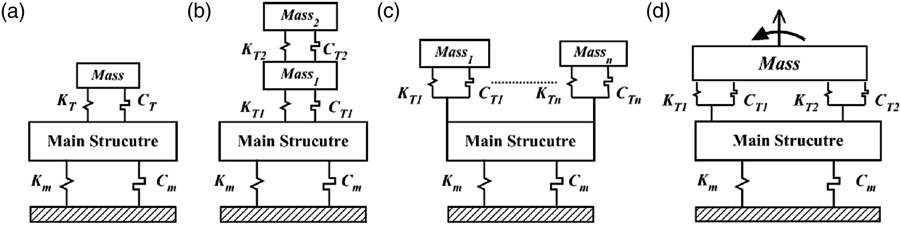
Fundamental tuned mass damper design and its basic modifications.
Note: TMD, tuned mass damper; CTMD, Composite tuned mass damper; DTMD, distributed tuned mass damper; DOF, degree-of-freedom; MDOF, multiple degree-of-freedom.
2.1. Classical tuned mass damper design
The classical TMD technology (Brock, 1946; Crandall and Mark, 1963; Den Hartog, 1956; Ormondroye and Den Hartog, 1928; Thomson and Dahleh, 1988), which dissipates vibratory energy through a set of damper and spring connecting a small mass (secondary system) to the main (primary) structure, has been illustrated in Figure 1(a). The natural frequency of the attached secondary system which is a TMD needs to be very close to the dominant mode of the primary structure, and thus a large reduction in the dynamic responses of the primary structure around the natural frequency of this dominant mode can be achieved. The fundamental working principle of the TMD system has been well-known, and since 90s, most of research articles related to the classical TMD system are mainly focused on the parameter sensitivity analysis, the response analysis, the different design (optimization) approach, and the design based on different loading conditions/types of main structures. For instance, Rana and Soong (1998) compared and investigated the vibration suppression performance and the optimal parameters’ sensitivity analysis of the optimal TMD systems obtained based on different optimal design approaches. Bekdas and Nigdeli (2013) studied the effectiveness of the mass ratio (ratio of the mass of TMD to the mass of main structure) on the vibration performance of the TMD system. Das and Dey (1992) presented the effectiveness of TMD system attached to bridge-type structures, which were modeled as SDOF or discrete multi-degree-of-freedom (MDOF) main structures. Krenk (2005) presented the frequency analysis of the TMD system to realize the effectiveness of the TMD system.
Some important issues for the classical TMD design, which have been conducted by many researchers, may be summarized as: The off-tuning of the stiffness of optimum TMD system from its design value has a significant influence on the performance of the TMD system. The off-tuning of the damping of optimum TMD system from its design value does not have much effect on the performance of the TMD system. The damping of the primary structure has a significant effect on the optimum stiffness of the TMD system, but not on its damping.
2.2. Composite tuned mass damper design
Based on the introduction presented by Nishimura et al. (1998), the modified TMD design, as illustrated in Figure 1(b), was named as the composite tuned mass damper (CTMD), and introduced by Yamada et al. (1988). Lewandowski and Grzymislawska (2003) investigated the CTMD system and added one controllable damper on the second TMD to improve the vibration performance of the CTMD system. Li and Zhu (2006) used the dynamic magnification factors (DMFs), which represent the magnitude of the structural response, as the optimization criterion to optimally design the CTMD system for SDOF main structures. Li (2006) also provided the detailed and comprehensive performance analysis of the CTMD system. Similar investigations have been conducted by other researchers in this area, such as the articles presented by Zuo (2009) and Stancioiu and Ouyang (2012), in which the CTMD has been named as the MDOF TMD.
2.3. Distributed tuned mass damper design
The other type of modified TMD design shown in Figure 1(c) was developed by Xu and Igusa (1992) and Igusa and Xu (1994) and named as multiple TMDs (MTMDs). Here it should be noted that to distinguish it from the design of the MTMDs based on multiple vibration modes of the main structures, such as the work presented by Manikanahally and Crocker (1991), the MTMD design based on one specific vibration mode (Igusa and Xu, 1994; Xu and Igusa, 1992), as shown in Figure 1(c), is referred to as the distributed tuned mass damper (DTMD) system.
The basic design concept of the DTMD system is to tune the natural frequencies of a set of small TMDs distributed around the designed vibration mode of the primary structure. It is noted that a TMD is a passive vibration device which is capable of attenuating vibration at specific tuned frequency. Thus, a single TMD can attenuate vibration in a small bandwidth around the tune frequency (which is generally the fundamental frequency of the host system). To increase the effectiveness and bandwidth, DTMD systems in which natural frequencies of set of TMDs are tuned at frequencies around the desired vibration mode of the primary structure. These tuned distributed TMDs are generally installed in a same location on the primary system where the vibration mode has the highest amplitude. It is noted that MTMDs can also be utilized to control vibration of multiple vibration modes of the primary structure in which each TMD is tuned to a specific vibration mode and is generally installed at the location where that vibration mode has the highest amplitude. Similar to that for the single TMD design, to attain the best vibration suppression performance, the mass, stiffness, and damping factor of the attached DTMD system should also be determined through a design optimization procedure.
Joshi and Jangid (1997) considered a uniformly distributed DTMD system for damped SDOF structures subjected to random base-excitation. Jangid (1995, 1999) designed a uniformly distributed DTMD system for both undamped and damped SDOF primary structure under harmonic base-excitation. Li (2000, 2002) presented a DTMD system to minimize the DMF of the primary system. The similar problems have also been investigated by Yamaguchi and Harnpornchai (1993), Bakre and Jangid (2004), Abe and Fujino (1995), Abe and Igusa (1994), Park and Reed (2001), Li and Liu (2003, 2004), Hoang and Warnitchai (2005), Zuo and Nayfeh (2005), and Li and Ni (2007). The main differences in those articles are (1) the different input mass distribution, which are the given parameters for the DTMD design in most of the articles; (2) the selected optimal objective function and its optimization procedure, which will be presented in detailed in Section 3. One of the extensions in this area is to design the DTMD system for torsional coupled system or main structures with rotary degree of freedom, such as the works presented by Jangid and Datta (1997), Wang and Lin (2005), and Li and Qu (2006).
2.4. Multiple degree-of-freedom TMD system design
The modification of TMD system illustrated in Figure 1(d) was named as the MDOF-TMD by Zuo and Nayfeh (2004), in which the attached TMD system contains both displacement and rotary degrees of freedom. The original design for this modification can be found in the works done by Gu and Xiang (1992) and Chang and Chang (1998). Here, it should be noted that the MDOF-TMD design is focused on one specific mode of the main structure.
2.5. Other modification of TMD system design
In Sections 2.1–2.4, the classical TMD and its main modifications have been introduced. There are still some other kinds of modifications based on the TMD technology as described in the following sections.
2.5.1. Modification focused on the classical TMD design
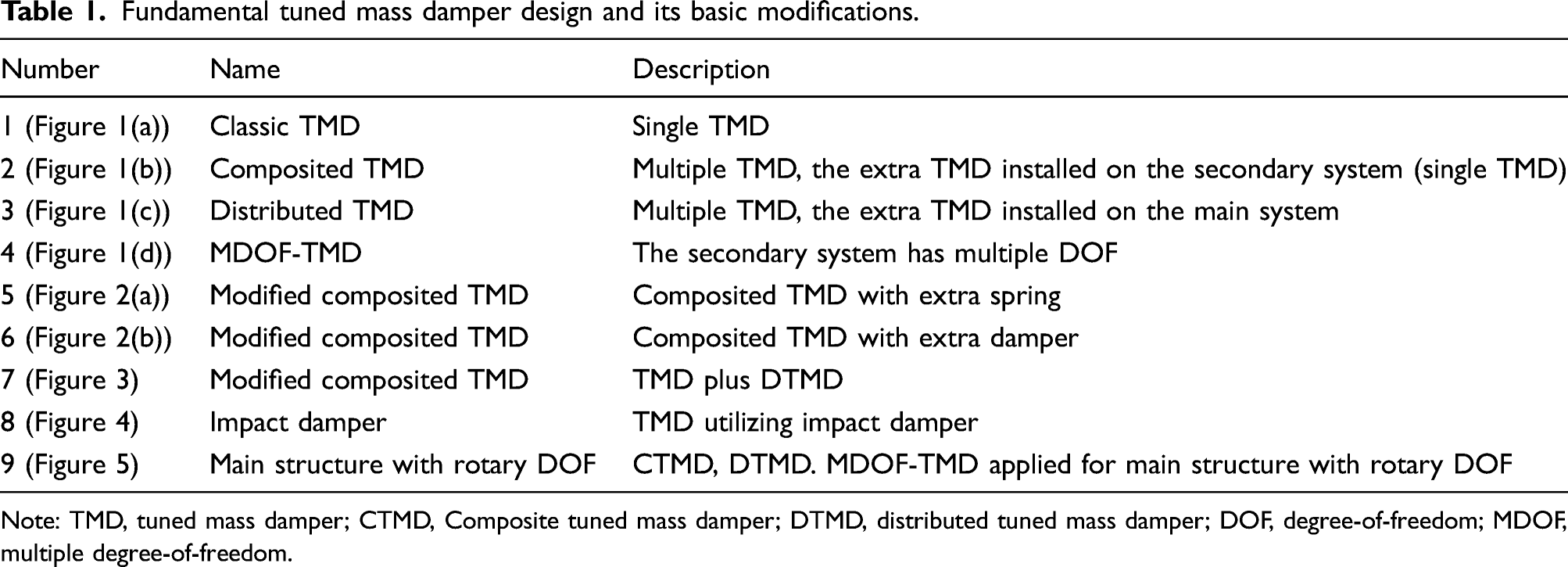
The first type of modification, as shown in Figure 2, is based on the classical TMD’s configuration. In Figure 2, M, k
0
, and c
0
represent the respective mass, stiffness, and damping of the primary structure, respectively, whereas m, k
1
, k
2
, c
1
, and c
2
represent the mass, stiffness, and damping of the attached modified TMD systems, respectively. Modifications based on the classical TMD design. (a) Adding stiffness with the damper of TMD. (b) Extra damper connected to the base. Note: TMD: tuned mass damper.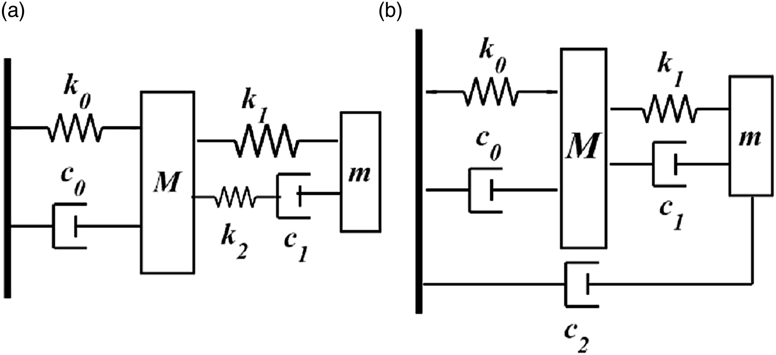
The modification shown in Figure 2(a) was named as “three-element TMD” by Anh et al. (2013). This is indeed the Maxwell model (Wiechert, 1889) in which a spring element and a dashpot are connected in series to represent a nonlinear TMD system. Satch (1991) and Gatade et al. (1996) presented the basic optimal design approach for these modified TMD systems and then Asami and Nishihra (1999, 2002) utilized these modifications to investigate the performance of active and active–passive tuned mass dampers. One can also adopt other nonlinear elements to replace the Maxwell model, such as the research work presented by Shaw et al. (1989), Gerges and Vickery (2003a, 2003b), Rüdinger (2006, 2007), Hwang et al. (2007), Alexander and Schider (2009), Ikago et al. (2012), and Garrido et al. (2013). As mentioned in the introduction part, the detailed nonlinear TMD system will be out of scope of the present article.
The variant design of the TMD system, as shown in Figure 2(b) was presented by Ren (2001). Liu and Liu (2005), Wong and Cheung (2008), and Marian and Giaralis (2014), presented the detailed investigation of this kind of variant design of the TMD system.
2.5.2. Different combinations based on the modified TMD design
Figure 3 illustrates one type of combined TMD design methodology, which is the combination of composite and distributed tune mass dampers shown in Figures 1(b) and (c). The original design was presented by Li and Zhu (2006). In Figure 3, M, k
0
, and c
0
represent the respective mass, stiffness, and damping of the primary structure; m, k
b
, and c
b
represent the respective mass, stiffness, and damping of the first-level attached TMD system; and m
n
, k
n
, and c
n
represent the corresponding mass, stiffness, and damping of each TMDs, utilized to construct the DTMD systems. One can utilize the basic design concepts shown in Figure 1 to obtain different types of vibration suppression devices based on the TMD technology. Therefore, many researchers focused on the vibration suppression performance comparison based on different types of combination of the classical TMD design and their modifications, as those shown in Figure 1. It should be noted that combinations of different TMD configurations provides the opportunity to either control several vibration modes simultaneously or to increase the bandwidth around the designed tuned frequency. The combination of TMD and DTMD. Note: TMD, tuned mass damper; DTMD, distributed tuned mass damper.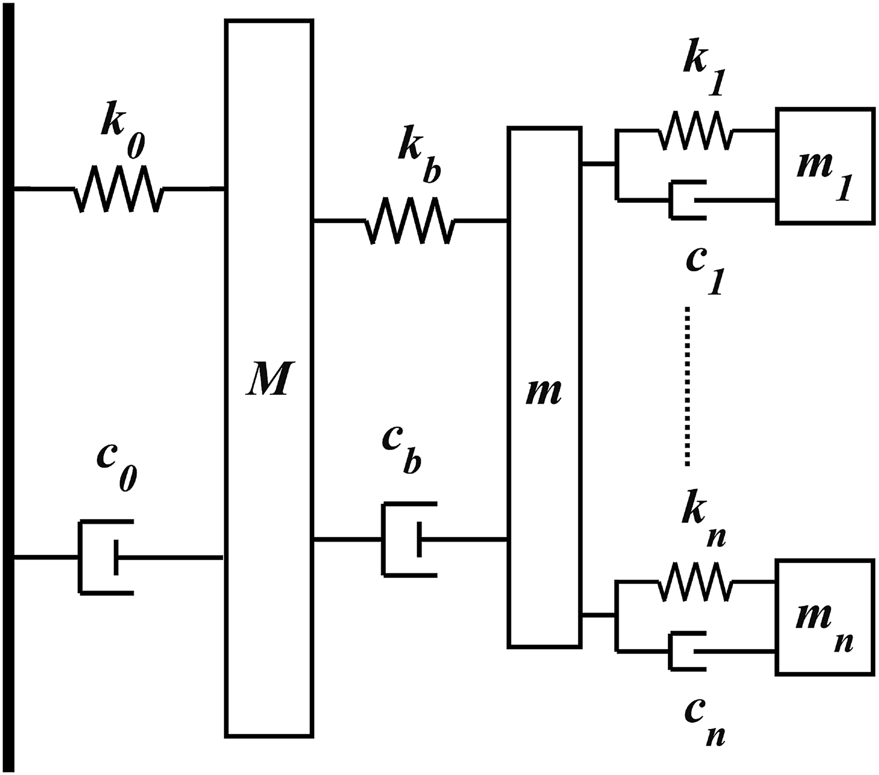
2.5.3. Impact damper with TMD system design
Impact damper is one of the effective damping methods. Barbara (2001) investigated the effectiveness of the TMD and the impact damper system, as shown in Figure 4(a), in which the stiffness (k1) and damping coefficient (c1) are both predefined. Cheng and Xu (2006) investigated the inner TMD systems, as illustrated in Figure 4(b), and extended the study to the beam structures. It is noted that inner tuned impact mass damper is basically a TMD in which the TMD mass can freely move and collide with the main mass system face-to-face through spring and damping elements of the TMD system. Duffy et al. (2000) proposed a combination structure, in which the impact damper has been combined with the pendulum system, as illustrated in Figure 4(c), and the natural frequency of the secondary system can be determined by the curvature of the pendulum system. Semercigil et al. (1992) also added a simple impact damper to the classical TMD system, as illustrated in Figure 4(d). All these studies show that utilizing an impact damper in which the TMD mass can freely move and impact with mass of the primary or secondary systems can not only decrease the vibration amplification of the main structure but also the attached secondary system, compared with the classical TMD design. Impact dampers with the TMD design; (a) Tuned-impact damper; (b) inner tuned-impact mass damper; (c) tuned pendulum type impact damper; (d) impact damper with the classical TMD design. Note: TMD: tuned mass damper.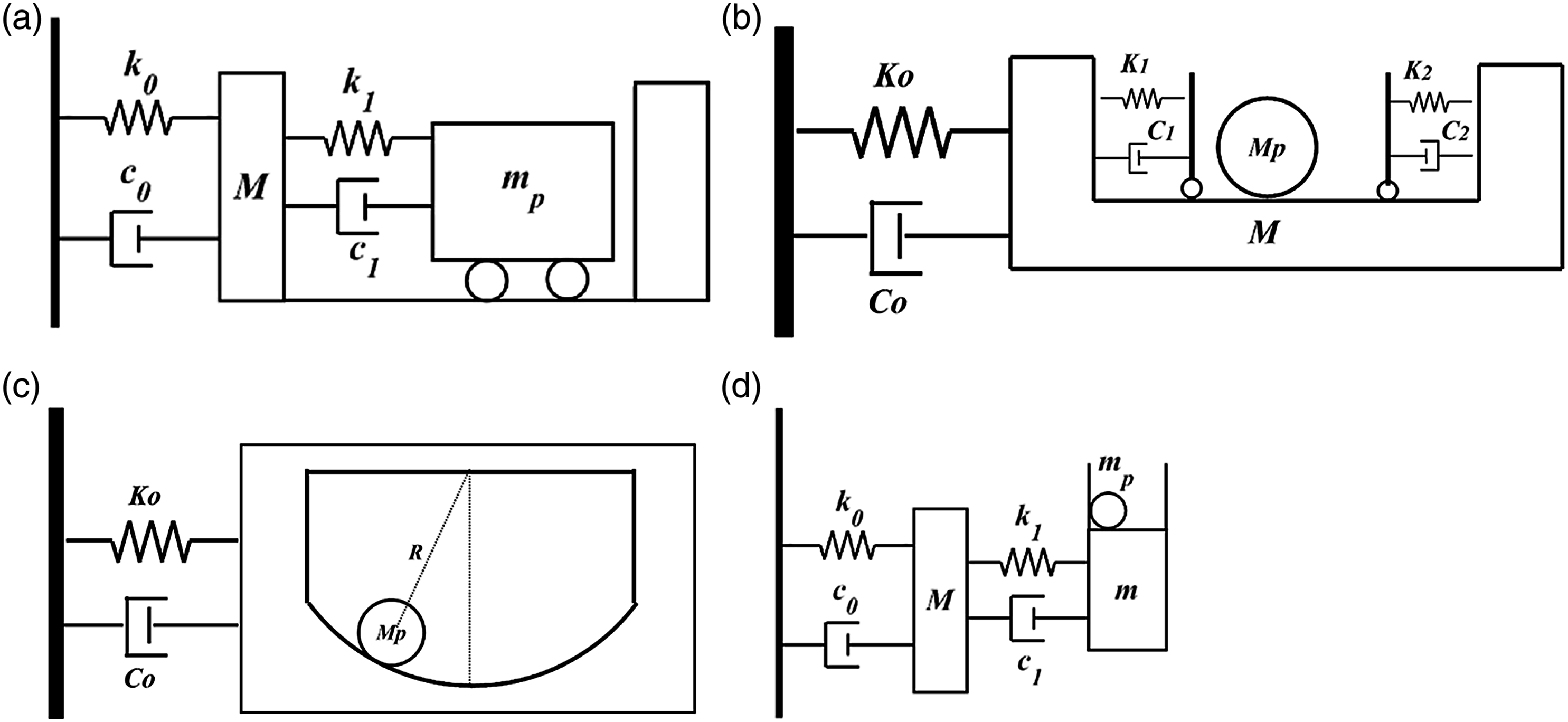
In Figure 4, M, K0, and C0 represent the mass, stiffness, and damping of the primary structure, repectively; m, k 1 , and c 1 represent the stiffness and damping of the attached TMD system, respectively; m and m p represent the mass of the secondary system and the impact mass, respectively.
2.5.4. TMD design based on coupled DOF
The original MDOF-TMD system presented by Zuo and Nayfeh (2004) has been introduced in Section 2.4. Zuo and Slotine (2005) and Zuo and Nayfeh (2006) have also extended the MDOF-TMD design to the main structures with both rotary and displacement degree of freedoms, as shown in Figure 5(a). The DTMD design for the main structures with both rotary and displacement degree of freedoms, as illustrated in Figure 5(b), has been investigated by Jangid and Datta (1997), Lin et al. (1999), Arfiadi and Hadi (2000), Singh et al. (2002), Pansare and Jangid (2003), Lin et al. (2005), Wang and Lin (2005), and Li and Qu (2006). One can also utilize the composite and distributed TMD designs illustrated in Figures 1(b) and (c), respectively, and integrate them with the main system as shown in Figures 5(b) and (c) to suppress the translational and rotary vibration of the main structure. Here, it should be noted that the key point for this kind of design is to select suitable objective function for the design optimization procedure. It should be noted that these TMD configurations allow attenuation of both translational and rotary vibrations of the main primary system at the same time, rather than designing an individual TMD system to control translational and rotary motions separately. This can significantly reduce the mass of TMD systems. Modified TMD design for main structures with both rotary and displacement DOF. (a) MDOF-TMD design; (b) DTMD design; (c) composite TMD design. Note: DOF, degree-of-freedoms; MDOF, multiple degree-of-freedoms; TMD: tuned mass damper.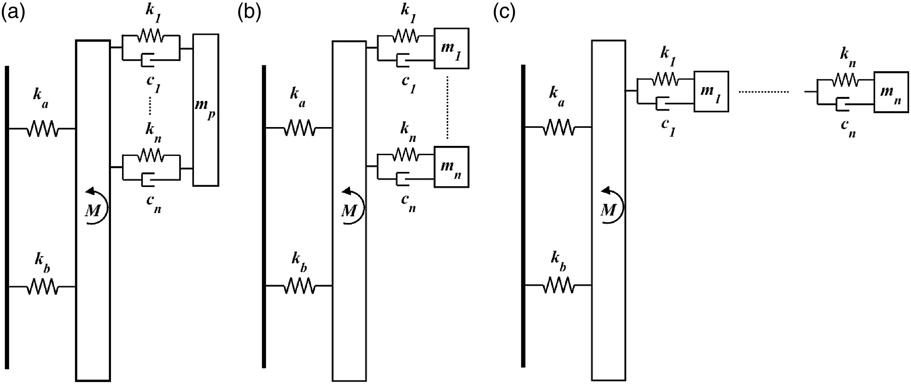
In Figure 5, M, k a , and k b are the mass and stiffness of the primary structure. Other definitions are similar to those defined in Figure 1.
In this section, the basic TMD design concept and its main modifications have been introduced. To obtain the best vibration suppression performance, the next step (Section 3) is to obtain the related numerical model and then to select the optimization procedure (Section 4) based on the established model.
3. TMD in discrete and continous structures
This section will be mainly focused on the modeling procedure for discrete and continuous structures with the attached TMD systems.
3.1. Discrete main structures
In Figure 1(a), let us define parameters M and m, K and k, and C and c to represent the mass, stiffness, and linear damping of the primary structure and the attached TMD system, respectively; x and F represent the magnitude of the main structural response and the excitation force applied to the main structures, respectively; y represents the response of the attached TMD. Obviously, the damped SDOF system with TMD, as shown in Figure 1(a), is a simple two DOF combined system, and the equations of motion can be obtained as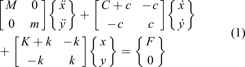
This is the mathematical model for the simplest TMD design. Based on equation (1), many optimization design methodologies have been developed for the TMD system integrated with SDOF structures to suppress the structural vibration induced by various types of excitation sources such as harmonic and random excitations. It should be noted that for the TMD modifications, as illustrated in Figure 1, the modeling procedure is similar to conventional TMD system. The governing equations of motion for these variants of TMD attached with primary system can be easily derived and represented similar to that of equation (1) following the standard modeling procedure (Den Hartog, 1956).
It is noted that for discrete MDOF models, such as those representing skyscrapers and buildings, with the attached TMD systems, the governing equations can also be represented similar to that in equation (1) except that mass, damping, and stiffness of the main structural system (M, C, and K) should be represented by the respective matrices to model the MDOF system.
Previous introductions are mainly related to attaching TMD or its modifications onto a structure modeled as SDOF or discrete MDOF systems. It is noted the procedure used to model the primary SDOF and MDOF systems with integrated TMD systems is similar. Here, it should be noted that for the discrete MDOF main structure, one should consider the design of TMD based on the targeted vibration mode to be suppressed. The modeling procedure will then be focused on this design mode. After obtaining the model (equations of motion), the main differences in this area are typically the adopted optimization methodologies, which will be discussed in detail in Section 4.
3.2. Continuous main structures
TMD technology has also been utilized to suppress the vibration of continuous structures. The main objective here is to suppress the vibration response utilizing single TMD (fundamental mode) or MTMD systems (several primary vibration modes). Based on the introduction presented by Jacquot (1978), the first work about beam-type structures with the attached TMD system was presented by Young (1952). Snowdon (1966) investigated the vibration suppression of beams with different boundary conditions using TMD. Warburton and Ayorinde (1980) utilized Den Hartog’s method (Den Hartog, 1956) to investigate the vibration suppression for plate- and shell-type structures using TMD.
Jacquot (1978) and Yamaguchi (1985) investigated a cantilever beam with mid-span attached TMD system. They both investigated the effectiveness of the dynamic vibration absorber attached to the midpoint of the beam under sinusoidal base force excitations, respectively, and presented the values of optimum tuning design parameters to suppress vibration based on the fundamental mode.
Manikanahally and Crocker (1991) reported procedures to design TMDs to suppress vibration of a general mass-loaded beam system at frequencies which they are tuned to operate. Gu and Xiang (1992) and Gu et al. (1994) considered a long-span bridge, with the attached TMD subjected to wind loadings. Esmailzadeh and Jalili (1998) investigated a cantilever structurally damped Timoshenko beam with attached TMDs in the mid-span. They presented a procedure to optimally design dynamic vibration absorbers based on the number of significant vibration mode to be suppressed. Andersen et al. (2001) considered vortex-induced loads on slender one-dimensional structures with TMD. Jensen (2002) investigated the optimal TMD system for the cable-stayed bridges to suppress the cable vibration. Chen and Cai (2004) studied a long-span bridge structure with the attached TMD.
Younesian et al. (2006) studied the Timoshenko beam with the attached TMD system subjected to random excitations with peaked PSD. Wu and Cai (2007) designed the TMD system, and also, the TMD with the MR damper to suppress the vibration of a taut cable. Hoang et al. (2008) examined the effectiveness of TMD system for bridge-type structures. The vibration suppression for plate-type structures using TMD can be found in the works presented by Warburton and Ayorinde (1980), Wang and Wang (1985), Wan and Wang (1988), and Cheung and Wong (2009).
The DTMD design has also been introduced to the beam-type structures. Kareem and Gu and Xiang (1992) presented a 2-DOF TMD system (DTMD) for bridge-type structures. Kareem and Kline (1995) examined the effectiveness of DTMD system for vibration suppression of structures modeled as the SDOF system. Similar problems have also been studied by Chang and Chang (1998), Gu et al. (1998), Wu and Whittaker (1999), Wu (2004), and Lin et al. (2000, 2005), in which the DTMD concept has been utilized to suppress the vibration of continuous structures, modeled as a SDOF system.
Das and Dey (1992) investigated the single TMD and DTMD for truss- and beam-type structures. Gu et al. (2001) investigated vibration suppression of bridges using DTMD. Wu (2003) extended the study (Wu, 2004) to a nonuniform cantilever beam, which was modeled as a step beam, with DTMD. Kwon and Park (2004) presented the DTMD design for bridges based on the fundamental torsional mode. Chen and Huang (2004) presented the TMD and DTMD design for Timoshenko beam utilizing Den Hartog’s method (Den Hartog, 1956), and their studies are also focused on the first vibration mode.
The other type of extension of TMD or DTMD design for beam-type structures is for beams subjected to moving loads. This kind of problem has been investigated by Kwon et al. (1998), Jo et al. (2001), Wang et al. (2003), Yau and Yang (2004a, 2004b), Chen and Chen (2004), Lin et al. (2000), and Chen and Wu (2008).
One can utilize different classifications to categorize the research articles regarding the TMD system for continuous structures, such as the modeling procedure, loading condition, the structure itself, and the adopted optimization methodologies. This section will be mainly focused on the modeling procedure, as it is the most essential step for the TMD design for different kinds of continuous structures. For the modeling procedure of the continuous type of structures with TMD, there are basically three approaches described in the following subsections.
3.2.1. Design based on the dominant vibration mode
In this case, the design is focused on dominant vibration mode of the main structures. The TMD is assumed to be directly connected to the dominant mode, and then the modal mass, stiffness, and damper of the TMD system are obtained. Therefore, this kind of design is similar to that for SDOF main structure, as presented in Section 3.1. The general approach to establish the equations of motion is typically simplifying the equations of motion to a SDOF system based on the modal shape (generated coordinate systems and eigenfunctions) of the continuous system. Therefore, the design can be focused on one special mode (normally first mode). This methodology has been adopted by almost all of the researchers in the previous works, addressing the TMD system for continuous structures, as discussed in Section 3.2.
In previous studies, addressing beam-type structures with attached TMD or DTMD systems, most researchers focused on the first vibration mode. As mentioned by Chen and Huang (2004) that “In most cases the fundamental mode or the first important mode of the beam is probably the most important one which should be taken into account in the design of TMDs.” However, if the multiple vibration modes are to be considered, the MTMD design should be considered. This is the topic of Section 3.3.
3.2.2. MDOF main structures
In this case, the continuous structures are modeled as a MDOF main structure, and then the whole design would be the same as those presented in Section 3.1. Wirsching and Yao (1973) first investigated the buildings with single TMD installed on the top floor subjected to wind loadings, and the studies were mainly focused on the first vibration mode. Later, Wirsching and Campbell (1973) calculated the optimal TMD parameters for different building models subjected to stationary white noise base acceleration. Kawaguchi et al. (1992) investigated the response of building structures with TMD under gust wind.
Xu et al. (1992) presented an investigation of TMD and tuned liquid column damper (TLCD) for tall/slender structures modeled as discrete MDOF system. Loh and Chao (1996) examined a three-floor building model with top floor installed TMD under random loadings. Rana and Soong (1998) also studied the discrete MDOF structures with TMD, and extended the work to MTMD, in which TMDs were tuned to different modes of the primary structures.
Hadi and Arfiadi (1998) presented the investigation of an N-story shear building with top floor installed TMD. Cao et al. (1998) examined the vibration suppression of a tall TV tower using TMD and active mass damper. Similar problems (TMD design for building-type structures modeled as MDOF) have also been investigated by Ricciardelli et al. (2000), Wang and Fung (2001), Lin et al. (2005), Ozer and Royston (2005), Hwang et al. (2006), and Marano et al. (2007). Liu et al. (2008) investigated the vibration suppression of high-rise building considering the soil–structure interaction. The experimental investigation for TMD installed in slender tower or building-type structures can be found in Tanaka and Mak (1983), Xu et al. (1992), and Gerges and Vickery (2003a, 2003b).
3.2.3. Combining continuous structures with the attached TMD
In this case, the governing differential equations of motion for continuous structures with attached TMDs are directly obtained. The Lagrangian or extended Hamilton’s principles are generally utilized to derive the coupled governing equations of motion. One may utilize the eigenvector (eigenfunction) of the original continuous system to separate the design mode(s) of the combined system. For different continuous structures, the whole modeling procedure for this kind of problem is similar, and thus, this study will be mainly focused on the modeling procedure for beam-type structures with TMD. Manikanahally and Crocker (1991) and Esmailzadeh and Jalili (1998) adopted the mode expansion and Lagrange’s equations to derive the equations of motion for a cantilever beam with attached TMD system, and then obtained the expression of the transverse deflection at any location on the beam. However, the above methodologies have some restrictions such as (1) the modal shapes of the continuous system will change with different boundary condition, thus one should repeat the whole procedure for different boundary conditions; (2) it is difficult to obtain the modal shapes for the nonuniform structure and also the curved beam structure; (3) it is very difficult to directly solve the differential equations of motion, especially for nonuniform beams.
Here, it should be noted that one significant difference between the TMD design for discrete and continuous main structures is the location of the TMD system in the continuous main structures, which should be predefined or obtained through an optimization procedure. Although, the position of TMD has been expressed as a variable in the established equations of motion (Esmailzadeh and Jalili, 1998; Manikanahally and Crocker, 1991; Rice, 1993), it has been assumed as a given input in the design optimization procedure. For instance, in the article presented by Rice (1993), the initial positions for the two absorbers were intuitively selected at 0.5 and 0.75 of the beam length, “where the mode shapes are close to their maxima.”
Considering above, one can realize that it is necessary to establish a general design approach for optimal TMD related to the continuous structures, which can not only provide a simple and straightforward solution approach but also involve the number and location of the attached TMD as the design variables. Therefore, in the next section, the modeling procedure for the TMD (MTMD) design for continuous structures, which should consider the combination of the continuous structures with the TMD together, will be presented.
3.3. Position of TMD(S) for continuous main structures
Most of research articles regarding the beam type structures with the attached TMDs are focused on the cantilever beams or beams with symmetrical boundary and geometric conditions, and then considered the first vibration mode, which generally is the dominant vibration mode. Obviously, in these cases, the position of the TMD is at the end or the mid-span. Rice (1993) designed a MTMD system to suppress the vibration of a cantilever beam’s first two modes. Larose et al. (1995a, 1995b) tested the effectiveness of TMD and MTMD design on a full-bridge aeroelastic model.
Manikanahally and Crocker (1991) considered a mass load cantilever beam with tip-attached MTMD, which was utilized to suppress the vibration related to the first two modes. Das and Dey (1992) extend their study to optimal MTMD design based on beam- and truss-type structures’ first two vibration modes. Esmailzadeh and Jalili (1998) also presented MTMD design for a cantilever beam, in which two TMDs were attached to end of the beam and utilized to suppress the vibration due to the beam’s first two modes.
However, for beams with multiple dominant vibration modes or unsymmetry boundary and/or geometric conditions, the position(s) of the attached TMD(s) should be considered in the design optimization procedure. Generally, based on the working principle of the TMDs, their locations are close to the antinodes of the modes on which they are TMD (Fitzpatrick et al., 2001). However, it should be noted that “close” is quite a vague definition for the optimal TMD system.
To obtain the best vibration suppression performance, especially for the main continuous structures with multiple dominant vibration modes or antinodes, it is necessary to establish an optimal procedure to evaluate the optimum values of the location, numbers, and parameters of the TMD system efficiently, and/or to verify the validity of directly installing the TMD at the close position of each antinodes.
As mentioned before, in some research works, while the position of TMDs has been expressed as a variable in the established equations of motion (Esmailzadeh and Jalili, 1998; Manikanahally and Crocker, 1991; Rice, 1993), it has been then assumed as a given input in the design optimization procedure. Recently, Zuo and Nayfeh (2005) and Wong et al. (2007) investigated an Euler beam with attached TMD system using FE method, in which the location of the TMD was restricted to the node of FE model. However, it is still difficult to register the position of the attached TMD system as one of the design variables.
Considering the above, Yang et al. (2009a) developed a FE approach to study the vibration suppression of Timoshenko beam with attached TMD system, and then they extended the study to curved beam-type structures (Yang et al., 2009b) in which the position of TMD can be located in any place along the beam. Therefore, the position of the attached TMD can be enrolled in the design optimization procedure. To investigate the optimum location of the MTMD system to the continuous structures with multiple dominant modes (MTMD design), Yang et al. (2014) also established a hybrid optimization procedure (combined genetic- and gradient-based algorithms) to accurately catch the global optimal location of the attached TMD system in the beam-type structures, and then summarized a general step-by-step design procedure of the TMD/MTMD system for continuous type structures.
4. Optimally designed TMD system
Although the basic design concept of a TMD system is quite simple, its parameters (damping and stiffness) must be determined through an optimal design procedure to attain the best vibration suppression performance. Therefore, the major task is to obtain the optimal design parameters of the TMD system to enhance its vibration suppression effectiveness. Because Den Hartog (1956) first proposed an optimal design approach of TMD for an undamped single-degree-of-freedom (SDOF) structure, many optimal design methods of TMD system have been developed to suppress the structural vibration induced by various types of excitation sources. Crandall and Mark (1963) adopted the random vibration theory to analyze a SDOF structure attached with a single TMD system under white noise base excitation.
The results demonstrated that the TMD system can effectively reduce the vibration of the base-excited structure. Warburton and Ayorinde (1980) studied SDOF system vibration suppression using TMD under different loading conditions utilizing Den Hartog’s method, and then extended the study to plate- and shell-type structures. Thompson (1981) investigated the optimal TMD for a damped primary system under force excitation. Warburton (1982) summarized the optimal TMD design for SDOF structures under different excitation conditions. Vickery et al. (1983), Xu and Kwok (1994), and Kwok and Samali (1995) studied the effectiveness of the TMD system for the building structures, which were modeled as SDOF structures, subjected to wind loadings.
The topic for vibration suppression of a SDOF system using the attached optimal TMD system has been extensively studied in which the TMD’s optimal parameters for different excitation conditions have been obtained. Here, some earlier sample and recent published works would be presented. Rana and Soong (1998) conducted a systematic parametric study to investigate the effect of TMD’s parameters and their detuning on the vibration suppression performance of the TMD. They also presented a simplified TMD design based on the design of the TMD for the SDOF structure to attenuate a single mode of a MDOF structure. Chang (1993) utilized the methodology provided by Crandall and Mark (1963) to investigate the optimal TMD and TLCD design under random excitation.
Tsai and Lin (1993) studied the optimal TMD system for damped primary structures subjected to harmonic base excitations. Asami et al. (2002) utilized the H∞ and H2 optimization methods to investigate the optimal TMD design for SDOF structure, and compared their results with those obtained analytically or numerically. Marano et al. (2008) presented the optimal TMD design for SDOF structure with random properties for both TMD and primary structures. Leung and Zhang (2009) provided the explicit expressions of the optimum TMD’s parameters.
The main differences in these articles include (1) the selected optimization criteria, such as the variance or root mean square (RMS) of the response and the magnification of transfer function or the dynamic magnitude factor (DMF); (2) the methodologies utilized to solve the established equations of motion based on the selected objective functions; and (3) the adopted optimization methodologies. Here, it should be noted that there are enormous number of research articles which have utilized different solution and optimization strategies to solve the governing equations of motion to identify TMD’s optimal parameters. Addressing all these articles would not be possible, thus this section will be mainly focused on the statement of the typical design optimization problem of TMD system and the selected optimization methodologies.
4.1. Optimization problem
Selecting a suitable objective function with appropriate design constrains are of the paramount importance for the successful implementation of an optimization problem. For random-type loadings, the objective function can be selected as the variance of response. For stationary random loading, the power spectral density (PSD) function of structural response can be expressed as (Wirsching, 1995)
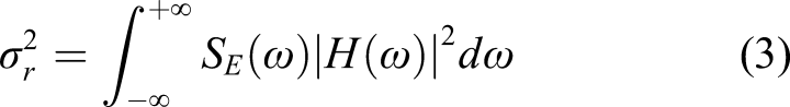
This methodology has been adopted by many researchers (Rana and Soong, 1998; Sun et al., 1995). For SDOF or discrete MDOF systems with TMD problem, one can also utilize some available experimental function to obtain the value of the objective function.
For continuous type structures, Manikanahally and Crocker (1991) and Esmailzadeh and Jalili (1998) minimized the beam dynamic response as objective function over a broad frequency range, which was obtained by transferring the time domain of beam response to the frequency domain expression using the infinite Fourier’s integral transform. Yang et al. (2009a, 2009b, 2014) selected the random vibration matrix analysis method (Lutes and Sarkani, 2004) to find the variance of structural response. The basic idea of the random vibration matrix analysis method is to transfer the equations of motion to the following state-space form, which is a first-order differential equation as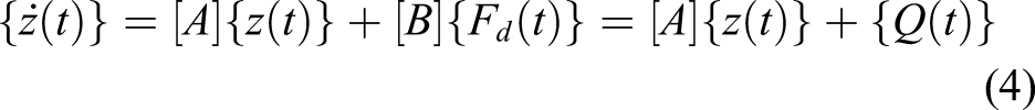
Under stationary random loading, knowing the PSD function of external excitation [S
QQ
(ω)], the PSD of state-space vector can be obtained as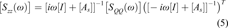

This methodology allows one to attain the response at any point of continuous structures considering the effect of higher vibration modes.
Here, it should be noted that the norm of the transfer function (H2 or H∞ norms) has also been selected as the objective by many researchers, such as the articles presented by Hadi and Arfiadi (1998), Asami et al. (2002), and Cheung and Wong (2009). For random type loading, the selected objectives (variance or norm) are quite clear, and most researchers utilized these definitions.
However, there are generally no unique optimization criteria for harmonic excitations. Den Hartog (1956) proposed a methodology to solve the optimal TMD parameters integrated with a SDOF system under harmonic loading, which was widely accepted by research community. As this is the first reported optimization methodology to identify the optimal parameters of the TMD system, a short discussion of this method will be presented. Because the design variables of a TMD system include the coefficients of damping and stiffness for a known input mass, Den Hartog (1956) had separated these two design variables in the first step. Let us consider a SDOF structure, subjected to a harmonic-type base excitation. The related magnitude of the transfer function can be expressed as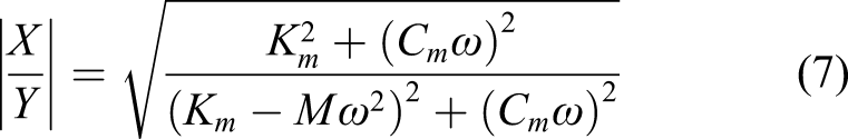
This type of transfer function has an important property, in which the value of the magnitude is independent of the damping, when the excitation frequency becomes equal to 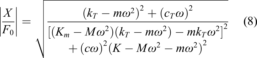
In this case, the damping of the main system has beam ignored. X and F0 are the respective response of the system and the external force excitation, applied on the main structures. The parameters 
4.2. Optimization method
Optimization methodology is another important issue for an optimal design problem. Generally, the optimization methodologies adopted in the optimally designed TMD system can be classified into three main categories: (i) Den Hartog’s methodology, which has been introduced in detailed in the last subsection; (ii) the gradient based optimization method; and (iii) the global optimization methodologies.
The gradient-based optimization methodology plays an important role in the TMD design area. The simplest one can be seen in the work of Den Hartog (1956), in which the optimal damping (c) was obtained directly utilizing the first-order (gradient function) and the second-order (Hessian matrix) criteria, which are known as the Karush–Kuhn–Tucker (KKT) conditions [145] without constraints. Zuo and Nayfeh (2005), Lee et al. (2006), and Li and Zhu (2006) utilized the steepest decent algorithm method to solve their TMD optimization formulation. Hoang and Warnitchai (2005) derived the gradient matrix of the objective function and then utilized the Davidon–Fletcher–Powell algorithm (Rao, 1996) to attain the optimum solution. Sequential quadratic programming is the most recently developed and perhaps one of the best and most powerful methods to solve constrained nonlinear optimization problems (Rao, 1996). Recently, many researchers have utilized this method to obtain the optimal TMD design. While gradient-based optimization methods can accurately capture local optimum points, they generally have no mechanism to search for the global optimum points.
To address this limitation, the global optimization methods, especially stochastic-based optimization algorithms have also been utilized to find the optimum design parameters of the TMD system. Hadi and Arfiadi (1998) used the genetic algorithm (GA) and Febbo and Vera (2008) utilized the simulated annealing (SA). Here, it should be noted that other numerical searching methodologies are also available in published articles, such as the work conducted by Park and Reed (2001) who presented a searching algorithm to attain the optimal DTMD design. As the introduction of GA, SA, and numerical searching method is out of the scope of this study, for more detailed information about GA, SA, and numerical searching algorithm, one can consult the books and article by Haupt and Haupt (2004) and Aarts and Korst (1989).
4.3. Optimization based on the control loop
From the point of control theory, to find the optimal coefficients of stiffness and damping of the TMD system is equivalent of finding the optimal PD controller with the boundaries as the positive values. Therefore, one can apply the PD controller design methodologies to the TMD design, such as the work presented by Riganti and Zavattaro (1994) and Carotti and Turci (1999). Here, the optimal DTMD methodology proposed by Zuo and Nayfeh (2004) will be selected to illustrate the basic procedure.
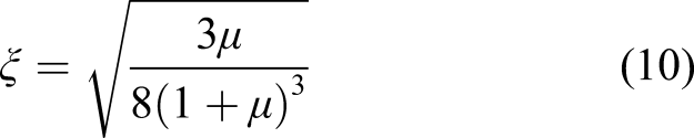
A main structure with the attached TMD(s) system can be expressed as the linear fractional transformation format as shown in Figure 6: The matrices A, B1, B2, C1, C2, D11, D12, D21, and D22 in Figure 6 correspond to the primary system, whereas {w},{y},{z}, and {f} represent the external excitation, output signal, measured, and the “control” force vectors, respectively. Parameters k and c represent the stiffness and damping of the designed DTMD system, respectively, with the predefined form (positive values). The transfer function including its norm can be easily obtained through available numerical methodologies (Zhou, et al., 1996) and hence, the optimization objective is to find the values of k and c to minimize the norm of transfer function between {w} and {y}. The LFT diagram for a structure with the DTMD design. Note: LFT, linear fractional transformation; DTMD, distributed tuned mass damper.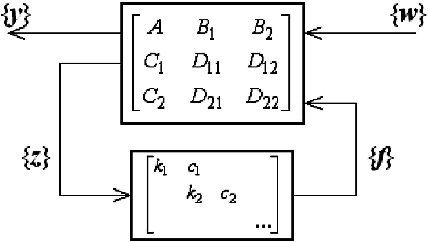
Recently, utilizing the control methodologies to design the TMD system has become one of the main topics in the TMD design area. Zuo and Slotine (2005) used the frequency shaper slide control and modal decomposition methodology to design two DOF-TMD systems. Bisegna and Giovanni (2012) utilized the pole base design method to derive a closed-form formula for the class TMD design. Roffel and Narasimhan (2014) applied the Kalman filter technology to design a pendulum tuned mass damper. Bozer and Altay (2013) selected the hybrid tracing controller design methodology.
4.4. Optimization for DTMD systems
The basic design concept and methodologies for the DTMD system has been presented in Section 2.3. The traditional design approach of either TMD(s) or DTMD is to find the optimal stiffness and damping factors with the predefined mass(es). Yang et al. (2015) proposed a novel design approach, in which, the design is concentrated on the attached masses with the given values of stiffness(es) and damper(s). This methodology could provide a much simple and more cost-efficient approach in manufacturing, installation, and maintenance than the traditional one. Moreover, based on the results illustrated by Yang et al. (2015), as illustrated in Figure 7, when comparing with the conventional design, the DTMD design is focused on the masses that can provide better robust properties, under the same (close) total mass of the secondary system. SDOF main structural frequency response comparisons. Uncontrolled structure (solid line); structure with optimal single TMD (dashed); structure with optimal DTMD based on mass distribution (dashed-dotted); structure with optimal DTMD based on classical design approach, Section 2 (dotted lines) Yang et al. (2015). Note: Single degree-of-freedom; TMD, tuned mass damper; DTMD: distributed tuned mass damper.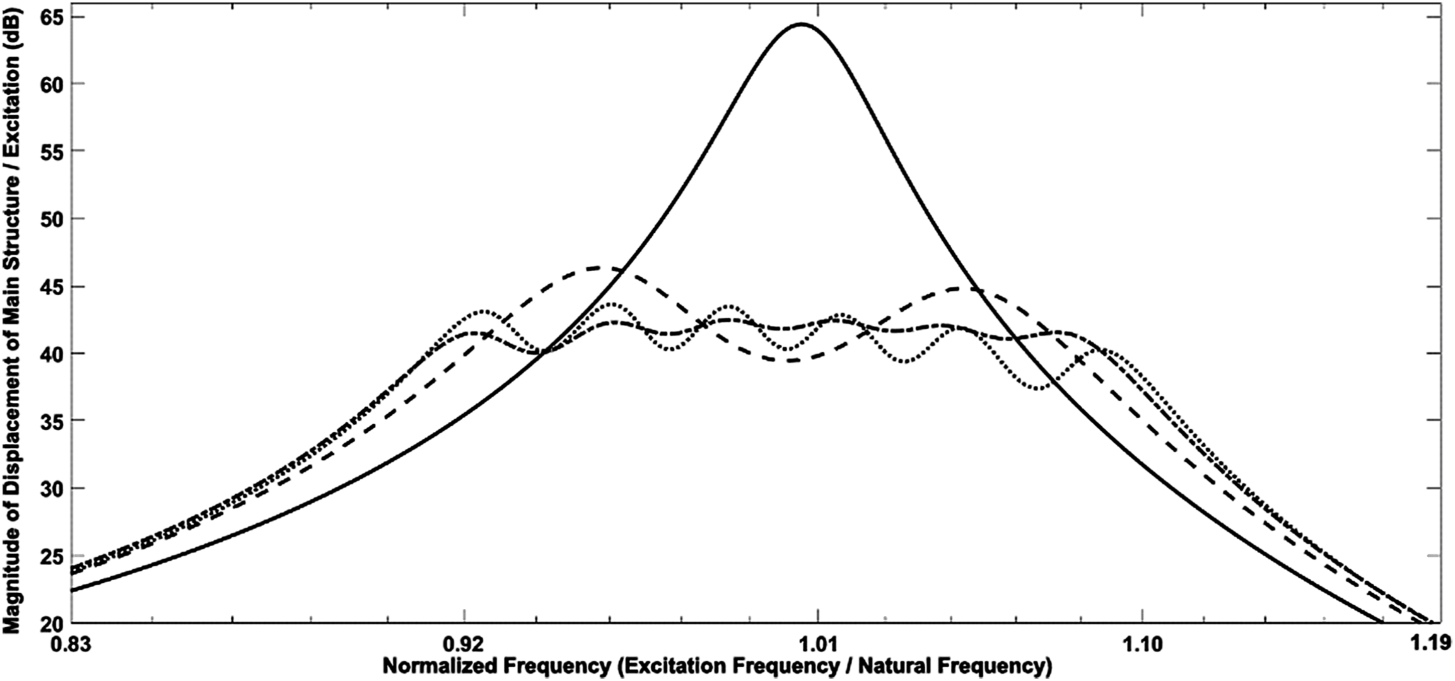
It should be noted that under the same conditions and optimization procedure, the performance of the attached TMD system will be increased with the increase of the total mass of the attached secondary system. It is, however, noted that generally the total mass of the attached secondary system should not exceed 10% of the mass of the main system (Warburton, 1982). Comparison of the performance of different TMD designs for the same secondary and primary masses generally is not possible. For example, in CTMD design shown in Figure 1(b) for the same secondary mass as that of single TMD shown in Figure 1(a), different distribution of secondary masses 1 and 2 would result in different system response. As there are virtually infinite combination for selection of masses 1 and 2 in CTMD design, it is not possible to have fair one-to-one compassion between different designs.
It should also be noted that generally deferent objective functions based on the practical requirement and excitation conditions may be selected for formulation of optimization problem. For example, for random excitation, it is not suitable to utilize the methodologies developed for the harmonic excitation. Even for random excitation, one can select different objective functions such as H2 norm, maximum PDF, and H-infinity. Therefore, it is difficult to evaluate the performance using the same standard for TMD designs based on different objective functions.
4.5. Optimization parameter analysis of different TMD systems
It is quite well-known that TMD design is based on practical applications, which includes the main structure and its typical loading condition. Thus, it should be noted that the performance of the TMD system should be evaluated case by case. In the following, the performance evaluation of TMDs, considering different design objectives, the mass ratios, and different types of TMDs is discussed.
4.5.1. Design objectives
Den Hartog (1956) introduced the min–max optimization for SDOF main structures (without damping) with the TMD subjected to harmonic loading. Crandall and Mark (1963) presented the SDOF main structures (without damping) with the TMD subjected to random excitation. Warburton (1982) has shown that although the optimum results were obtained, based on the harmonic loading and random excitation, are close, but it is optimum only for the related design objective. It is quite easy to understand that the optimum results obtained, based on one optimization procedure, will not be the optimum for another optimization procedure.
Even for the random excitation, one can select different objective functions, such as the H2 norm, maximum PDF, and the H-inf (Zuo and Nayfeh, 2004). Therefore, it is very difficult to evaluate the performances using the same standard for different types of TMD design based on different objectives. Here, Figure 8 illustrates the vibration suppression performance of a MDOF-TMD design, as shown in Figure 5(a), based on different design objectives, and it is evaluated based on the displacement of main structures (Zuo and Nayfeh, 2004). As it can be realized, the results are considerably different for the MDOF-TMD design based on different design objectives. From the point of optimization theory, it may not be appropriate to design the system based only on one objective function and cannot compare it with the performance based on another objective function. MDOF main structural frequency response comparisons (design based on MDOF-TMD, as illustrated in Figure 5(a)) (Zuo and Nayfeh, 2004). Uncontrolled structure (dotted line); structure with optimal MDOF-TMD design based on H2 optimal (solid line); structure with optimal MDOF-TMD design based on H-inf optimal (dashed line); and structure with optimal MDOF-TMD design based on min-max design (dashed-dotted line). Note: MDOF: multiple degree-of-freedom; TMD: tuned mass damper.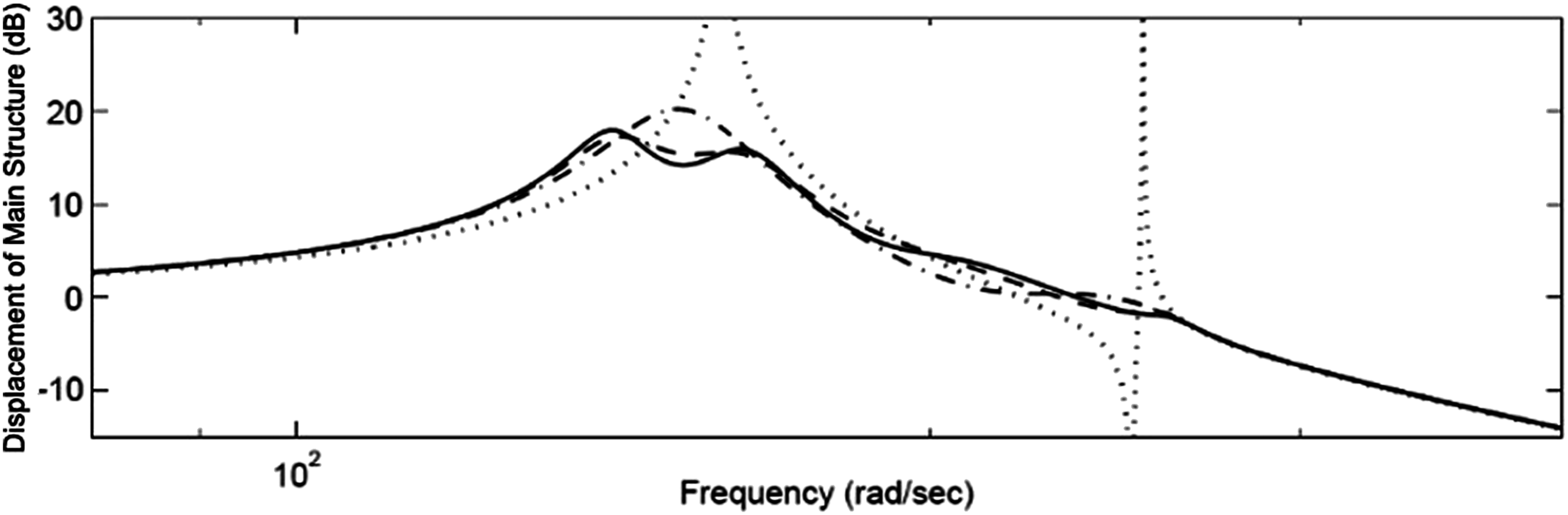
4.5.2. The effect of mass ratio
It is well-known that (1) under the same optimization procedure, the performance of the TMD system is increased with the increase of the total mass of the attached TMDs; and (2) normally, the total mass of the attached TMD system should not exceed 10% of the mass of the main system (Warburton, 1982). Therefore, the effect of the secondary system will have a significant impact on the performance of the main system as violating the effect of the TMD tuned vibration absorber. Figure 9 illustrates the effectiveness of the mass ratio for the DTMD design. Similar behavior could be observed for other types of TMD design. Structural frequency response comparisons (proposed design approach). Structure with optimal DTMD design with five small TMDs under initial total mass ratio equals to 1% (solid), 2% (dashed), 5% (dotted), and 10% (dashed-dotted lines). Yang et al. (2015). Note: DTMD, distributed tuned mass damper; TMD, distributed tuned mass damper.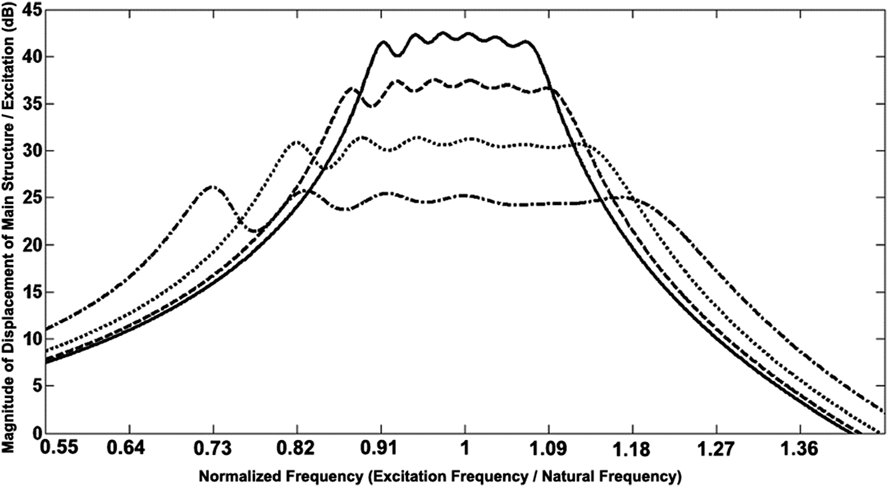
4.5.3. Effect of different types of TMD designs
Typically in the reported research studies in relation to the TMD design, the performance of the TMD systems (including any modifications) are compared with other designs, particularly the classical TMD, under the same mass ratio. Here, the CTMD, as illustrated in Figure 1(b), has been selected to present the effectiveness of the mass ratio on the CTMD design and it is compared with the classical TMD design. Figure 10 illustrates the performances of a CTMD and a classical TMD under the same total mass ratio for the sake of comparison. SDOF main structural frequency response comparisons (Design based on CTMD, as illustrated in Figure 1(b)) (Zuo, 2009). Uncontrolled structure (dotted line); structure with optimal CTMD with two TMDs and same mass (solid line); structure with classical TMD (dashed line); and optimal CTMD with two TMDs and same mass when negative damping is allowed (dashed-dotted line). Note: SDOF, Single degree-of-freedom; CTMD: composite tuned mass damper; TMD: tuned mass damper.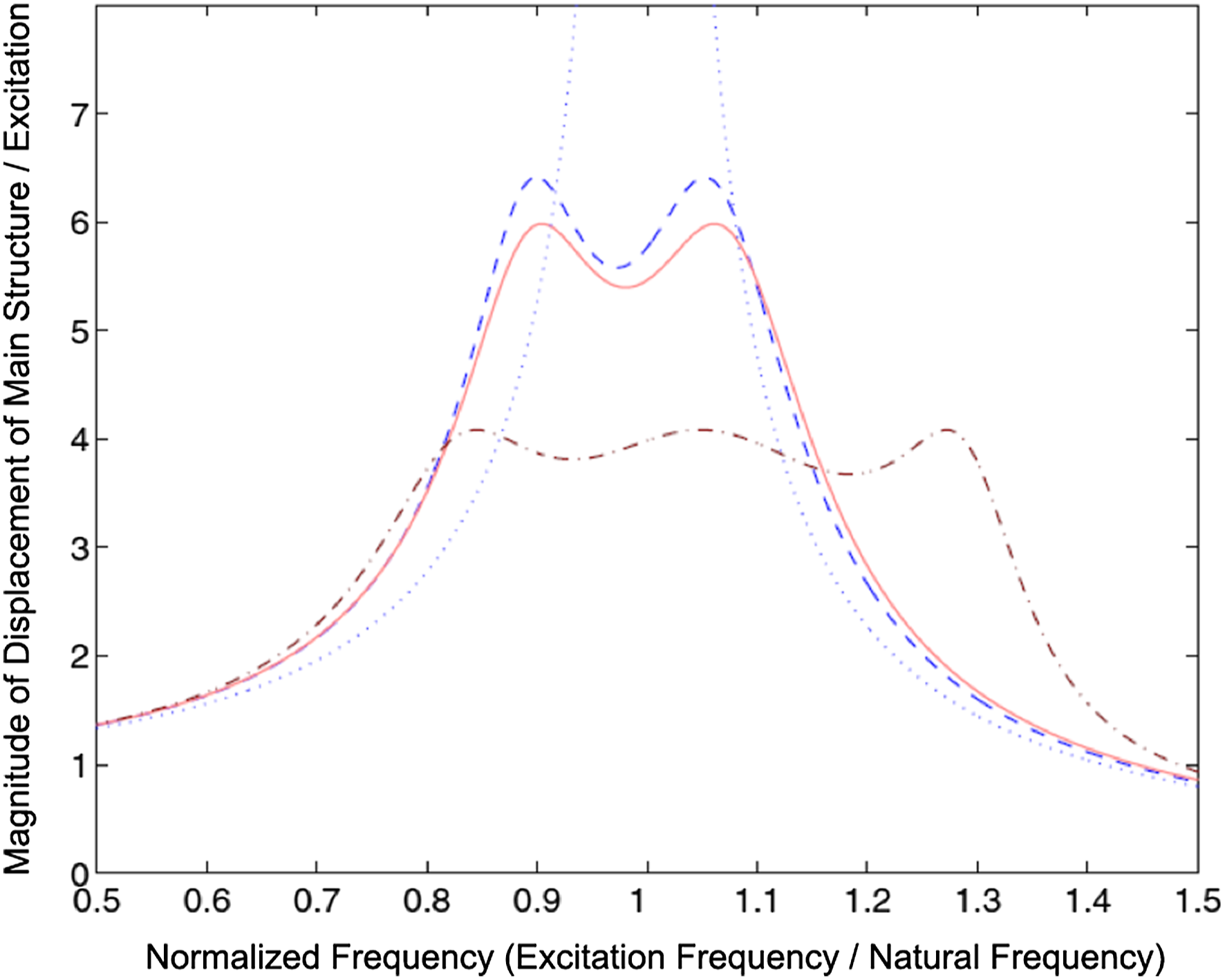
Figure 11 also compares the different TMD designs under the same total mass ratio (Zuo, 2009). As it can be observed, the CTMD design shows slightly better performance to reduce the vibration amplitude than the one with either DTMD, MDOF-TMD, or the classical TMD designs. Moreover, the vibration attenuation bandwidth is found to be substantially higher for the CTMD and DTMD designs. SDOF main structural frequency response comparisons (Zuo, 2009). Structure with optimal CTMD with two TMDs and mass distribution of 0.121 (dark solid line); structure with DTMD (dotted line); structure with MDOF-TMD (dashed-dotted line); structure with optimal CTMD with three or four TMDs (dashed line); and structure with classical TMD (light solid line). Note: SDOF, Single degree-of-freedom; MDOF, multiple degree-of-freedom; DTMD, distributed tuned mass damper; CTMD: composite tuned mass damper; TMD: tuned mass damper.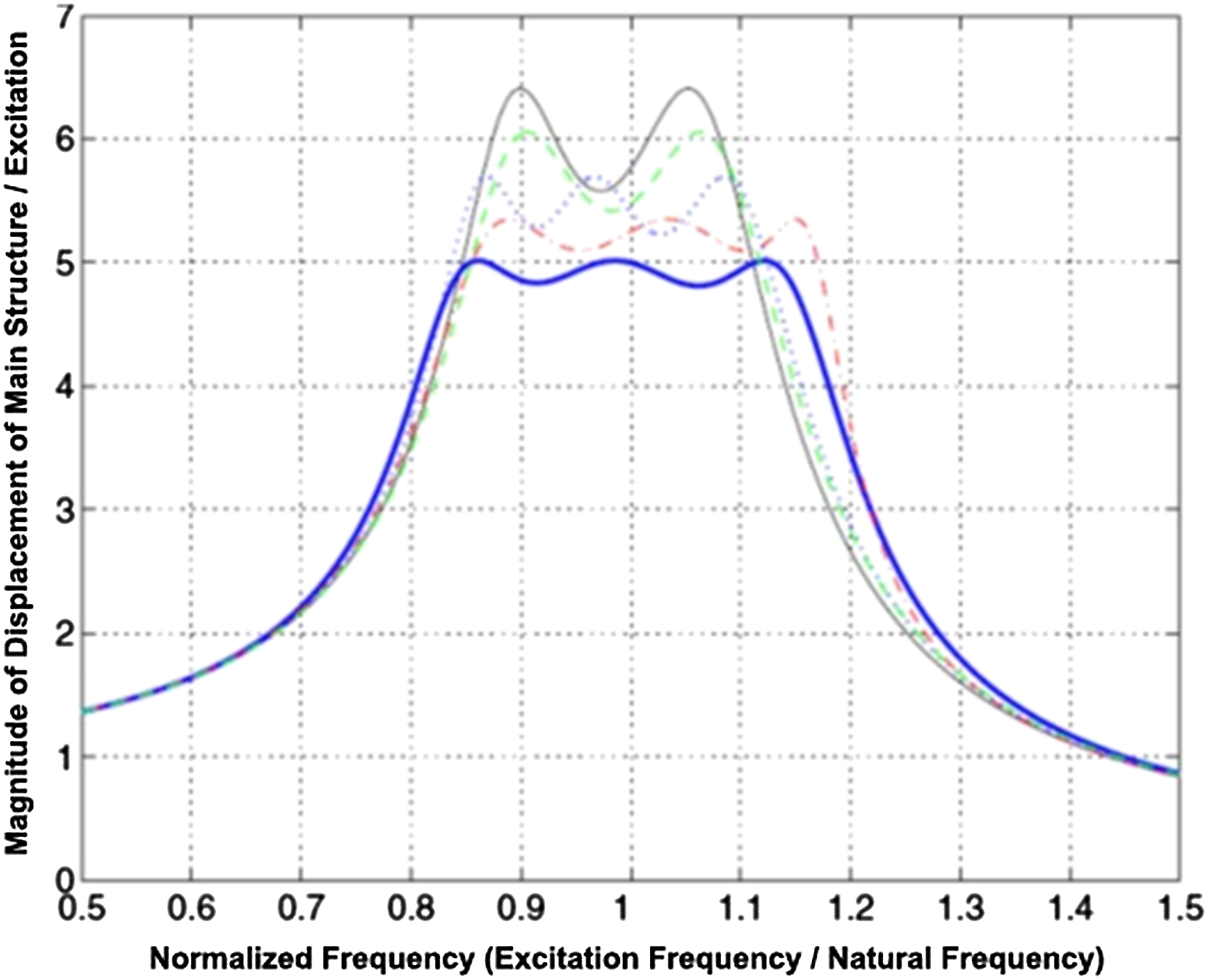
5. Recent development of TMD design
Although TMD design concept was developed decades ago, its simplicity and effectiveness have made it become one of the most popular passive vibration methods to suppress the structural vibration. It can be realized that the practical applications of TMD system are mainly in civil engineering area, such as buildings and bridges (Dupré, 1996; Fitzpatrick et al., 2001; Kwon et al., 1998; Rostam et al., 2015; Tsai, 1995). In mechanical area, the TMD system has been utilized to reduce machine components’ vibration. Liu and Rouch (1991), Rivin and Kang (1992), Tarng et al. (2000), and Sims (2007) designed a TMD system in cutting toll machine. Stefko (2002) introduced the TMD system in turbo engine’s turbine blades; Lyles (2008) and Griffin (2008) developed a TMD system to solve the potential thrust oscillation problems.
Recently, the TMD technology has been developed in different aspects. In this study, two aspects of recent development of TMD design are summarized: (1) practical realization of a TMD system; (2) practical realization of a semi-active/active TMD system.
5.1. Practical realization of the TMD system
The previous discussion regarding the TMD system is mainly focused on the modal design. Here, some important practical realization of the TMD system will be summarized.
5.1.1. Attachment of a secondary beam structure
Aida et al. (1995), Chen and Lin (1998), and Thompson (2008) introduced the double plate and/or beam structures, in which the second plate/beam was treated as a TMD system. Yang et al. (2010a, 2010b) attached a slender beam combining with two small masses, which is designed as the MTMD system, to the main structures (beams) to suppress the vibration related to the first two modes of the main structure. The key point of this kind of application is to design the secondary plate/beam or tune the vibration mode(s) of the secondary beam based on the working principle of the TMD system.
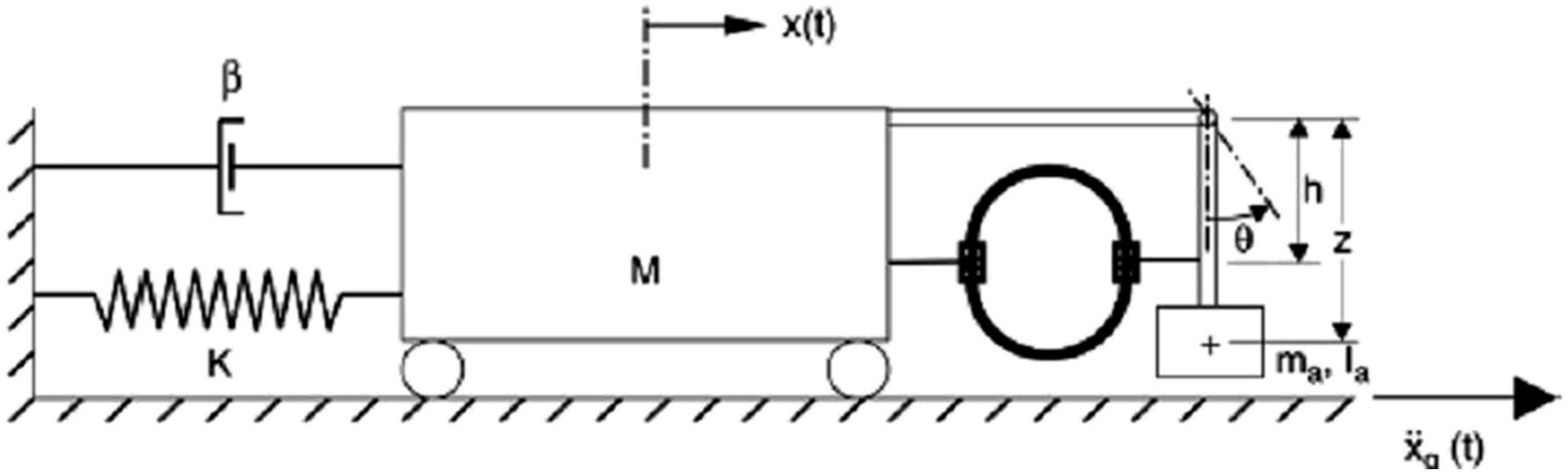
5.1.2. Ball damper or pendulum type of damper
Pirner (2002) and Fischer (2007) examined the properties of all damper, as shown in Figure 12(a), and Matta and Stefano (2009a, 200b) designed the rolling pendulum TMD system, as shown in Figure 12(b). Duffy et al. (2000) developed a self-tuning impact vibration damper for rotating turbomachinery. Gerges and Vickery (2003a, 2003b, 2005) introduced the wire rope spring pendulum TMD, as shown in Figure 13. The essential points of this design are to find the mass and the rotation radius of the ball or pendulum system. Schematic of ball damper and rolling-pendulum TMD design. (a) Ball damper [170, 171]; (b) rolling-pendulum TMDs (Matta and De Stefano, 2009a and 2009b). Note: TMD: tuned mass damper. Schematic of SDOF system with wire rope spring pendulum-type TMD (Gerges and Vickery, 2003a and 2005). Note: SDOF, single degree-of-freedom; TMD, tuned mass damper.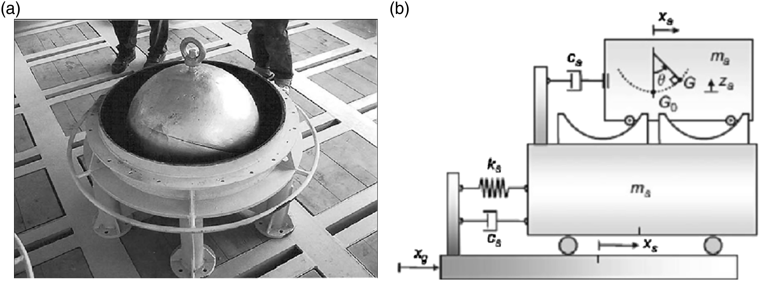
5.1.3. TLCD
The original design of TLCD, as illustrated in Figure 10 (Gao et al., 1997; Hitchcock et al., 1997a, 1997b), is a passive device and a special type of tuned liquid damper (TLD) (Sun et al., 1992), which suppresses the structural vibration through shallow liquid sloshing in a rigid tank, as illustrated in Figure 14(a). TLD and TLCD technologies have been successfully applied in many structures, and one can consult the article by Hochrainer (2005) for more information. Schematics of typical liquid damper design. (a) Traditional tuned liquid damper (TLD); (b) Tuned liquid column damper (TLCD); (c) semi-active TLCD with variable orifice; (d) semi-active TLCD with propellers; (e) semi-active TLCD using magneto-rheological fluid with adjustable magnetic field. Note: TLCD: tuned liquid column damper.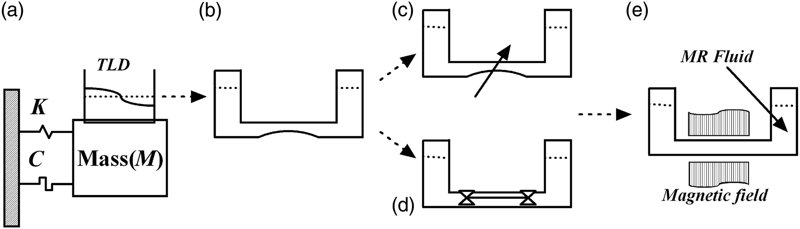
5.2. Semi-active/active TMD system
As the damping and stiffness of an optimally designed TMD system cannot be changed under different excitation conditions, the effectiveness of the TMD system is restricted to its TMD frequency. Subsequently, it provides limited vibration suppression performance for the random type excitations or excitation frequency far away from its TMD natural frequency. Considering this restriction and also to improve the effectiveness of the TMD system over a broad range of frequency, a controllable device (full-active or semi-active) will be added to or replace the damper/stiffness in the TMD system. The so-called active mass damper (AMD) or semi-active mass damper (SAMD) system is developed to improve the vibration suppression performance of the optimal TMD system. Here, it should be mentioned that some researchers also called AMD as active TMD (ATMD).
Hrovat et al. (1983) compared the performance of the passive TMD, SAMD, and AMD systems. Nishimura et al. (1992, 1998) developed the basic ATMD design method and assumed the control force generated through a simple constant acceleration feedback gain. Chang and Yang (1995) also studied ATMD design and utilized the constant displacement and velocity feedback gain to represent the control force. Olgac and Jalili (1998), Jalili and Olgac (1999), and Jalili and Knowles (2004) utilized a constant acceleration feedback to represent the control force for an active TMD system.
The AMD and/or SAMD systems can provide good vibration suppression effectiveness. However, there is a serious challenge regarding the device that can provide required control force, which should be considered before AMD/SAMD can be used practically. Dyke (1996) also summarized some other challenges such as the system reliability and robustness, reduction of capital cost and maintenance, eliminating reliance on external power, and gaining acceptance of nontraditional technology. It should be noted that without considering the dynamic properties of the practical active/semi-active devices, this kind of research is equal to a controller design with adding a virtual semi-active/active device based on equation (1). Therefore, vast number of research articles can be found in this subarea. As the number of the research articles regarding the SAMD/AMD system based on the virtual semi-active/active devices are enormous and considering the scope of this study, the focus will be on the practical realization of the AMD/SAMD system.
Here, it should be very clearly defined the so-called active and semi-active methods. From the point of energy, active method means to provide energy (force) directly to confront the vibration energy (force) of the controlled structures. Therefore, this method would not exactly match with the working principle of the TMD system. In fact, most of the research articles regarding the AMD system are actually the SAMD system, which shifts the stiffness of the attached secondary structures and/or provides controllable energy dissipation rate utilizing the controllable damper, without inducing energy to the controlled structure. Thus, the SAMD system appears to be particularly promising in addressing those challenges.
Based on the above introduction and the working principle of the TMD system, here it should be emphasized that basically there are two kinds of SAMD systems: (1) to improve the vibration suppression performance of the TMD system (design focusing on the TMD and mode of the main structures); (2) to extend the effectiveness of the TMD system to different vibration modes.
Different kinds of semi-active devices have been investigated for the SAMD system design, such as the TLCD, the variable orifice hydraulic actuator, active variable stiffness (AVS), electro-rheological (ER)/magnetorheological (MR) fluid dampers, and the magnetorheological elastomer (MRE)–tuned vibration absorbers. In the following, the commonly adopted semi-active devices mentioned above will be briefly reviewed.
5.2.1. TLCD
The original passive design of TLCD has been illustrated in Figures 14(a) and (b). In the semi-active TLCD, the aim is to adjust the damping through an added device illustrated in Figures 14(c)–(e).
Yalla et al. (2001) and Yalla and Kareem (2003) proposed an adaptive TLCD in which the size of the damper’s orifice could be adjusted to change the damping factor of TLCD, as illustrated in Figure 10(c). Chen and Ko (2003) incorporated a set of controllable propellers in TLCD and then changed the damping factor of TLCD through adjusting the rotation speed of the propellers, as illustrated in Figure 14(d). Recently, Wang et al. (2005) replaced the liquid in the TLCD system with MR fluid and then changed the damping factor of TLCD system through adjusting the magnetic field around the MR fluid, as illustrated in Figure 10(e).
5.2.2. Variable orifice hydraulic actuator
The operating principle for variable orifice hydraulic actuator is very simple, which is to change the energy dissipation rate through adjusting the orifice of the hydraulic actuator. This kind of device has been widely used in many areas, such as the commercial airplane’s landing gear system (Niu, 1999). Dyke (1996), Spencer et al. (1998), Zhuang (1999) and Zhuang et al. (2000) utilized hydraulic actuator as a semi-active device in the SAMD system and combined the hydraulic actuator’s dynamic properties with the structural dynamic equations to design a controller through adjusting the orifice of the hydraulic actuator to change the energy dissipation rate.
5.2.3. AVS
The operating principle for AVS is to produce a nonstationary, nonresonant condition during severe external excitation through altering the structural stiffness based on the nature of the excitation (Nasu et al., 2001) which has been successfully utilized in building structures. The variable stiffness device (VSD) is the active (semi-active) device for an AVS system. Leavitt et al. (2005) proposed a VSD design. Renzi and De Angelis (2005) studied the dynamic response of structure with the AVS system. Nagarajaiah (2002) proposed a semi-active variable stiffness (SAVIS), as illustrated in Figure 10, in which the stiffness (K) between points A and B can be adjusted through the relative displacement between the points of p
1
and p
2
. Agrawal (2004) studied the dynamic properties of the SAVIS devices illustrated in Figure 15. Recently, Varadarajan and Nagarajaiah (2004), Nagarajaiah and Varadarajan (2005), and Esaon et al. (2013) combined the developed SAVIS device with TMD system to present a SAVIS-TMD design. One of the modifications of the SAVIS system is the curved beam model proposed by Bonello et al. (2005). Schematic of semi-active variable stiffness device.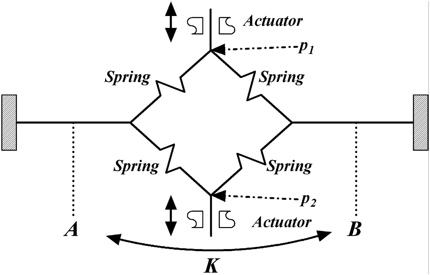
5.2.4. Electro-rheological/magnetorheological fluids and dampers
Electro-rheological, and MR fluids are suspensions of extremely fine (micron sized) ferroelectric and ferromagnetic particles dispersed in a carrier fluid, respectively (Stanway, 2004; Winslow, 1949). The change in viscosity of ER/MR fluids directly depends on the applied electric/magnitude field, and this characteristic makes ER/MR fluids attractive for providing a rapid response interface in controlled mechanical devices. The most common application of ER/MR fluids is the hydraulic valve, clutch, brake, and absorber (damper) (Bitman et al., 2002; Makris et al., 1996; Stanway, 2004). As one of the most promising semi-active devices, ER/MR dampers have been applied to the SAMD design by researchers. However, the complex nonlinear hysteresis phenomenon existing in the ER/MR devices, and its relative control methodologies, limit the application of the smart fluid dampers. Koo (2003) investigated the MR damper-based SAMD system. Yang et al. (2010a, 2010b) applied the LuGre friction MR damper model to the SAMD structures. Kim and Kang (2011) investigated an adaptive building-type structure utilizing MR damper as the semi-active damping device, which includes the SAMD design. Weber (2014) investigated the MR-based SAMD system on the basis of the force and displacement feedback. It is noted that although there are many research works on ER-/MR-based SAMD design, majority of them are focused on the development of control methodologies based on different models of the ER/MR devices due to the complexities associated with the nonlinear hysteresis properties of the MR devices.
5.2.5. Magnetorheological elastomer TMD vibration absorber
The MREs are solid state of MR materials. They are kind of composite materials consisting of the dispersed micron-sized magnetic particles in the rubbery polymeric matrix. The shear stiffness of the MRE can be changed rapidly in a wide range with the change of the applied magnetic field. Comparing with the magnetorheological fluids (MRFs), the MRE materials do not have sealing and packaging problems when used in the design of real applications [213]. Recently, MRE has been effectively utilized to provide variable stiffness semi-actively. Ginder et al. (2000) proposed a controllable stiffness component based on the MRE. Then, Ginder et al. (2001) extended their work to the tuned vibration absorber (TVA) system.
Deng et al. (2006) utilized the MRE as the AVS device to design a TVA system for beam-type structures, in which the natural frequency of the secondary system can be shifted from 55 (Hz) to 81.25 (Hz) respective to 0 (A) and 1.5 (A) input current. Behrooz et al. (2014) investigated a three-story building model with four AVS and variable damping isolator, which acts as the TVA system. Applying the MRE to the AVS system and then designing the TVA device are recent research thrust in the structural vibration isolation area. Li et al. (2014) recently presented a state-of-the art review on the MRE-based devices which covers most related research articles up to 2014.
There are other active/semi-active devices which can be utilized to design the SAMD system to shift the natural frequency of the secondary system. Alujević et al. (2012) utilized the PZT actuator to shift the stiffness of the secondary system. Similar work has also been conducted by Tso et al. (2013), Huang and Hung (2011), and Kim et al. (2011). Williams et al. (2005) and Rustighi et al. (2005) utilized the shape memory alloy as the active device to tune the stiffness of the secondary structures. The motor driving pendulum (rotation pendulum absorber) type SAMD is also the other kind of device, which has been investigated by the research group from Technische Universität Hamburg (https://www.tuhh.de/sdb), Körlin and Starossek (2007), and Wu et al. (2011). The electromagnetic force can also be applied to the SAMD to change the stiffness of the secondary system (Bae et al., 2012; Liu and Liu, 2006). Hirunyapruk et al. (2010) designed a sandwich beam with MR fluid as the core layer and attached electromagnets at end locations to perform as a tuned vibration absorber, in which the stiffness of the sandwich beam can be changed with the applied magnitude field.
5.3. Further development of TMD system
In Subsection 5.1, the typical realization of the TMD system has been summarized, and Subsection 5.2 summarized the semi-active and active TMD system. From the point of TMD design fundamental theory, there are not much change, and the main difference mainly lies on the optimization methodologies including the selected optimum objective function, whereas some combination of the modified TMD designs, as mentioned in Subsection 2.5, continues to appear. Recently, some research studies have focused on practical stiffness and/or friction models to the TMD design area, such as Chen et al. (2019). Generally, the practical stiffness and/or friction models are both nonlinear, and one can have many choices. In this review study, this direction can be considered as the nonlinear TMD design, which is out of scope of this study.
Based on the authors’ study, in the linear TMD design area, one area which has not been addressed properly is the boundary of the relative displacement of the main and attached secondary systems. In the traditional linear TMD design, no constraints have been considered for the relative displacement which may considerably affect the performance of the TMD system.
Utilization of smart materials, particularly semi-active MRF and MRE in development and design of adaptive TMD system is still in its infancy. Once of the main challenge is multidisciplinary design optimization of MRF-/MRE-based adaptive TVA in which magnetic and structural parameters are tackled simultaneously to increase the dynamic range of adaptive TMDs considering the limited stroke in MRF/MRE actuation devices. Another important topic in the area of adaptive TMDs is the development of robust control strategies considering the nonlinear hysteresis behavior of MRF and MRE materials.
6. Conclusions
In this article, a state-of-the-art review of the TMD system has been presented. The literature on TMD is vast, thus this review has mainly addressed research studies after 90s with primary focus on the TMD design and its modification; TMD design modeling for discrete and continuous structures; and the TMD design optimization procedures. General overview on development of the TMD design including devices, design concepts, and their real applications has also been presented. Finally, some practical realization of the TMD system has also been summarized. It has also been shown that the future research points related to the TMD area will be focused on the practical friction and/or stiffness model with design boundary, the semi-active/active TMD systems for development of adaptive structures to attenuate vibration in broad range of frequencies, and multidisciplinary design optimization of active and semi-active TMD systems.
Footnotes
Declaration of Conflicting Interests
The authors declared that there are no potential conflicts of interest with respect to the research, authorship, and/or publication of this article.
Funding
The author(s) disclosed receipt of the following financial support for the research, authorship, and/or publication of this article: The authors gratefully acknowledge the financial support received from the Natural Science and Engineering Research Council (NSERC) of Canada under Discovery Grant and the National Natural Science Foundation of China (NSFC) (Ref. 61733006 and U1813201) to conduct the research work presented in this article.