
Abstract
This study investigated the performance of a single-stage scroll compressed air source heat pump coupled with a flash tank indirect vapor injection. In the refrigerant circulating piping of the heat pump, an indirect vapor injection piping connecting a flash tank at the refrigerant outlet of a condenser and the suction of a scroll compressor was designed. By the indirect refrigerant vapor injection from the flash tank, the saturation pressure and temperature of the refrigerant (R134a) in the evaporator can be raised and the sub-cooling of the refrigerant at the inlet of expansion valve can be enlarged as well. Thus, energy consumption of the compressor can be reduced and cooling capacity of the evaporator can be boosted. It was found that the suitable amount of indirect vapor refrigerant strongly depends on the operational environmental temperatures. By adjusting the suitable indirect vapor injection volume into the compressor, the performance of the heat pump was enhanced. In this study, a suitable indirect vapor injection volume was found and 5~15% performance increments can be obtained while the heat pump operated under ambient temperatures in a range from 5°C to 35°C.
Keywords
Introduction
Global consumption of fossil energy increased by 33%–45% from 1990 to 2010, 1 exacerbating global warming. Stern 2 projected that economic losses due to global warming from 2007 to 2020 would amount to 13.8% of global gross domestic product (GDP). Due to these issues, demands for efficient energy consumption are continue to increase. To meet these demands, governments are working hard to strengthen CO2 emission controls, the standards for the certification of products, and companies are spurring the development of new technology to derive high efficiency of products. Also, the same demand is increasing for high efficiency in heating and cooling systems by growing customer recognition of the need for energy saving. The main objective of these efforts is to change the existing systems using fossil fuel into employing heat pumps for heating and cooling application.
The heat pump has a disadvantage in terms of its complicated structure, and its performance and the change of building load have an opposite trend. The demand of the system increases continuously because it has the high efficiency compared with existing heating systems. Also, the utility of heat pump is standing out by a technology development like inverter to respond effectively to the building load. 3 Recent studies in the area of refrigeration cycles, with regard to researches of more efficient systems, have concentrated their efforts mainly in two specific areas: the development of new technologies, using alternative cycles to obtain a better performance and the use of new refrigerants aiming both energetic and environmental aspects. Different alternative cycles have been studied and there are many promising options to increase the thermodynamic efficiency in comparison with the conventional vapor compression cycle. Currently, some of the most explored alternative refrigeration cycles are ejector refrigeration, cascade, and refrigerant injection systems. 4
For air source heat pump, the vapor injection technology has been applied in the system with two-stage compressor in order to cool the compressor and increase the super-cooling of the refrigerant condensation. Refrigerant vapor injection technique has been well justified to improve the performance of systems in refrigeration applications. 5 The vapor injection technique can effectively increase the system performance for both high ambient cooling application and low ambient heating application. 6 The experimental studies that conducted by Cho et al. 7 stated that the coefficient of performance (COP) of heat pump was 2.6%–7.0% higher than that without vapor injection. The vapor injection technology application on the refrigeration system and heat pump system has been attracted many scholars’ attentions these years.
It has been indicated by Xu et al. 8 that the refrigerant liquid level in the flash tank could be controlled effectively using high-pressure stage expansion control valve, low-pressure stage expansion control valve, and the injection valve on the auxiliary circuits and the fluid on the flash tank. The system could obtain the optimal refrigerant vapor injection quantity when the liquid level was controlled at 40%~60% of total height of flash tank. Xu et al. 9 mentioned the new type of cycle control strategy of R-410A vapor injection flash tank heat pump system for housing type. The system uses proportional–integral–derivative (PID) controller to control the opening of electronic expansion valve (EEV) in high-pressure stage and uses sensing bulb of thermostatic expansion valve (TXV) to control the opening of TXV in low-pressure stage. The vapor superheat sensor is mounted at the vapor injection opening on the auxiliary circuits to detect the superheat of refrigerant vapor injected into the compressor, which can provide a control signal for EEV. The system can control the opening of EEV on the high-pressure stage and TXV on the low-pressure stage according to the signal for internal liquid level control of flash tank. The study conducted by Roh and Kim 10 tested the system with compressor operating frequency of 60–100 Hz. The test result showed that the intermediate pressure could increase the heating capacity of condenser and system efficiency effectively, but it limited the applicability of vapor injection. An appropriate vapor injection control strategy has considerable effect on the system performance and capability. Xu et al. 11 studied the vapor injection flash tank heat pump system using R-410A refrigerant, the system used EEV for higher-pressure level expansion and TXV for lower-pressure level expansion, a small electric heater is applied to the evaporator injection line to import the steam generated by superheating, so as to provide a control signal for the EEV. The experimental results showed that the recommended value of flash tank liquid level controlled superheat was 4–6 K under transient and steady-state condition. As the PID can provide the control accuracy of EEV accurately, so this control strategy is regarded as a reliable periodic control strategy.
The vapor injection technology usually applied to the two-stage compressor system in order to increase the heating capacity of condenser and system efficiency effectively. 5 The performance of an injection cycle will depend on four internal variables: pressure, mass flow rated of the injected gas, superheat of injected gas, and the temperature of the refrigerant at the inlet of expansion valve. 12 With the increase of heat exchanger sub-cooling parameter, more refrigerants are “injected” to improve the sub-cooling effect obtained by the inter-stage configuration. As a result, the intermediate pressure rises so that the high-stage compressor mass flow rate is increased. For the same reason, the COP of the system is also enhanced. 13
Nowadays, the vapor injection system has also been implemented in single-stage vapor compression cycle in order to enhance the system’s performance. Xu et al. 14 conducted some research to enhance the single-stage vapor compression system’s performance by installing the flash tank in the outlet of expansion valve. They concluded that the cooling energy efficiency ratio (EER) of an optimized enhanced vapor injection system can be close to 4% and the cooling capacity can be 4% bigger than that of a single-stage system. Oquendo et al. 15 have compared the performance of a scroll compressor with vapor injection and two-stage reciprocating compressor, it is found that the scroll compressor with vapor injection presents better efficiency when working with pressure ratios below 7.5 approximately and also at moderate evaporating temperature conditions, and the scroll compressor with vapor injection develops higher cooling COP and capacity. Lee et al. 16 mentioned the sub-cooling for liquid injection as a proper parameter to control the injection for the reliable operation in the liquid injection case.
However, in this study, the vapor injection technology was applied to a single-stage scroll compressed air source heat pump. In the past, vapor injection system usually implemented on the two-stage heat pump and nowadays, its application is already started to be implemented in single-stage heat pump. In addition, the performance of the single-stage vapor injection system which tested under different ambient conditions becomes another aspect to be investigated, so that the effect can be observed and the research can be developed. In this study, the performance of the system was investigated under different ambient operational conditions.
In the past, the vapor injection technology was often applied to the two-stage compressed refrigeration system. Fewer studies have investigated the performance of the single-stage compressed heat pump system in detail, especially under different operational temperatures. In the study, the vaporous refrigerant from the flash tank is injected into the accumulator before entering the compressor instead of directly injected into the compressor. The vaporous refrigerant from the flash tank mixes with vaporous refrigerant from the evaporator in order to increase the superheat and enhance the performance of the heat pump. The performance of the single-stage compressed system utilizing the indirect vapor injection under different ambient temperatures was investigated in order to understand the amount of indirect injected vapor on the performance of the system under different ambient operational temperatures.
Experimental setup and test procedure
Experimental setup
The single-stage scroll air source heat pump system with indirect vapor injection loop can be divided into water cycle side and refrigerant cycle side, and the refrigerant cycle side can be divided into major loop and auxiliary loop. In terms of water cycle side, the heat pump system designed in this scheme is a cyclic heating system, the water pump circulates water to the plate heat exchanger and high-pressure side refrigerant for heat exchange, and the hot water enters the hot water storage tank for thermal storage.
On the refrigerant cycle side, the compressor discharges high-pressure and high-temperature gas refrigerant, which flows through the plate heat exchanger for heat exchange. The high-pressure and high-temperature liquid refrigerant flows out of the plate heat exchanger and enters the flash tank through drier, sight glass, and solenoid valve. The refrigerant of major loop exchanges heat with the refrigerant of auxiliary loop in the flash tank, so that the major loop refrigerant is cooled to subcooled liquid, which is turned by expansion valve into low-pressure and low-temperature liquid-vapor refrigerant, then it enters the evaporator to absorb environmental heat to become low-pressure and low-temperature vaporous refrigerant, and it merges the vaporous refrigerant of auxiliary loop in front of the accumulator inlet before entering the accumulator.
The high-pressure and high-temperature vaporous refrigerant is obtained after the heat is absorbed by heat exchange with the major loop refrigerant in flash tank; it flows in the auxiliary loop, depressurized by EEV, mixed with the vaporous refrigerant of major loop in front of the accumulator. The mixture of major loop and auxiliary loop refrigerants flows in the accumulator to guarantee the vapor state in the compressor, to avoid compressor liquid compression forming closed refrigerant cycle. When the electronic expansion valve mounted on the auxiliary loop is turned off, the system works as single-stage compression heat pump system. When the electronic expansion valve is partially turned on, the system becomes indirect vapor injection compression system. This practice can enhance the low-temperature adaptation of set and increase the sub-cooling of refrigerant cycle, the heating capacity of heat pump system and the performance of the system are increased. The system’s cycle piping diagram is shown in Figure 1.

Indirect vapor injection auxiliary loop air source heat pump system cycle diagram.
Test procedure
This study was conducted under different ambient temperatures, electronic expansion valve openings, and fixed initial storage tank water temperature (15°C) to test the performance of single-stage compression scroll heat pump system according to CNS15466 standard, the purpose is to discuss the performance of single-stage scroll heat pump system at different ambient temperatures and the appropriate vapor injection quantity at different ambient temperatures is obtained using the EEV opening to optimize the single-stage scroll heat pump system performance.
The equipment specifications of this system are as follows:
1. Water pump:
Output: 1/4 HP, 0.18 kW, voltage: 220 V, current: 1.5 A
2. Electric water heater:
Rated capacity: 30 L
3. Plate heat exchanger:
Number of condenser plates: 29 pcs, length: 306.0 mm, width: 106.0 mm, height: 80 mm
4. Evaporator:
Capacity: 5.81 kW, evaporating temperature (ET): –5°C, evaporator temperature difference (TD): 8°C
5. Compressor:
Power: 1.120 kWs
The performance of single-stage scroll heat pump system with different electronic expansion valve openings was measured in an environmental chamber with room temperature in a range of 5°C–35°C and fixed initial tank water temperature of 15°C. In order to obtain the performance trend map of single-stage scroll heat pump system at each electronic expansion valve opening and different ambient temperatures, this experimental method is used for test.
The heating capacity of the heat pump from the condenser can be calculated by

where
To calculate the power factor of the compressor, the following expression can be used

where cos θ is the power factor, P is the real power (VA), and S is the apparent power (VA).
The real power consumption of the compressor can also be calculated by

where W is the real power (W), V is the voltage (V), I is the supply current to the compressor (A), and cos θ is the power factor.
Therefore, the instant heating coefficient of performance (


where
Results and discussion
Performance of single-stage scroll heat pump system at ambient temperature of 5°C
Figure 2 shows the distributions of the COPh,avg value with the rise of the temperature at the outlet of the water storage tank for every electronic expansion valve opening position. In this case, the experiments were conducted in an ambient temperature of 5°C. After the system started to operate, the tank water temperature gradually increased from the initial value of 15°C. The system reached the highest COPh,avg value of 2.71 while the water storage tank temperature was 40°C under 0% electronic expansion valve opening. Furthermore, under different water tank temperatures, the system under EEV opening position of 0% possessed higher COPh,avg in comparison to the other cases. From Figure 2, it can also be found that although the overall values of COPh,avg declined by the rising of water temperature, the declination of the system at EEV opening of 0% is less in comparison to the other cases with different EEV opening positions.

From the COPh,avg distribution, when the water in the storage tank rises to high temperature, the electronic expansion valve should gradually close its opening position in order to maintain the high performance of the system. The reason is that with the increase in the water temperature, the condensate pressure increases as well, which may cause larger vaporous refrigerant to be injected into the auxiliary circuit. If too large flow rate of refrigerant vapor is introduced into the vapor injection circuit, the flow rate of refrigerant entering the evaporator to absorb heat from the outside environment proportionally decreases, which may result in the decreased cooling capacity of the system and COPh,avg value. From Figure 2, it can be seen that the flow rate of the refrigerant vapor injected into auxiliary circuit should be suitably controlled in order to maintain high performance of the heat pump system. Introducing a suitable flow rate of refrigerant vapor into the auxiliary circuit can be beneficial in boosting the performance of the system; however, an excessive flow rate of refrigerant vapor introduced may worsen the performance of the system. From Figure 2, it is found that the performance reduction of the system due to water temperature rising from 40°C to 55°C at EEV opening of 0% is about 14.7%, at EEV opening of 33% is 19.36%, at EEV opening of 66% is 33.85%, and at EEV opening of 100% is 43.20%.
Table 1 illustrates the superheat and sub-cooling degrees of the system at an ambient temperature of 5°C, with the water temperature rising from 40°C to 55°C under different opening positions of the electronic expansion valve. The definition of superheat degree refers to the difference between the refrigerant temperature at the suction line of the compressor and the evaporation temperature of the refrigerant in the evaporator. The refrigerant at the outlet of evaporator is blended with refrigerant from the vapor injection circuit and then the mixed refrigerant enters the accumulator. In the accumulator, the low pressure generated by the suction of the compressor causes some liquid refrigerant to evaporate and absorb the heat from the other liquid refrigerant in the accumulator, which leads to lower refrigerant vapor temperature at the suction line of the compressor in comparison to that in the evaporator. Thus, some superheat degrees have negative values in Table 1. In the case of the 0% electronic expansion valve opening, when the water temperature is 40°C, the superheat degree is low (0.12°C) and the sub-cooling degree is high (6.06°C). Lower superheat degree is beneficial to the operational efficiency of the compressor and higher sub-cooling degree can boost the refrigeration effect of the refrigeration cycle. Therefore, the instant COP of the system at the time of water temperature of 40°C is the highest among the cases shown in Figure 2. With the increase in the water temperature, the condensing pressure increases as well, which leads to more vapor injected into the auxiliary circuit. Thus, the sub-cooling degrees in the cases with the electronic expansion valve opening gradually increase with the increase in the water temperature. However, in the case without the electronic expansion valve opening, the sub-cooling degree does not apparently vary with the water temperature and remains in a range of 5°C–6°C.
Superheat and sub-cooling degrees distribution at ambient temperature of 5°C.

Unit: °C
On the other hand, for the superheat degree, as the water temperature increases, the intermediate pressure of the vapor injection auxiliary circuit increases as well. Thus, superheat degrees in the cases with the electronic expansion valve opening gradually rise with the increased water temperature. However, in the case without the electronic expansion valve opening, the superheat degree does not apparently vary with the water temperature and remains in a range of −1°C to 0°C.
In terms of the COPh,avg value of the system, a greatly sub-cooling degree is beneficial to the refrigeration effect of the system, but it means that a large proportion of refrigerant vapor is introduced into the auxiliary indirect vapor injection circuit as well, which may result in the decreased refrigeration capability of the system and an excessive rise of the superheat degree. These phenomena may cause the COPh,avg value in the cases with the electronic expansion valve opening to dramatically decline with the increased water temperature. However, in the case without indirect vapor injection, the COPh,avg value declination is not severe in comparison with the cases with the electronic expansion valve opening under an ambient temperature of 5°C. As the declination of superheat and sub-cooling degrees in case of 0% EEV opening position are not severe, the performance reduction of the system is also quite low in comparison to the other cases.
Figure 3 shows the compression ratio of the heat pump at different opening positions of the electronic expansion valve in the auxiliary circuit and different water temperatures in the tank. However, the ambient temperature is maintained at 5°C. Figure 3 is purposed to find out the indirect vapor injection effect on the compression ratio of the heat pump under different condensation temperatures. As shown in Figure 3, with the increase in the water temperature, the condensate pressure of the refrigerant should be raised in order to effectively dissipate the heat absorbed from the evaporator. Thus, higher power consumption was necessary for the compressor to boost the discharging pressure of the compressor with the rise in the water temperature. As shown in Figure 3, in all cases, the compression ratios gradually increase with the increased water temperature. From Figure 3, it can be seen that in the cases with indirect vapor injection, because the injected vapor possesses a higher pressure in comparison to that of the refrigerant stream from the evaporator, the suction pressure of the compressor from the mixing streams of the indirect vapor injection and the evaporator were higher than in the case without indirect vapor injection. Therefore, as shown in Figure 3, in the cases with larger opening positions of the electronic expansion valve in the auxiliary circuit, the corresponding compressor ratios were less.

Compression ratio distribution under different water temperatures at ambient temperature of 5°C.
As shown in Figure 3, when the water temperature reached 50°C, the compression ratio of the system without indirect vapor injection could reach a value of 6.1; however, in the case with 100% opening position of the electronic expansion valve in the auxiliary circuit, the compression ratio value was about 4, which is 2.1 points less than in the case without indirect vapor injection. A lower compression ratio means the compressing efficiency can be enhanced and less energy is required for the compressor.
Table 2 lists the evaporator pressure (low pressure), indirect vapor injection pressure (intermediate pressure), and discharge pressure (high pressure) of the system under different operational conditions of different opening positions of the electronic expansion valve and at different water temperatures. It can be seen that the indirect vapor injection pressures in the cases with different opening positions were always greater than the corresponding evaporator pressures at different water temperatures, which led to higher suction pressures in comparison to those in the case without indirect vapor injection. In Table 2, it can be seen that with the increase in the water temperature, both the suction pressure and discharge pressure rose as well. However, the increments of discharge pressure are greater than those of the suction pressure; thus, the compression ratio rose with the increased water temperature. In the cases, when the water temperature reached 55°C, the discharge pressures were about 15 bar; however, the suction pressures in the cases with indirect vapor injection increased with the rise in the opening position. This is the reason that the case with full opening of indirect vapor injection possesses the lowest compression ratio among the cases. The lower compression ratio means the system can operate with higher compressing efficiency and lower required energy consumption.
Evaporator pressure, indirect vapor injection pressure, and discharge pressure of the system at different opening positions of expansion valve and at different water temperatures under ambient temperature of 5°C.
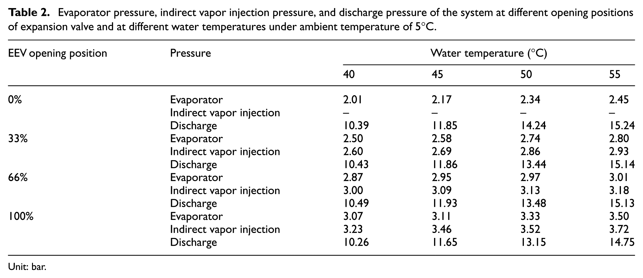
Unit: bar.
Performance of single-stage scroll heat pump system at ambient temperature of 15°C
Figure 4 shows the distribution of the COPh,avg value of the system at an ambient temperature of 15°C under different electronic expansion valve opening positions. From Figure 4, it can be found that the highest COPh,avg value of 3.36 can be attended when the electronic expansion valve opening position is 100% at water temperature of 40°C. However, when the water storage tank temperature was heated to higher temperatures, the COPh,avg value in the case of the electronic expansion valve fully opened shows a massive declination. When the water tank temperature rose to 45°C, in the case of the closed electronic expansion valve, the greatest average performance resulted among the other cases investigated. From Figure 4, it was found that the performance reduction of the system due to water temperature rising from 40°C to 55°C at EEV opening of 0% is about 11.80%, at EEV opening of 33% is 10.62%, at EEV opening of 66% is about 16.17%, and at EEV opening of 100% is 24.38%. In case of 100% EEV opening, the performance of the heat pump is dropping rapidly due to an excessive amount of refrigerant introduced to auxiliary loop. As too much refrigerant introduced to accumulator by auxiliary loop, the cooling capacity of the evaporator is reduced and the performance of the heat pump becomes worse.
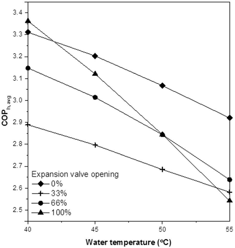
Table 3 illustrates the superheat and sub-cooling degrees of the system at an ambient temperature of 15°C and water temperature rising from 40°C to 55°C under different electronic expansion valve opening positions. As shown in Table 3, the case of 33% EEV opening position possessed high sub-cooling degree but low superheat degree. Thus, the declination of COPh,avg in the case was the slightest among the cases. Excessive amounts of refrigerant including liquid refrigerant introduced to the auxiliary loop may reduce the performance of the system. The liquid refrigerant accumulated at the bottom of the accumulator and some of the liquid refrigerant evaporated into vapor due to the suction of the compressor, which lowered the suction temperature below the evaporating temperature. The excessive amounts of refrigerant introduced into the auxiliary circuit may reduce the cooling capacities and cause the COPh,avg to be declined in the cases with indirect vapor injection.
Superheat and sub-cooling degrees distribution at ambient temperature of 15°C.

Unit: °C.
Performance of single-stage scroll heat pump system at ambient temperature of 20°C
Figure 5 shows the COPh,avg value distribution of the system under an ambient temperature of 20°C for every electronic expansion valve opening position. It can be seen from Figure 5 that when the system is operated under an ambient temperature of 20°C, the system average performance improvement by indirect vapor injection is obvious. In comparison to the case of an ambient temperature of 5°C, with an ambient temperature of 20°C, heat can be easily absorbed by the evaporator, and the compression ratio can be reduced due to the refrigerant vapor injection; thus, the compressor power consumption can be reduced indirectly as well. In the case of 66% electronic expansion valve opening position, the maximum COPh,avg value can reach to a value of 3.95 at a water temperature of 40°C. However, with the increased water temperature, the COPh,avg declines severely in comparison to the other cases with different electronic expansion valve opening positions. Therefore, the COPh,avg distributions suggest that with the rising water temperature, the opening degree of the electronic expansion valve can be reduced gradually from the initial opening position of 66% in order to increase the rate of the refrigerant flow moving into the evaporating circuit, and the corresponding cooling capacity of the system. When the water temperature reaches 55°C, the electronic expansion valve is suggested to be fully closed in order to retard the performance reduction of the system. From Figure 5, it was found that the performance reduction of the system due to water temperature rising from 40°C to 55°C at EEV opening of 0% is 10.12%, at EEV opening of 33% is 13.56%, at EEV opening of 66% is 18.38%, and at EEV opening of 100% is 16.16%.

Table 4 shows the superheat and sub-cooling degrees of the system at an ambient temperature of 20°C. In comparison to the system operated at a low ambient temperature of 5°C, the system operated at an ambient temperature of 20°C possesses higher evaporation and intermediate pressures. Thus, with the rising water temperature, the superheat degrees increase slightly as well under different water temperatures. On the other hand, the sub-cooling degrees apparently rise with the increased water temperature as well. As a result, the performance of the system operating under higher ambient temperatures is greater than that operating under lower ambient temperatures in terms of the increase of the superheat and sub-cooling degrees. When the water temperature is 40°C, the case of the 66% electronic expansion valve opening possesses a higher sub-cooling degree but a lower superheat degree. Thus, the system performance COPh,avg in this case possessed the highest value in comparison to the other cases with different openings. However, with the increased water temperature, the superheat degree of the case apparently rose as well, which led to a severe performance declination in comparison to other cases in Table 4. However, when the temperature reached 55°C, the performance of the case of the 66% opening still possessed the highest value among the cases in Table 4.
Superheat and sub-cooling degrees distribution at ambient temperature of 20°C.

Unit: °C.
Performance of single-stage scroll heat pump system at ambient temperature of 25°C
Figure 6 shows the distributions of COPh,avg value at an ambient temperature of 25°C. In comparison to the case of the lower ambient temperature of 20°C in Figure 5, a full opening of the indirect vapor injection electronic expansion valve is recommended when the water temperature is 40°C in order to attain a higher COPh,avg performance, as shown in Figure 6. However, as the water temperature rises to higher temperatures, the system average performance of the case declines severely in comparison to the other cases with less openings of the indirect vapor injection electronic expansion valve. It can be observed that when the temperature rises from 40°C to 55°C, in the case of 33% opening of the indirect vapor injection electronic expansion valve, the declination of COPh,avg with the increase in water temperature is the least among the cases. Thus, when the water temperature is rising, the opening of the indirect vapor injection electronic expansion valve is recommended to be gradually reduced in order to maintain high system operational performance. From Figure 6, it was found that the performance reduction of the system due to water temperature rise from 40°C to 55°C at EEV opening of 0% is about 10.32%, at EEV opening of 33% is 8.08%, at EEV opening of 66% is 13.10%, and at EEV opening of 100% is 14.78%.

Table 5 lists the superheat and sub-cooling degrees at ambient temperature 25C under different EEV opening positions. From Table 5, when the water temperature is 40°C, the case of the 100% electronic expansion valve opening yielded a higher sub-cooling degree but a lower superheat degree. Thus, the system performance of the COPh,avg in the case possessed the highest value in comparison to the other cases with different openings. However, in the case when the water temperature was greater than 40°C, the superheat degree increased greatly with the increased water temperature; thus, the value of the COPh,avg declined severely in terms of the water temperature.
Superheat and sub-cooling degrees distribution at ambient temperature of 25°C.

Unit: °C.
Performance of single-stage scroll heat pump system at ambient temperature of 35°C
Figure 7 shows the COPh,avg value distributions at an ambient temperature of 35°C. From Figure 7, it can be found that when the water temperature is 40°C, the case of electronic expansion valve opening of 100% possessed the highest performance of COPh,avg value of 4.13. However, after the water temperature rise to 45°C, the performance of the case decreases gradually and the case of without indirect vapor injection possessed the best performance of the system. In this case, as the water temperature rises from this point, the electronic expansion valve must be closed gradually in order to maintain the system operating at the best performance. From Figure 7, it was found that the performance reduction of the system due to water temperature rise from 40°C to 55°C at EEV opening of 0% is about 15.71%, at EEV opening of 33% is 8.41%, at EEV opening of 66% is 15.85%, and at EEV opening of 100% is 16.35%.
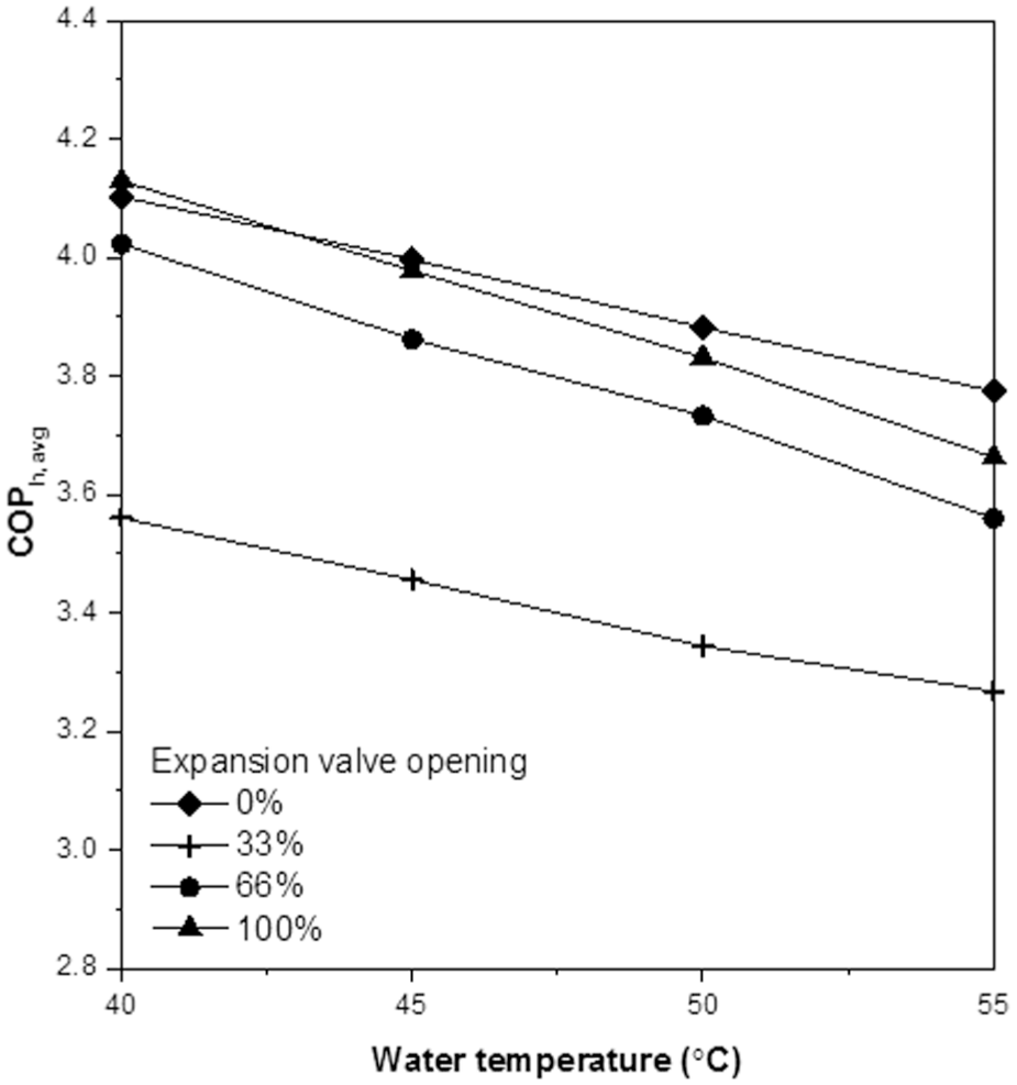
Table 6 lists the superheat and sub-cooling degrees under an ambient temperature of 35°C under different electronic expansion valve opening positions. The case of a closing electronic expansion valve possesses a higher sub-cooling degree and a lower superheat degree. Thus, the system performance COPh,avg in the case possessed the highest value in comparison to the other cases with different openings. It is observed from Table 6 that at high ambient temperature, the evaporating temperature increases as well. At the same electronic expansion valve opening positions, the flow rates of indirect refrigerant vapor injection are less than those under lower ambient operational temperatures due to the higher evaporating temperatures under higher ambient temperature. Thus, the increasing of sub-cooling degrees by the indirect vapor injection are not apparent in comparison to those under lower ambient operational temperature. Thus, under higher operational temperatures, the average performance enhancement by the indirect vapor injection is not apparent in comparison to those in the cases of ambient temperatures of 25°C and 30°C.
Superheat and sub-cooling degrees distribution at ambient temperature of 35°C.
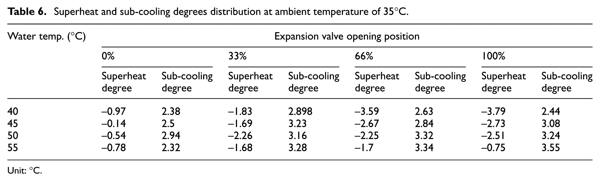
Unit: °C.
With regard to the compression ratio, the cases of an ambient temperatures varying from 10°C to 35°C show a similar trend to the case of an ambient temperature of 5°C. The compression ratio increased as the water temperature rose. The case with the indirect vapor injection had a much lower compression ratio than the case without indirect vapor injection.
Conclusion
This study investigated the performance of a single-stage air source heat pump integrated with a flash tank under different opening positions of indirect vapor injection electronic expansion valve and different operational environments to enable the air source heat pump to work normally in low-temperature environment. The air source heat pump is characterized by high efficiency, low energy consumption, and pollution free, but in cold condition, the system operating performance is influenced significantly. The compression ratio increases as the ambient temperature decreases, the compression efficiency decreases, and the heating performance declines, the compressor may even be burnt.
The flash tank in auxiliary loop is used in this study, if the electronic expansion valve (EEV) opening in the auxiliary loop is too large, there may be overall system bypass, so that the refrigerant cycle only passes through the auxiliary loop instead of main loop of the system, the overall benefit is worsened; on the contrary, the average system heating performance (
Footnotes
Handling Editor: Stephen D Prior
Declaration of conflicting interests
The author(s) declared no potential conflicts of interest with respect to the research, authorship, and/or publication of this article.
Funding
The author(s) disclosed receipt of the following financial support for the research, authorship, and/or publication of this article: The author gratefully acknowledges the financial support provided to this study by the Ministry of Science and Technology of Taiwan under grant no. MOST 104-2221-E-167-026-MY2 and MOST 104-2622-E-167-015-CC3.