
Abstract
In order to improve the speed control performance on the heavy load driving system of servo press, a control strategy based on speed observer with load torque identification and feed-forward compensation was proposed. It can identify and compensate the actual applied load torque by adjusting the machine quadrature axis current in real time. By identifying the problem in the traditional current feedback decoupling control scheme, a current vector control strategy based on voltage feed-forward decoupling control was proposed. Simulation analysis and experimental tests on a heavy load drive system were carried out using the proposed new control strategy. The results show that the control strategy is effective and the system designed by this method not only can identify the operating speed applied load torque, but also has good speed control performance.
Keywords
Introduction
The heavy load driving system used in the traditional mechanical press device consists of constant speed induction motor and mechanical flywheel. But the large inertia of the mechanical flywheel leads to small slip operation of the induction motor. The rotational speed of the rotating system after the flywheel is approximately constant in one cycle. It is then difficult to regulate the speed of this kind of drive system and the processing adaptability of the press machine is poor.1–3 Choi et al.4–10 analyzed its dynamics, noise, stamping performance, and other aspects from the mechanical structure point of view and pointed out that by changing to variable speed drive, the system can achieve high efficiency, high precision, and high flexibility. For example, Dulger et al.11,12 used variable frequency induction motor and mechanical flywheel as the drive train. The mechanical flywheel was driven by a high-slip induction motor and was used to store energy. During the stamping process, the flywheel was used for releasing the energy to compensate the peak load required in the stamping process; speed transducer was used to realize induction motor speed control. However, the flywheel drive system needs flywheel to provide energy for stamping, and during this transient period, the speed of the flywheel to reduces, which may reduce the required stamping force. The reduced speed will also reduce the number of strokes available for stamping within a given time period. Zhao et al.13–15 used the switched reluctance to replace the existing press drive system and improved the transmission structure. But it suffers from poor speed control accuracy and the precision of the designed press is not high. Liang et al. 16 used brushless direct current motor and the non-inertia “electronic flywheel” energy storage device to replace the asynchronous motor and the mechanical flywheel. The system is more compact and better dynamics in storing and releasing the energy. But it has large speed fluctuation in steady-state and stamping operation processes, and it also not suitable for high precision stamping operation. Huo et al.17–22 used the permanent magnet synchronous motor and “electronic flywheel” energy storage device to design press machine. It has the driving performance characteristics of high controllability, high precision, high flexibility, and high efficiency. It has become an important trend in the research and development of servo press system. However, in order to achieve a wide speed range operation and short acceleration (deceleration) time, not only the “electronic flywheel” energy storage device is needed for providing the energy for the acceleration process and recovering the energy in the reduction process, but also it is used to provide instantaneous peak energy required in the stamping process. This can be achieved by properly designing the “electronic flywheel” energy storage device and the control strategy used in the drive system. For example, Lu et al. 18 analyzed the working mode of servo press and the variation of the voltage and current of the capacitor energy storage device during the stamping process for a 80 ton servo press system. The model of heavy servo drive system was built based and the selection of parameters of capacitor energy storage was analyzed by simulation; energy storage device parameters were recommended. It has been proved that the dynamic system scheme has the characteristics of high power and high overload capability, and it is feasible to apply in servo press situation. Lu et al. 19 brief analyzed the design the capacitor energy storage device for servo motor drive system working at constant speed. In order to realize the variable speed drive and improved adaptability of the press machine, detailed analysis of controlling parameter of the servo driver was given. The results show that the designed capacitor energy storage device is able to meet the processing power and control requirements during the stamping process. In order to reduce the manpower and material cost and provide solid guidelines for design and optimization of the integrated mechanical and electrical system used in crank servo press, Wang et al.20,21 developed a simulation platform for analyzing crank servo press system. Lu 22 made a theoretical analysis of power system parameters of the servo system, includes the electrical parameters of the permanent magnet synchronous motor and the capacitance of the capacitor energy storage device, and given an approximate analytic expression. It also aimed to develop a 80 ton servo press system, with theoretical and experimental validations. The results of the first test showed that the error between the capacitance group power assisting coefficient and its theoretical value is 13%, so the theoretical derivation of the power system parameters is reasonable. It provides an effective theoretical analysis method for the development and optimization of the crank servo press system. However, none of the existing research methods have been used to study the control strategy of the drive system. The method used at present is just a set of mutually independent pre-debugging speed loop proportional–integral (PI) regulator parameters to meet the drive requirements. When the object to be stamped is different, its requirements on stamping speed and output force are different. The PI parameters need then to be adjusted manully and is not an efficient and reliable solution. When the motor is overloaded, the motor current is large, the system may cause overheating of the motor, and excessive torque ripple may occur. Therefore, it will reduce the operation efficiency and reliability of the permanent magnet synchronous motor. For the reasons mentioned above, the parameters of “electronic flywheel” energy storage device will be designed based on the following guidelines given in Du et al. 22 and the simulation, test, and analysis of the heavy load driving system with feed-forward and decoupling control strategy will be carried out in this article.
Analysis of the crank servo press whole system
The block diagram of crank servo press machine system based on the “electronic flywheel” energy storage device is shown in Figure 1. It consists of the “electronic flywheel” energy storage device, the heavy load servo driver, the embedded motion controller, the permanent magnet synchronous motor, the rotating transformer, and the press mechanical transmission mechanism. The “electronic flywheel” energy storage is achieved using a voltage-source inverter with a large capacitor. It includes the three-phase input reactor, the rectifier bridge, the capacitor bank, the energy consumption braking circuit, the inverter module, and so on. A detailed design of the three-phase input reactor, the rectifier bridge and inverter modules, and the selection of the capacitance of the capacitor bank was carried out in Du et al. 22 This article follows the same design guidelines and carried out a similar design for a 80 ton crank servo press as an application example. The electronic flywheel energy storage device and the permanent magnet synchronous motor together form the power delivering unit of the crank servo press; the embedded motion controller generates a reference speed command and closed-speed-loop control of the permanent magnet motor secures the actual motor speed follows the commanded speed. The rotating transformer is used to provide the actual position information of the motor. The motor control is aimed to achieve acceleration or deceleration operations with no load (t0–t2 and t3–t6 interval) and punch operation with load (t2–t3 interval), as shown in Figure 2(a). It should be noted that the speed of the permanent magnet motor will reduce when sudden heavy load (as shown in Figure 2(b)) is applied. The material processing accuracy is closely related to speed at the stamping stage. In order to keep a constant speed during the whole stamping stage, besides using the aforementioned “electronic flywheel” energy storage unit for delivering high peak energy to the motor, method on how to quickly and accurately reject the heavy load disturbance to the motor should be studied.

The functional block diagram of crank servo press machine system based on the “electronic flywheel” energy storage device.

Motor load characteristic curve: (a) crank motion curve and (b) motor load characteristic curve.
Research on heavy load servo driving system
Load torque identification and feed-forward compensation control
To suppress effectively sudden load torque disturbances, it is necessary to first introduce the load torque identification and feed-forward compensation control method, and its principle is described as follows.
The kinematic equation of the motor is


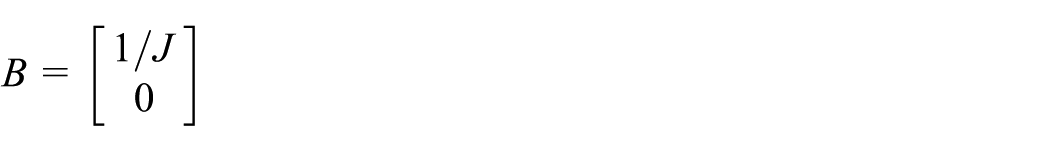
where
The sampling frequency of the controller is much higher than that of the change of the disturbance torque, so the load disturbance torque as a state variable can be assumed to be constant during a controller sampling interval, and its time derivative is therefore zero.
Let

This article adopts reduced order state observer. The reduced order dynamic state equations of the motor are as follows

where


According to equation (4), this article proposes a simple reduced order load observer as equation (5)

where
According to equations (4) and (5), we can get

where

Selecting an appropriate k value and letting
According to the specified desired pole

According to equations (7) and (8), we can obtain

Assuming

Equation (5) can be changed to equation (11) as

According to the characteristics of the system expected, selecting the location of the pole, structuring the observer based on equation (11), it is observed that the value of the load torque

where
The current loop may be made equivalent to a first-order inertia transfer function. The load observer for real-time identification of the actual load (
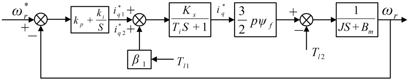
The speed control block diagram based on load torque identification and compensation.
According to the control block diagram of Figure 3, the static characteristic equation of the speed control loop can be derived as

In formula (13),
The current decoupling control based on the voltage feed-forward compensation
Traditional closed-loop current control scheme uses two PI regulators to independently control the d-, q-axis currents, as shown in Figure 4.
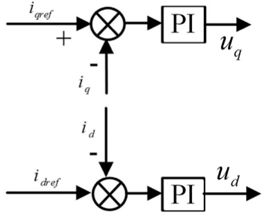
The current closed-loop control based on traditional PI regulator.
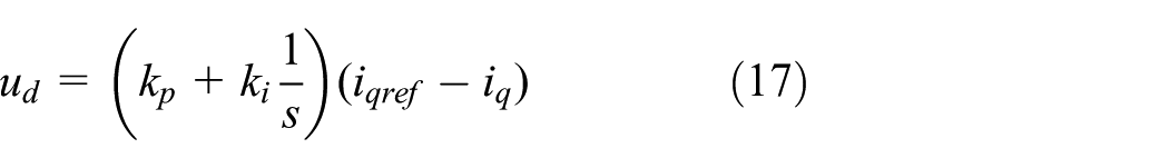
When using the voltage type inverter, its voltage component expressed in the dq-reference frame is


Transforming formulas (15) and (16) into frequency domain, we may obtain

The control variables


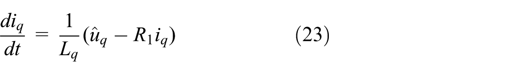
According to equations (19) and (20), when using the traditional PI regulator, the state equation has the cross-coupling term. Part of the output voltage of the traditional PI regulator is actaually used to counteract the back electromotive force; the rest is used to control the current. This not only increases the regulation time, but also reduces the adjustment precision and the dynamic performance of the system. Decoupled PI controllers (equations (20) and (21)) are used. Considering the machine voltage equations in dq-reference frame


Substituting equations (21) and (22) into equations (19) and (20), we can obtain

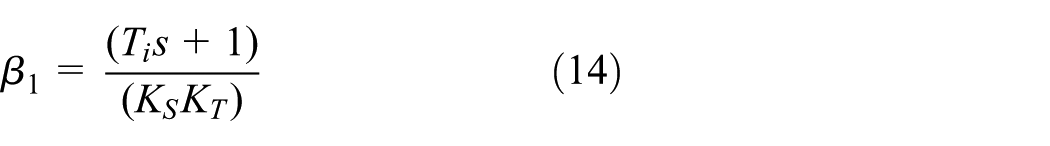
Decouple regulation of the d-, q-axis current is achieved. The block diagram of the decoupled PI controllers is shown in Figure 5. In this method, by introducing the feed-forward compensation term to counteract the coupling term in the stator voltages, disturbances caused by cross-coupling are suppressed. In this implementation,

The block diagram of the voltage feed-forward decoupling control.
System block diagram
Based on above analysis, the proposed control system is suitable for press overload drive and its topology is shown in Figure 6. It adopts

The control scheme block diagram of the servo motor drive system based on feed-forward and compensation.
Simulation analysis on heavy load servo driving system
The effectiveness analysis of the load torque identification algorithm
Firstly, the algorithm was simulated and analyzed under the condition of constant speed with a sudden load torque change. The given speed is 1000 r/min and the load torque experiences a step change from 0 to 10 N m at 0.06 s, as shown in Figure 7(a). The simulated waveforms of the estimated speed and estimated load torque are shown in Figure 7(b). The waveforms of the actual speed, the quadrature axis current, and the direct axis current are shown in Figure 7(c). It can be seen that the actual speed of the motor is 1000 r/min with 16 ms response time and the estimated speed is consistent with the actual speed. The estimated value of load torque is 0 before 0.06 s and it changes to 10 N m at 0.06 s with 6.5 ms estimation time. And the estimated error is only 0.2%. It can be seen from Figure 7(c) that the quadrature axis current is increased to 8.5 A and the actual speed dropped from 1000 to 980 r/min during the load change dynamics. The speed drop is about 20 r/min under the condition of constant speed with a step load torque change. The estimated speed and load torque are both in good agreements with the actual values.

The waveforms of the load torque identification algorithm under constant speed: (a) the given speed and load of the motor, (b) the estimated speed and the estimated load torque, and (c) the actual speed, the quadrature axis current, and the direct axis current.
Second, the algorithm was simulated and analyzed under the condition of variable speed with load torque change. The given speed is changed between 200 and −200 r/min and the load torque is changed suddenly from 0 to 10 N m at 0.06 s, as shown in Figure 8(a). The simulated waveforms of the estimated speed and estimated load torque are shown in Figure 8(b). The waveforms of the actual speed, the quadrature axis current, and the direct axis current are shown in Figure 8(c). It can be seen that the actual speed of the motor is 200 r/min with 4.5 ms response time and the estimated speed is consistent with the actual speed. The estimated load torque is 0 before 0.06 s and it changed to 10 N m when the given load is changed at 0.06 s. The estimation time is 6.5 ms and the estimated error is only 0.2%. The response time becomes longer (from 4.5 to 6.25 ms) in this simulation. The steady-state speed is dropped to 175 r/min after load torque change and the error is approximate 25 r/min. It can be seen from Figure 8(c) that the quadrature axis current is 19 A in the acceleration process. The proposed observer has high estimation accuracy of the speed and load torque; its estimation response time is short and is not affected by the motor speed operating mode.
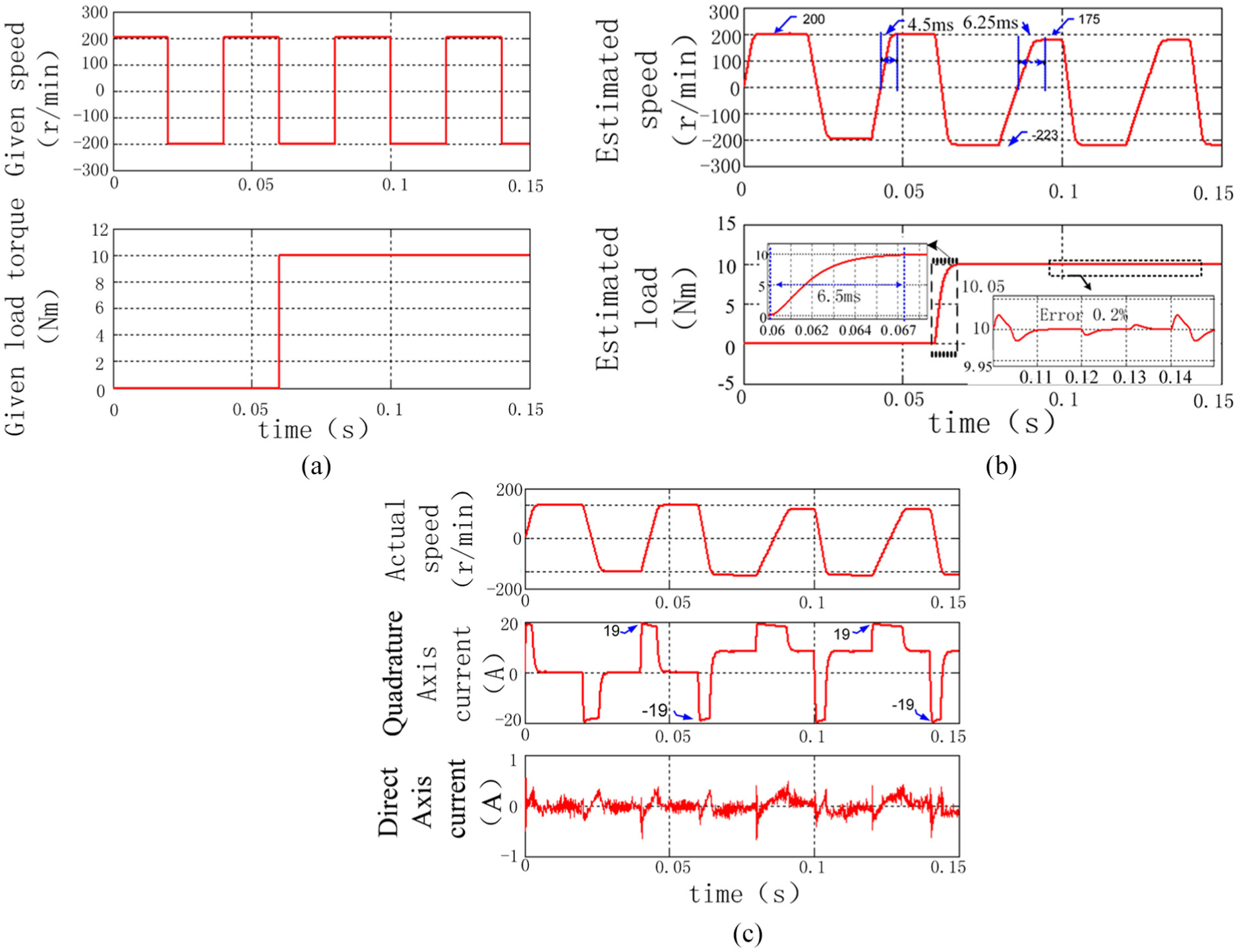
The waveforms of reduced order observer parameters identification with variable speed: (a) the given speed and load of the motor, (b) the estimated speed and the estimated load torque, and (c) the actual speed, the quadrature axis current, and the direct axis current.
The effectiveness of the system combined with two control methods
The system with two control methods was simulated and analyzed under the condition of constant speed with a step load torque change. The given speed is 1000 r/min and the load torque is changed suddenly from 0 to 10 N m at 0.06 s. The simulated waveforms are shown in Figure 9(a) and (b). It can be seen that the operation performance of the system with two control methods is consistent with it without using two control methods at the load mutation process, as shown in Figure 7(b). But the quadrature axis current is increased to 10 A and the actual speed dropped only from 1000 to 994 r/min, when the load torque is changed suddenly at 0.06 s. There is only a small drop about 6 r/min and the speed quickly returned to 1000 r/min after 6 ms.

The waveforms of the system with two control methods under constant speed: (a) the actual speed, the quadrature axis current, and the direct axis current and (b) the estimated speed and the estimated load torque.
Second, the system with two control methods was simulated and analyzed under the condition of variable speed with a load torque change. The given speed is changed between 200 and −200 r/min and the load torque is changed suddenly from 0 to 10 N m at 0.06 s. The waveforms of the actual speed, the quadrature axis current, the direct axis current, the estimated speed, and the estimated load torque are shown in Figure 10(a) and (b), respectively. It can be seen that the operation performance of the system with two control methods is consistent with it without using two control methods at load changed, as shown in Figure 8(b). But the quadrature axis current is increased to 27.5 A in the acceleration process and the rise time is reduced to 5 ms at 0.06 s, when the load torque is changed suddenly. The response performance is compensated, and the steady-state speed is 199.5 r/min. The speed drop is also greatly compensated. Therefore, the system based on the load torque observer and the feed-forward compensation algorithm has good performance in suppressing the effects caused by load torque change.
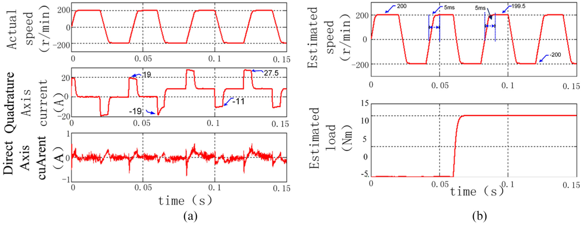
The waveforms of the system with two control methods under variable speed: (a) the actual speed, the quadrature axis current, and the direct axis current and (b) the estimated speed and the estimated load torque.
Experimental test on heavy load servo driving system
In order to validate the theoretical analysis and simulation results of the drive performance applied to a 80 ton servo press system was tested. The system structure and the experimental platform are shown in Figures 11 and 12, respectively. It consists of the speed servo driver, the permanent magnet synchronous motor, the capacitor energy storage device, the embedded motion controller, the crank link mechanism, and so on. The permanent magnet synchronous motor and the capacitor energy storage device are designed to allow four times overload operation. In the stamping process, the rated operating speed of the motor designed for this crank servo press is 500 r/min.

The system structure of the power driving device.

The experiment platform of the power driving device: (a) the speed servo driver, (b) the permanent magnet synchronous motor, (c) the capacitor energy storage device, (d) the embedded motion controller, and (e) the crank link mechanism.
The speed control performance is first simulated by applying the same working condition in the experiment. The results are shown in Figure 13(a) and (b). In Figure 13(a), we can observe that first, the motor is running at 500 r/min in steady state with no load; then the motor speed drops to 410 r/min and the speed error is approximately 90 r/min when the load torque is applied. In Figure 13(b), we can observe that the corresponding speed drop under the same condition is from 500 to 482 r/min only. The speed error is approximately 18 r/min when the same load torque is applied. Therefore, it can be seen that with load torque disturbance compensation, the steady-state speed error is greatly reduced.

The simulation waveform of the disturbance control algorithm: (a) without disturbance compensation algorithm and (b) with the disturbance compensation algorithm.
The experimental results corresponding to Figure 13 are shown in Figure 14(a) and (b). In Figure 14(a), the motor is first running at 500 r/min in the steady state with no load. Then the motor speed drops to 432 r/min and the speed error is approximately 68 r/min when the load is applied. In Figure 14(b), with disturbance compensation added, the speed drop is only 29 r/min (from 500 to 471 r/min). The experimental results are in good agreements with simulation results. The disturbance control algorithm proposed in this article is efficient, and it improves the performance when the drive system faces time-variable load.

The experiment waveform of the disturbance control algorithm: (a) without disturbance compensation algorithm and (b) with the disturbance compensation algorithm.
Conclusion
This article proposes a control method based on feed-forward and load torque compensation for heavy load driving system of crank servo press. Through the system modeling, performance simulation analysis, and experimental tests, the followings are concluded:
The control strategy which is proposed based on the load torque identification and the feed-forward compensation of the speed observer can detect the actual load torque change and can effectively compensate it in real time.
The current vector control strategy which is proposed based on voltage feed-forward cross-decoupling can improve the performance of the traditional PI current controller.
The system designed by integrating these two control methods has good speed control performance. The control strategy is effective and can achieve better speed control performance against load control change.
Footnotes
Acknowledgements
W.L. conceived the theoretical analysis and experiments. All authors assisted the project and contributed to writing the paper. All authors discussed the simulation results and approved the publication. Thanks to Kaiyuan Lu for improving the language of this article, he is associate professor in the Department of Energy Technology, Aalborg University.
Handling Editor: Jose Antonio Tenreiro Machado
Declaration of conflicting interests
The author(s) declared no potential conflicts of interest with respect to the research, authorship, and/or publication of this article.
Funding
The author(s) disclosed receipt of the following financial support for the research, authorship, and/or publication of this article: This work is supported by Zhejiang Provincial Natural Science Foundation of China (grant no. LY18E070006, LY18E050016), National Natural Science Foundation of China (grant no. 51307151, 51677172), and Zhejiang Province Public Welfare Technology Application Research project of China (grant no. 2017C31042, 2017C31036).