
Abstract
Servo presses achieve high formability by using different punch motion curves, thereby increasing their applicability in conventional processing fields. In this study, the punch motion curves of servo presses were optimized, and the effects of punch motion curves on the springback of U-shaped sheet metal were explored. Subsequently, the optimal punch motion curve was determined, and the springback effect after processing was investigated. Different punch motion curves were proposed and simulated for comparison with the results of conventional methods, and the equivalent stress values obtained using different motion curves and mold angles were analyzed. DEFORM software was used to conduct simulations to determine the differences between processing methods. In addition, the spring-go, springback, load–stroke characteristics, and stress and strain distributions of U-shaped sheet metal were investigated. The conventional motion curve resulted in springback, stress, strain, and required processing force higher than those achieved by the curves proposed in this study. The smaller the movement difference in the motion curve of the servo press was, the lower the springback, stress, and strain were. These results indicate that the punch motion curves obtained for different types of processing can serve as a reference for selecting appropriate parameter values for servo presses.
Introduction
At the end of the 17th century, the world’s first steam-powered automobile was invented by French engineer Nicolas-Joseph Cugnot. Subsequently, German inventor Gottlieb Daimler invented the world’s first four-wheel automobile in 1887. Four-wheel vehicles have now become a vital means of transportation for humans. At the date of writing, the automobile industry has accumulated approximately 200 years of history and boasts mature technology. The contemporary consumer pursues lighter, faster, and streamlined automobiles, thereby making the shape of automobiles an increasingly crucial aspect in automobile design. This has attracted considerable research attention on the profile of the sheet metal of automobiles. To produce streamlined automobile designs, each automobile factory attempts to mass-produce sheet metal with the same dimensions. With improvements in mechanical technology, servo presses have been developed for the aforementioned purpose.
Conventional presses function according to a fixed motion curve, whereas servo presses use servo motors to achieve functioning based on a varying motion curve. Servo motors can achieve positioning control, velocity control, and the precise control of the rotational speed. These motors can achieve velocity control over a wide velocity range and can be applied in various metal forming processes. Conventional presses can be classified as mechanical and hydraulic presses. Mechanical presses boast a high, but fixed punching speed. The punching speed of hydraulic presses can be adjusted to a certain extent. However, hydraulic presses have poor production efficiency. Mechanical presses are mostly used for stamping sheet metal, whereas hydraulic presses can be further divided into oil-pressure and water-pressure presses. In particular, oil-pressure presses are mainly used for industrial applications; water-pressure presses are mostly used in special and large machines. Servo presses have the advantage of an adjustable movement distance, which can overcome the problem of a fixed movement distance of conventional presses. Relative to conventional presses, servo presses have a mold with a longer life span and higher precision, a higher processing area, and a lower energy loss. Servo presses have a programmable control system that enables a variable punch motion curve and a wide range of applications in plastic deformation. 1
Li et al. 2 developed a two-dimensional finite-element method for analyzing the springback of V-shaped sheet metal. They used elastic plastic and changed the hardening method of the material to increase the precision of the springback of the sheet metal. They also considered the changes in Young’s modulus of the material with plastic deformation and concluded that the greater the veracity of the hardening mode was, the greater the springback accuracy was. Firat 3 constructed a plastic deformation model for investigating the springback of a U-shaped sheet metal channel. By changing the material parameters and considering the anisotropic criterion, they investigated the forming process of the sheet metal channel and improved the precision of sheet metal springback. Zhang et al. 4 proposed a plane-strain finite element analysis method based on the Hill48 yielding criterion and the springback of U-shaped sheet metal. Their results indicated that increases in the blank holder pressure and the coefficient of friction reduced the springback of sheet metal. Zang et al. 5 examined the effects of changes in the material parameter on the Young’s modulus by updating the prediction of the elasticity and correcting the plastic deformation. They found that the simulated and experimental results were close to each other, with the predicted springback being marginally higher than the experimental one. Yu 6 examined the elastic and inelastic springback of U-shaped sheet metal and revealed that the Young’s modulus and inelastic springback must be considered in finite-element analysis to achieve high precision in the prediction of the springback of U-shaped sheet metal. In 2012, Abe and Takahashi 7 conducted V-bending tests to reduce the springback of a part formed by a servo press. They reported that the die holding time at the bottom dead center of the servo press slide affected the springback. Therefore, to clarify the mechanisms leading to this phenomenon, they used aluminum alloy sheets as specimens to conduct V-bending tests on the servo press. Their results indicated that the movement of the slide in the slide motion program differed from its actual movement. Therefore, to avoid human error, they proposed a springback angle measurement system, which is more accurate than the image processing method.
The problems of spring-go and springback occur when U-shaped sheet metal is bent and formed. In Leu, 8 the nature of the material caused small errors in the calculations of the springback angle. The results of Leu 8 indicated that the punch filet, diameter, and blank thickness affected the springback angle. Thinner plates were more likely to cause springback but less likely to bounce. The springback increased with the angle of the punch filet. Ultrahigh-strength steel (UHSS) springback is a critical problem in the production of armored combat vehicles. Bending UHSS is a challenging task because of the high springback tendency corresponding to large minimum bending radii. Billur et al. 9 conducted simulations and experimental tests to investigate the effects of servo presses on the bending of UHSS plates; they conducted basic material characterization tests to determine the material properties for the simulations.
Springback is one of the most critical problems in the applications of high-strength steel, such as in automobiles, and servo presses can be effectively used to address the defects, improve the processing conditions, and increase the productivity of high-strength steel. In 2017, Song et al. 10 proposed a servo press method for solving the springback problem of high-strength steel, but this method results in undesirable shape defects. They conducted a U-bending test to investigate the effect of servo press slide motion on 980-MPa high-strength steel and concluded that servo presses can be set to function with slide motion that varies within a single operation. In 2018, Liu 11 developed a drawing process for high-strength steel parts without blank holder force based on numerical simulation in Dynaform. They used simulations of high-strength steel to draw the velocity and corresponding profile motion of a punch and concluded that restricting the drawing velocity and controlling the velocity profile of the punch motion could reduce springback by approximately 31%.
In 2019, Fallahiarezoodar et al. 12 performed an experimental and numerical analysis of springback and the residual stresses induced during U-channel drawing of Al5182-O. They reported that, during U-channel drawing, the draw-in of the sheet material into the die cavity was controlled by the blank holder force. Therefore, they used a servo hydraulic cushion to experimentally reduce the residual stresses and springback at the wall and reported significant reductions in residual stresses and springback when poststretching was applied. In 2020, Hetz et al. 13 discovered that sheet materials with a low elastic modulus and high yield strength tend to have higher springback. They used 7000-series aluminum alloys (7000 series) and adopted a novel approach to investigate the springback behavior of AA7020-T6 and AA7075-T6. They also completed cross profiles to be deeply drawn with various parameter settings and subsequently digitized them using a three-dimensional optical measurement system. Li et al. 14 applied warm bending on a commercial thin-walled pure titanium tube to build a coupled thermal–mechanical finite element model of the heating/bending/unloading process to predict and verify springback behavior during warm bending. Their results offer a fundamental understanding of how springback behavior is affected by thermal and mechanical factors upon local-heat-assisted bending that may be useful for improving the forming accuracy of bent titanium tubular parts and structures. Ma et al. 15 proposed a generalized analytical solution for predicting springback in the bending of tubular materials, particularly those with tension–compression asymmetry.
In 2020, Kuo et al. 16 studied rectangular cup stamping of SUS304 and optimized the pulsating curve for a servo press by using a finite element method. They used the Taguchi method to obtain the optimal parameter combination. Their optimized parameters decreased the forming time (by 0.06 s), thinning ratio (by 0.1425%), and forming force (by 808 N). Kriechenbauer et al. 17 proposed a systematic design based on computational science methods with free force and motion functions for deep-drawing processes on servo presses. They determined the optimal parameters (force and motion functions) for the deep-drawing process with superimposed vibrations on servo screw presses. They validated their evolutionary optimization results through experiments with a cross die. Choudhari and Khasbage 18 used numerical and experimental methods to analyze the effects of different drawing parameters, such as blank shape, blank thickness, load, and dry/wet lubrication, on a square cup-drawing process for an extradeep-drawn steel sheet. They conducted experiments to validate their simulation results and reported the optimized process parameters for the formation of a square cup without defects, such as thinning or wrinkling.
The punch motion curve is one of the key factors affecting springback, which is a critical deformation behavior because it affects the accuracy, quality, and properties of U-shaped sheet metals. However, only a few studies have investigated punch motion curves. Therefore, in this study, DEFORM finite element analysis software was used to simulate the processing of U-shaped sheet metals with various punch motion curves. Experiments were also conducted for comparison with the numerical results. The rest of this paper is organized as follows. Section “Material properties and experimental design” briefly describes the material properties and experimental design used in this study. Section “Processing experiment for the U-shaped sheet metal” discusses the details of the processing of U-shaped sheet metals and provides a comparison of the simulated and actual load–stroke relationships, profiles, and springback of U-shaped sheet metals after processing. Section “Parameter analysis for the processing of the U-shaped sheet metal” presents and discusses the experimental results. Finally, Section “Conclusion” provides brief concluding remarks.
Material properties and experimental design
Material properties of the AISI-1045 steel plate
Material composition
In this study, tensile tests were conducted on an AISI-1045 medium carbon steel plate to prove that the punch motion curve reduced the springback of this plate. Testing was conducted to determine the effect of uniaxial deformation in the AISI-1045 medium carbon steel plate on the cracking of the steel plate. The chemical composition of the aforementioned plate is presented in Table 1.
Chemical composition of the AISI-1045 steel plate.

Tensile test
U-shaped sheet metal was produced from the AISI-1045 medium carbon steel plate at a thickness of 1 mm. To simulate material processing, material parameters were obtained before the finite element analysis was performed. Data such as the load, stroke, engineering stress, and engineering strain were obtained during through 10 tensile tests. The average value of the first five tensile test results was used as the first value (indicated by the red curve in Figure 1), whereas the average value of the remaining five results was used as the second value (indicated by the black curve in Figure 1). The cracks observed during the tensile tests are depicted in Figure 2.

Stress–strain curve of the AISI-1045 medium carbon steel plate.

Cracks observed in the tensile tests.
The engineering stress and strain were converted into the true stress and strain, respectively. The following equation, which indicates the true stress–strain relationship, was then used to calculate the material parameters K and n 19 :

The material parameters of AISI-1045 medium carbon steel are listed in Table 2. The true stress and strain were input into the DEFORM software to simulate the forming process.
Material parameters of AISI-1045 medium carbon steel in DEFORM software.
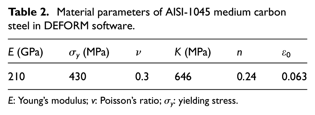
E: Young’s modulus; v: Poisson’s ratio; σy: yielding stress.
Experimental device and mold design
The main experimental device used in this study was the SD1-160 servo press, which is depicted in Figure 3. This device was used to process the U-shaped sheet metal. To determine the difference between the simulated and actual processing of the U-shaped sheet metal and to reduce the time required for completing finite-element analysis, the one-half symmetrical model was used in finite-element analysis in this study. Therefore, the U-shaped sheet metal was cut in half by using the Excetek NP400L wire-cutting electrical discharge machining system. The springback of the U-shaped sheet metal was measured using the Keyence VHX-5000 optical microscope. The coordinates of the corners of the U-shaped sheet metal were measured using the three-dimensional coordinate measurement machine. This machine was used because the corners were rounded and their coordinates were difficult to measure. After the U-shaped sheet metal was processed, the Delta ultrasonic cleaner was used to clean it. Next, the TOP TECH automatic mounting press was used to mount the U-shaped sheet metal to increase the convenience of the subsequent grinding process. After the U-shaped sheet metal was mounted, the metal was grinded using the metallographic grinding and polishing machine. Finally, the precision diamond saw was used to cut the U-shaped sheet metal into the required dimensions.

SD1-160 servo press.
The servo press was used in conjunction with a mold to process the U-shaped sheet metal. SOLIDWORKS was used to draw the extrusion mold of the circular cup placed in the servo press (Figure 4). The length, width, and thickness of the adopted blank were 110, 50, and 1 mm, respectively. The punch angle (ψp) was 94°, and the punch filet was R2 mm. The angle (ψd) and the filet of the die was 94° and R3 mm, respectively. The mold material was SKD11. The one-half symmetrical model was used to reduce the time required to perform finite-element analysis. The dimensions of the one-half U-shaped sheet metal processing mold are displayed in Figure 5.

Extrusion mold of the circular cup placed in a servo press.

Dimensions of the one-half U-shaped sheet metal processing mold.
Processing experiment for the U-shaped sheet metal
Selection of the simulation parameters and setup of the experimental device for processing the U-shaped sheet metal
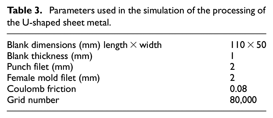
The DEFORM finite-element analysis software was used to simulate the processing of U-shaped sheet metal. First, two types of punch motion curves were created. The first type of simulated curve was the conventional punch motion curve (Case 0). In Case 0, the punch moved down for a distance of 29 mm and then moved upward. The simulated servo motor processed the U-shaped sheet metal. An elastoplastic body was used, and its grid number was 80,000. The Coulomb friction was considered in the simulation, and its value was 0.08. The parameters adopted in the simulation of the processing of the U-shaped sheet metal are presented in Table 3. The punch motion curves for the processing was simulated. The downward movement of the punch is displayed in Figure 6, and the upward movement of the punch and the release of stress by it are illustrated in Figure 7.
Parameters used in the simulation of the processing of the U-shaped sheet metal.

Stress distribution during the downward movement of the punch in the metal processing.

Stress distribution during the upward movement of the punch and the release of stress.
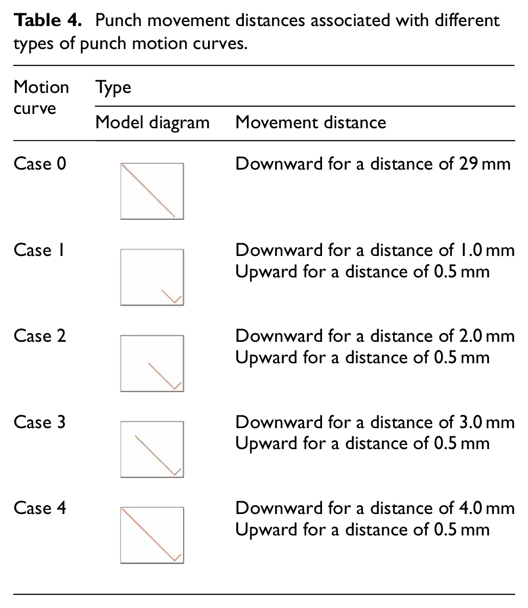
The changes in different punch motion curves were used as a basis for performing processing analysis. Four punch motion curves, one each for Cases 1, 2, 3, and 4, were constructed. Figure 8 and Table 4 show the differences in punch movement distance among the cases. The relationships among the load–stroke characteristics, stress, and strain of the U-shaped sheet metal were analyzed. The blank thickness was 1 mm. Because the friction coefficient (Coulomb friction) was difficult to measure during the forming process, the force–displacement curve of the simulation was compared with that of the experiment. Subsequently, the friction coefficient for the simulation was so that the force–displacement curve approximated the experimental curve. The friction coefficient that yielded simulated results close to the experimental results was obtained. The Coulomb friction was set to 0.08.

Punch motion curves for (a) Case 0, (b) Case 1, (c) Case 2, (d) Case 3, and (e) Case 4.
Punch movement distances associated with different types of punch motion curves.
Comparison of the simulated and actual processing of the U-shaped sheet metal
This chapter used the punch motion curves obtained for Cases 0 and 3 in the processing of the U-shaped sheet metal. The products produced using the punch motion curves for Cases 0 and 3 are displayed in Figures 9 and 10, respectively. The values simulated using DEFORM were compared with the corresponding experimental values. The experimental and simulated load–stroke diagram, profile, and springback of the U-shaped sheet metal were compared.

Finished product produced using the punch motion curve for Case 0.

Finished product produced using the punch motion curve for Case 3.
Load–stroke diagram of the U-shaped sheet metal after processing
The simulated and actual load–stroke diagrams of the U-shaped sheet metal for Cases 0 and 3 were compared. The load–stroke diagram for the conventional punch motion curve (Case 0) is depicted in Figure 11(a), and the load–stroke diagram for the punch motion curve corresponding to Case 3 is depicted in Figure 11(b). The punch movement distance exhibited higher variations before 2.5 mm than after 2.5 mm. For Cases 0 and 3, when the punch movement distances were 2.5–29 mm and 7.5–29 mm, respectively, the trends were similar, and the error was within the acceptable engineering limit.

Load–stroke diagram of the U-shaped sheet metal for (a) Case 0 and (b) Case 3.
Profile and springback of the U-shaped sheet metal after processing
The simulated and actual profile of the U-shaped sheet metal were compared. The simulated results were obtained using the DEFORM software. A wire-cutting electrical discharge machining system was used to cut the finished U-shaped sheet metal in half to observe its profile. The experimental results for Cases 0 and 3 are presented in Figure 12. An optical microscope, a laser displacement meter, and an image measurement instrument were used to obtain the profile of the U-shaped sheet metal experimentally. The simulated and experimental profiles of the U-shaped sheet metal for Case 0 are depicted in Figure 13(a). After springback, the difference in profile was not large, and errors occurred at the corners. Figure 13(b) displays a comparison of the simulated and experimental profiles of the U-shaped sheet metal for Case 3. After springback, the difference in profiles was not large. The simulated springback at the end of the sheet metal was larger and caused the sheet metal to bend upward.
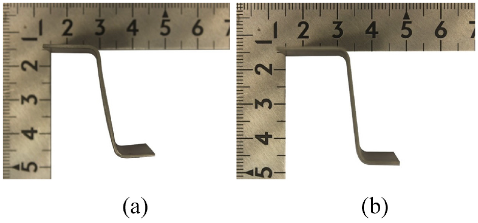
Experimental profile of the U-shaped sheet metal for (a) Case 0 and (b) Case 3.

Comparison of the simulated and experimental profiles of the U-shaped sheet metal for (a) Case 0 and (b) Case 3.
Parameter analysis for the processing of the U-shaped sheet metal
Effect of punch motion on the processing of the U-shaped sheet metal
This study analyzed the effect of the punch motion on the processing of the U-shaped sheet metal. The relationships between the load–stroke diagram, stress, and strain associated with the processing of the U-shaped sheet metal at a punch movement distance of 29 mm were investigated.
Load–stroke diagram of the U-shaped sheet metal
The effect of the punch motion on the load–stroke diagram of the U-shaped sheet metal was investigated (Figure 14). The results indicated that when the punch moved upward and released stress, the blank stress was immediately released. The smallest force was associated with the punch motion curve for Case 1 because the punch was released frequently in this case. In Case 4, the cyclic frequency of the punch when it moved 4 mm downwards was considered. The movement distance for Case 4 was long, which caused high levels of strain and hardening. Regarding the cyclic frequency of the punch in Case 2, the force required was larger, which caused the material to become harder and more brittle. In Case 1, the levels of strain and hardening were low because the punch movement distance was short and the cyclic frequency was high. The differences between the maximum forces associated with different punch motion curves are presented in Table 5. The results indicated that Case 1 exhibited the maximum difference in the percentage of load (up to 45.62%) from Case 0. Therefore, when the downward distance of the punch motion decreased, the maximum load acting on the product also decreased. Overall, the proposed punch motion curves (Cases 1–4) required less force than the conventional punch motion curve (Case 0).

Load–stroke diagram of the U-shaped sheet metal for (a) Case 1, (b) Case 2, and (c) Case 4.
Differences between the maximum loads associated with different types of punch motion curves.

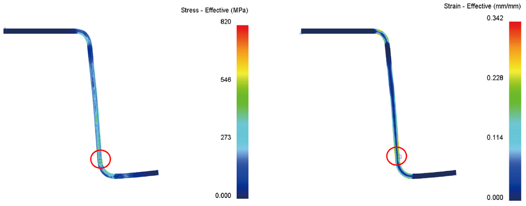
Equivalent stress and strain distribution of the U-shaped sheet metal
The stress and strain of the U-shaped sheet metal in different cases were investigated. The highest stress of the U-shaped sheet metal was observed in Case 0 (Figure 15). The equivalent stress and strain distributions for Cases 1–4 are displayed in Figures 16 to 19, respectively. When the punch moved upward in Cases 1–4, stress was released effectively. The simulated results indicated that the stress and strain were smaller in Cases 1–4 than in Case 0. The maximum stress and strain occurred at the bend of the U-shaped sheet (marked by a red circle). Table 6 lists the differences between the equivalent stress and strain values associated with the various motion curves. Compared with the values for Case 0, the stress and strain values obtained for Case 1 exhibited the largest differences. The stress and strain differed by 1.57% and 7.97%, respectively. These results indicate that decreasing the downward distance of the punch motion may reduce the stress and strain on U-shaped sheet metals. Accordingly, the downward distance of 1.0 mm used in Case 1 can induced the smallest punch load, stress and stress than the other Cases.

Equivalent stress and strain distribution of the U-shaped sheet metal in Case 0.

Equivalent stress and strain distribution of the U-shaped sheet metal in Case 1.
Equivalent stress and strain distribution of the U-shaped sheet metal in Case 2.

Equivalent stress and strain distribution of the U-shaped sheet metal in Case 3.

Equivalent stress and strain distribution of the U-shaped sheet metal in Case 4.
Equivalent stress and strain values associated with various motion curves and differences from those in Case 0.

Effect of the mold angle on the processing of the U-shaped sheet metal
The effect of the mold angle (ψd) on the processing of the U-shaped sheet metal was examined through simulations. In these simulations, five mold angles, namely 90°, 92°, 96°, 98°, and 100°, were considered for Cases 0–4; the Coulomb friction was 0.08; and the punch movement distance was 29 mm.
Relationship between the mold angle and the springback of the U-shaped sheet metal
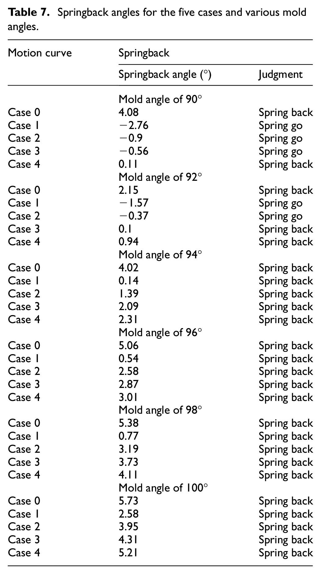
Figure 20 shows the U-shaped sheet metal before and after springback with mold angles of 90°, 92°, 94°, 96°, 98°, and 100°. This figure indicates that during the processing of the U-shaped sheet metal, some mold angles caused spring-go after springback. Therefore, the springback angles in Cases 0–4 were examined under the aforementioned mold angles to determine the threshold values for spring-go or springback to occur. Table 7 present the springback angles in Cases 0–4 under mold angles of 90°, 92°, 94°, 96°, 98°, and 100°, respectively. Figure 21 depicts the variations in the springback angle with the mold angle for each case. The punch movement distances for Cases 1–4 differed by 0.5, 1.5, 2.5, and 3.5 mm, respectively, from that for Case 0.

Comparison of the U-shaped sheet metal in Cases 0–4 before and after springback under a mold angle of (a) 90° (b) 92° (c) 94° (d) 96° (e) 98°, and (f) 100°.
Springback angles for the five cases and various mold angles.

Variations in the mold angle with the springback angle in different cases.
The smallest punch movement distance was observed in Case 1. Therefore, considerable stress was released and relatively low springback occurred in Case 1. In addition, spring-go occurred when the mold angle was 90° or 92° and it means that the parameter of mold angle is designed to limit smaller than 94° as the Case 1 is applied. Therefore, the optimal precision and formability were achieved in Case 1 (with the smallest punch movement distance) when the mold angle was smaller than 94°. For all of Case 1 shown in Table 7, the smallest absolute value of spingback angle is shown is 0.14 with the mold angle of 94°.
In Case 2, the optimal precision and formability occurred when the mold angle was 92.5°. In Case 3, the optimal precision and formability occurred when the mold angle was 92°. The punch movement distance in Case 4 was longer than that in Case 1. Consequently, the U-shaped sheet metal exhibited springback at every mold angle in Case 4. Therefore, when the punch movement distance was shorter, the springback reduced considerably, and the product had the expected precision. Case 0 used fixed punch movement. Therefore, large springback was observed in this case with every mold angle. Consequently, achieving the required precision was difficult in Case 0.
The relationship between mold angle and the equivalent stress of U-shaped sheet metal
Table 8 present the equivalent stress values obtained in different cases under mold angles (ψd) of 92°, 94°, 96°, 98°, and 100°, respectively. Figure 22 displays the variations in the equivalent stress with the mold angles in different cases. This figure indicates that a higher mold angle resulted in a smaller equivalent stress. The smallest equivalent stress was observed in Case 1 because the punch movement distance was the smallest in this case. The results is consistent with the conclusion of 4.1.2 meaning that Case 1 can induced the smallest punch load, stress and stress than the other Cases.
Equivalent stress values in the five cases with various mold angles.


Variations in the equivalent stress with the mold angle in different cases.
The highest equivalent stress was observed in Case 0 for each mold angle. This is because only a single fixed punch movement occurred in this case, and stress could not be released during processing. The punch movement distance in Case 0 differed from those in Cases 2–4 by 1.5, 2.5, and 3.5 mm, respectively. The average equivalent stress was between the equivalent stress in Cases 1 and 0. The largest difference between the equivalent stresses in different cases was achieved to 15 MPa when the mold angle was 94°. However, the smallest difference of the equivalent stresses for the mold angle of 98° and 100° was only 7 MPa. Therefore, a larger mold angle reduced the differences between the equivalent stresses in different cases.
Conclusion
Punch motion curves can be applied in metal forming with servo press to reduce the springback for sheet metal. By controlling the cyclic frequency of the punch, the forming stress of the sheet material can be reduced and the metal forming rate increased. With regard to the springback of U-shaped sheet metal after processing, the following conclusions were obtained in this study:
The methods used in this study can be applied in the analysis of the springback of U-shaped sheet metal after processing. The analysis results of this study are within the engineering error.
The simulated and experimental profiles of the U-shaped sheet metal agreed well. Thus, the simulation method adopted in this study has high precision and accuracy.
During the processing of U-shaped sheet metal, this study discovered that products processed using the proposed punch motion curves (Cases 1–4) required smaller forces than those processed using the conventional punch motion curve (Case 0).
In Case 1, considerable stress was released because the punch movement distance was short. Moreover, the highest springback reduction was achieved in this case. The aforementioned results proved that the cyclic frequency of the punch motion curve affected the forming precision and formability of metals. In addition, the number of molding processes can be reduced to increase production efficiency.
The shortest punch movement distance was that in Case 1. Therefore, in this case, considerable stress was released, and low springback occurred. In addition, when the mold angle was smaller than 94°, spring-go occurred. Moreover, when the punch movement distance decreased, springback considerably decreased, and the product was formed with the expected precision.
Footnotes
Handling Editor: Chenhui Liang
Declaration of conflicting interests
The author(s) declared no potential conflicts of interest with respect to the research, authorship, and/or publication of this article.
Funding
The author(s) disclosed receipt of the following financial support for the research, authorship, and/or publication of this article: This research was funded by Ministry of Science and Technology in Taiwan, grant number MOST 110-2221-E-167-021.