
Abstract
At present, large and cumbersome gravity sedimentation separators are generally used in the separation of liquid and gas in the wellbore during emergency blowout or circulating degassing in drilling, and innovation and improvement are urgently needed. In this paper, CFX commercial simulation software is used to analyze the cut-in cyclone separator, and the axial inlet type cyclone separator with different length ratios of cylinder-cone section in swirling flow section under different flow channel structures, and carried out indoor simulation and field test verification. The results show that the axial inlet type cyclone separator is more suitable for gas-liquid separation than the cut-in cyclone separator, and the separation can be well improved by increasing the length-diameter ratio of the cyclone section under the cut-in cyclone separator structure. Finally, the experimental separation efficiency reached 99%, and the field test separation efficiency reached more than 98%. This greatly improves the separation efficiency of liquid and gas during the drilling process, and also plays a certain role in promoting the separation of gas and liquid in the entire oil and gas industry.
Introduction
With the rapid development of the oil, natural gas, and chemical industries, the production scale of oil refining, natural gas, and chemical enterprises has gradually expanded, which has put forward higher requirements for the safety, stability, and convenience of production equipment. When emergency blowout or degassing is required in the drilling process, the liquid and gas from blowout or circulation in the wellbore must be separated, so as to better maintain the normal drilling work and a series of production treatments.
At present, in the domestic oil and gas industry, the gravity sedimentation type is commonly used for oil testing gas-liquid separators and gas-liquid separators in gas transmission stations. This equipment is bulkyand has an unsatisfactory separation effect. Compared with the traditional gravity sedimentation separator, the cyclone separator is smaller in volume, easy to disassemble and assemble, and has no excessive restrictions on gas-liquid mixtures of different processing volumes, which can solve the difficult problems of existing equipment very well. So far, a relatively complete theory and design method have been established for cyclone separators for gas-solid or liquid-solid separation, and many related practical applications and literature analysis have already appeared. Any exact theory can explain the complex flow mechanism of the gas-liquid two-phase flow, and a reliable mathematical model has not been established to accurately explain and predict the characteristics of the gas-liquid two-phase flow field. The application of separation is still very few, and the gas-liquid separation field applied in the oil and gas industry lacks a mature, high-efficiency and simple-structured gas-liquid separator.1–6
Currently, many scholars have done a lot of research on gas-liquid cyclone separators. Marek Wasilewski and Brar 7 analyzed and evaluated the effect of the inlet pipe on the separation efficiency and pressure drop of the cyclone by the CFD method; Khairy Elsayed and Lacor et al., 8 The cyclone separator was simulated to study the effect of the cyclone inlet size on the performance and flow pattern of the cyclone separator; Osama Hamdy et al., 9 conducted a numerical study on the standard cyclone, and gradually changed the cone length and cone angle to verify It is concluded that the cone length and cone angle have a significant impact on the internal flow pattern and separation efficiency of the cyclone; WI Mazyan et al., 5 studied through experiments that adding a tangential cavity can further improve the separation efficiency of particles, especially for small particles. Separation efficiency, and filtration traces for large particles. At the same time, scholars from various countries have carried out a lot of research on the guide vane and separation performance of this separator, and found that the arc guide vane has a strong swirl effect, a small pressure drop, and the best separation effect 10 ; Umeny et al., 11 First proposed an axial inlet type cyclone separator, which is to realize the separation by rotating the multiphase flow through the guide vanes fixed at the multiphase flow inlet of the cyclone. Compared with the cut-in cyclone separator, this kind of separator is smaller in size and more compact in structure, and the multiphase flow inlet is in the same direction as the gas phase outlet, the direction of the gas flow is not changed, there is no outer cyclone, only the inner cyclone, so the pressure drop is small; Dickson et al., 12 found that different length ratios of cylinder-cone section in swirling flow section has an important influence on the separation efficiency and performance of the axial inlet type cyclone separator, and the aspect ratio in the cyclone section is 2.4, the separation efficiency and performance of the separator are the best; Wang Luping et al., 13 verified that changing the guide fluid to a better streamlined cone or spindle structure can effectively avoid the pressure loss caused by the rapid change of speed.
In order to design a cyclone separator structure suitable for gas-liquid separation, and design a corresponding gas-liquid separator with high separation efficiency for emergency blowout or cyclic degassing during drilling, this paper uses classical common separator structures such as cyclone separator, axial inlet type cyclone separator, helical separator, and split-flow baffle separator are the design basis, and the above research is used as the theoretical basis, combined with the practical experience accumulated in engineering practice and in to improve the problems found in the optimization process, the structure of the above four kinds of separators was optimized and improved, and a variety of new separators with different structural characteristics were designed. The influence of the change of the flow field in the separator and the separation effect.14–20
In this paper, the CFX software is used to establish the simulation model of the separator of each structure. Through the simulation comparison, a new type of separator with a structure is selected. This separator is an inlet type cyclone separator, and its barrel flow channel structure is a spindle-shaped horizontal. Because the spindle-shaped horizontal flow channel has a better streamline, it can effectively avoid the pressure loss caused by the rapid change of speed, and improve the separation efficiency, especially the separation efficiency of fine discrete phases, and the filtration traces of large discrete phases. At the same time, through the research and analysis of the different length ratios of cylinder-cone section in swirling flow section under this structure, the length ratio of the best separation efficiency is obtained, which also verifies that it is consistent with the research results of Dickson et al. 12 Through laboratory experiments and field experiments, it is verified that the new cyclone separator can not only perform gas-liquid separation well, but also has excellent effect on the three-phase separation of gas, solid, and liquid, and the separation efficiency can reach 99%. The cyclone separator fills the gap of gas-liquid separation in the domestic oil and gas industry to a certain extent, and has a certain role in promoting the gas-liquid separation in the domestic oil and gas industry.
Improved design of gas-liquid cyclone separator
Structural optimization
Cyclone separators use the mass difference of the phase state and separate by inertia and cyclone. Its working principle is as follows: The original multiphase flow enters the separator through the multiphase flow inlet, enters into the spiral guide groove channel at a certain initial speed, and the denser heavy phase flows along the wall to the underflow outlet under the action of inertia, escape through the liquid phase outlet under the action of the wall and the cone; The lighter phase of lower density tends to accumulate toward the interior of the separator, and escape through the overflow pipe at the center to achieve separation.
In order to design a cyclone separator suitable for gas-liquid separation and maximize its separation efficiency and performance, based on the conclusions in the literature, 8 this paper makes the following improvements:
Model 1
According to the research results of Osama Hamdy et al.’s literature 9 and Larsson’s literature, 21 the cone length and inlet structure of the cyclone separator have a significant effect on the internal flow field and separation effect. Therefore, based on the existing gas-liquid cyclone separator, this paper designs a cut-in cyclone separator, and conducts the simulation of gas-liquid separation with different cone lengths. The design structure of Model 1 is shown in Figure 1. The main feature of this structure is that the multiphase flow inlet of the separator adopts a structure of three-dimensional spiral feed pipe.
Schematic diagram of model 1 structure: (a) Model 1.1 and (b) Model 1.2.
Figure 1 is a schematic diagram of the three-dimensional structure of model 1.1 and model 1.2 of the cut-in cyclone separator. Their parameter changes are the length of the cone segment, and their structural parameters are shown in Table 1.
Model 1 structural parameters.

Model 2
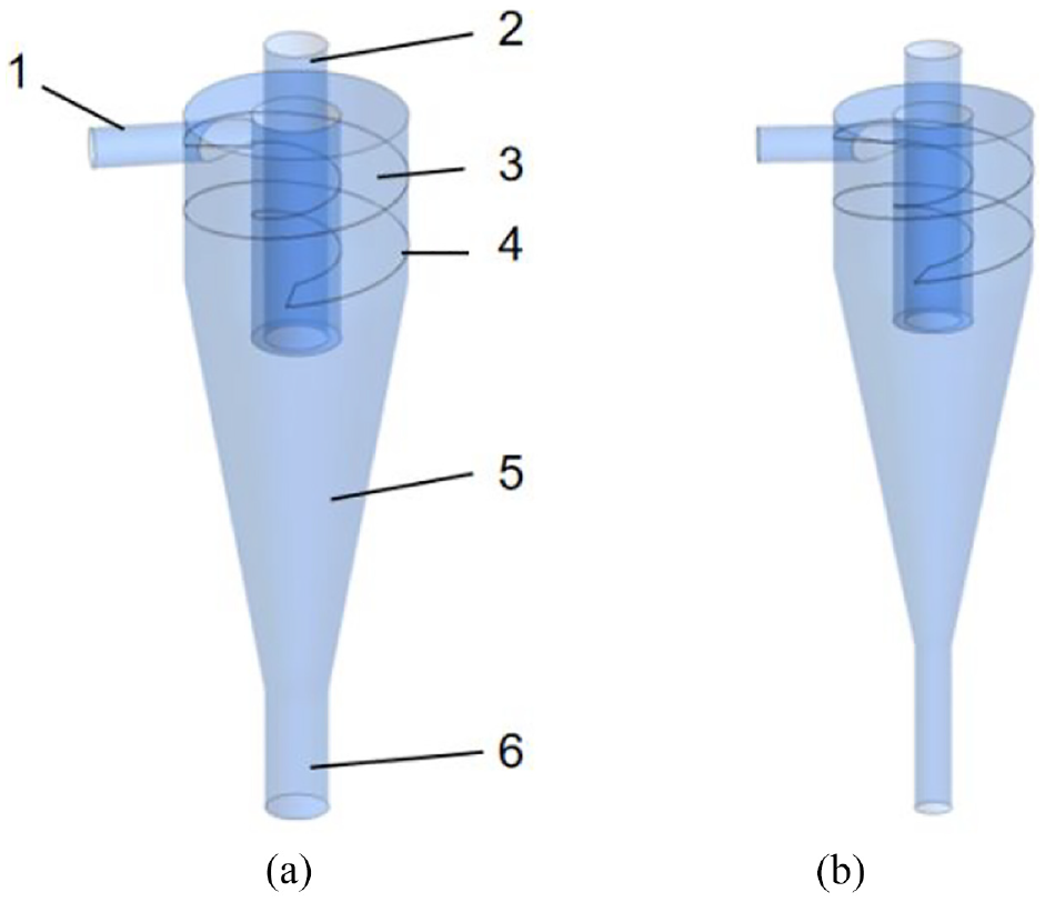
According to the research results of literatures,10–12 the axial inlet type cyclone separator is more suitable for the separation of gas-liquid two-phase. Based on the above research as the theoretical basis, an axial inlet cyclone separator was designed, and two kinds of cylinder-cone length ratio models were simulated and studied respectively, the two length ratios are 1.3 and 2.4, respectively, and the specific structure is shown in Figure 4. The main feature of this structure is that arc shaped-guide vane is used at the inlet of the multiphase flow to replace the helical guide groove in model 1.1, and a splitter baffle is added at the entrance of the gas phase outlet, and the swirling flow section consists of a cylinder section and a cone section.
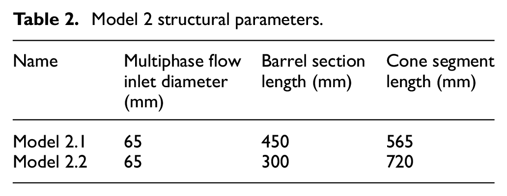
Figure 2 is a schematic diagram of the three-dimensional structure of model 2.1 and model 2.2 of the axial inlet type cyclone separator, their parameters vary in the cylinder-cone length ratio, and their structural parameters are shown in Table 2.

Schematic diagram of model 2 structure: (a) Model 2.1 and (b) Model 2.2.
Model 2 structural parameters.
Model 3
According to the research results of literatures,5,13 the swirl section cylinder is further improved into a better streamlined cone or structure of spindle-shaped, which can effectively avoid pressure loss caused by rapid changes in speed, thus improving the separation efficiency, especially for fine particles and filtration traces of large particles. Therefore, on the basis of Model 2, and other parameters remain unchanged, adjust the structure of the swirling flow section and design an axial inlet type cyclone separator with a structure of spindle-shaped horizontal flow channel. The simulation studies of three different length ratios of cylinder-cone section in swirling flow section were carried out respectively. The length ratios were 1.3, 1.8, and 2.4, and the specific structure is shown in Figure 3.

Schematic diagram of model 3 structure: (a) Model 3.1, (b) Model 3.2 and (c) Model 3.3.
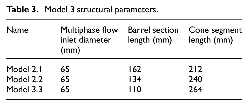
The main feature of this structure is that the structure of the separator is changed, and the arc-shaped-guide vane is used at the inlet of the multiphase flow to replace the helical guide groove in model 1.1, and uniformly adopt the structure of spindle-shaped horizontal flow channel and arc shaped-guide vane. Due to the use of a structure of spindle-shaped horizontal flow channel, the structure of the entire swirling flow section becomes more compact, Therefore, the splitter baffle at the inlet of the gas phase outlet is eliminated, and the swirling flow section consists of a cylinder section and a cone section. The structural parameters are shown in Table 3.
Model 3 structural parameters.
Simulation analysis and results discussion
Simulation analysis
Model establishment and mesh independence verification
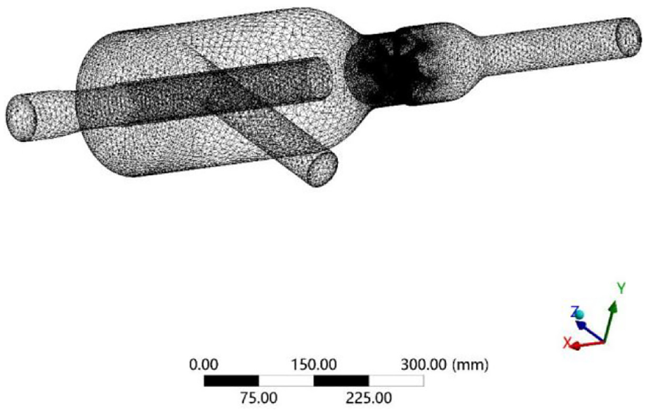
The inlet of the traditional cyclone separator is a cut-in separation chamber, due to the structure of the separator itself. The part whose entrance is cut into the cavity forms a tangential structure with the circular cavity. After the flow channel is extracted, the tangent part will cause the grid quality to be unsatisfactory when the structural grid is divided in the pre-processing, and the local grid quality is not ideal. It is recommended to use an unstructured mesh (tetrahedral mesh) to analyze the separator mesh. Taking model 1.1 as an example, through the grid independence verification of six different numbers of grids in the range of 400,000–870,000. The results are shown in Figure 4, which shows that when the number of grids reaches 790,000, the further increase in the number of grids has little effect on the calculation accuracy and will increase the calculation cost. Take the overall pressure value of the separation blade, the particle separation efficiency value, and the pressure velocity value at a fixed point in the cavity as the reference result. The difference between the results is within 5%, and the grid meets the engineering requirements. Therefore, the number of meshes selected in this paper is 790,000, and other separator models are also meshed with the same density.
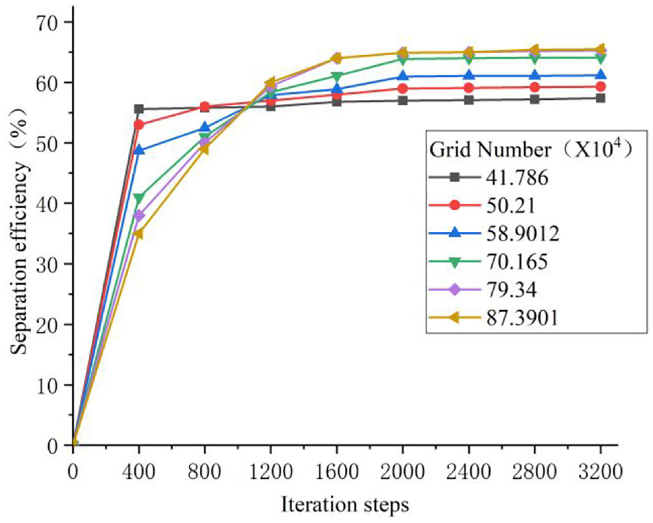
Grid Independence Verification.
There is a very thin fluid layer on the wall of the separator, and its velocity gradient is extremely large. If the wall function is used for simulation, the dimensionless distance y+ of the nodes in the layer needs to be obtained to meet the requirements. Considering the limited computer hardware conditions, take an appropriate y + value. Use the Viscous Grid Spacing Calculator to get the first boundary layer grid thickness. The scale factor is 1.2 and the number of boundary layers is 10. The mesh division is shown in Figures 5 and 6.
Grid diagram.

Local Grid diagram.
Turbulence model and preprocessing
Aiming at the problem of strong turbulent flow field in the cyclone separator, the turbulence model selected here is the standard k-e turbulence model. The turbulence model takes into account the viscosity of the fluid, as well as the fluid viscosity. Due to the existence of resistance along the path, the loss along the path is bound to exist. Therefore, the Inviscid model should be used for the turbulent flow model without considering the fluid resistance, which has a small scope of application and is not satisfactory for solving complex flow fields.
The gas phase is assumed to be the continuous phase and the liquid phase is assumed to be discrete particles in the analysis. Therefore, the calculation of particle trajectories in this paper adopts the particle transport model. The model is based on Euler-Lagrange, which can well analyze the particle motion trajectory in the flow field, and intuitively obtain the position change of the particle in the whole space. The particle motion equation is shown in formula (1).
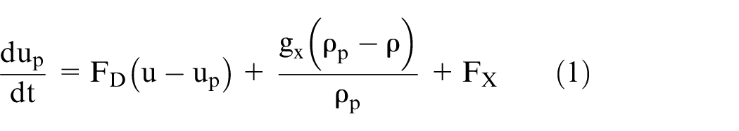
Where,
In the classical Euler-Lagrangian model, the collision between particles is not considered, so the collision process between particles is not considered in this paper, and only the particle collision process and the fragmentation process are considered. In gravitational gas-liquid separators and cyclone gas-liquid separators, the aerodynamic Weber number of droplets is generally not very large, so the effect of aerodynamic force generally does not cause droplets to break. The broken droplets inside the separator are mainly large droplets close to the cylinder wall, and they are mainly broken by vibration. Therefore, in the research of this paper, the TAB model is selected as the droplet breakup model. The equation for particle deformation with time is shown in formula (2).

Where,
Table 4 shows the simulation model parameters.
Simulation model parameters.

This paper uses Fluent steady-state solution. The default convergence residual of Fluent steady-state solution is 0.001, and the iterative residual meets the default residual value. The software will automatically stop the iterative operation. The general solution using this residual can meet the requirements, but the iterative convergence process of many flow fields is slow or periodically fluctuating. At this time, it is necessary to artificially add appropriate physical quantity monitoring to assist in judging the convergence of the flow field, such as fluctuations in velocity, pressure, and temperature at key points.
CFX analysis of Model 1 axial inlet type cyclone separator
Simulation and analysis of RSM turbulence model for the two different cone length ratios of cut-in cyclone separator by using CFX software. The research results are summarized as follows:
Flow field distribution
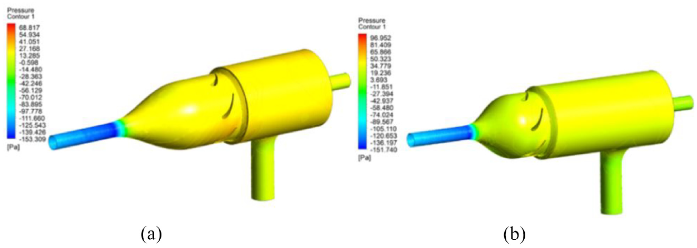
Figures 7 and 8 show the overall pressure and velocity distribution cloud diagrams of two models of cut-in cyclone separator with different cone length ratios when the inlet velocity is 19 m/s. It can be seen that the change trend of the pressure in the two separators is the same, and the static pressure inside the separator decreases from the inlet to the outlet, such as from the inlet of the separator to the junction of the cylinder and the cone, and then decreases as the diameter decreases in the cone.
Cloud diagram of pressure distribution of the structural model of the cut-in cyclone separator: (a) Model 1.1 and (b) Model 1.2.

Cloud diagram of central axis velocity distribution of the structural model of the cut-in cyclone separator: (a) Model 1.1 and (b) Model 1.2
After the discrete phase enters the separator, the velocity remains stable in the upper half of the cyclone, and the static pressure at the inlet of the multiphase flow and the upper part of the cylinder is the smallest. When the discrete phase flows from the upper half of the swirl slot to the lower half of the swirl slot, the velocity of the discrete phase increases to different degrees; In the cone section, the closer to the liquid phase outlet, the smaller the wall static pressure; At the outlet of the gas phase and the outlet of the liquid phase, the static pressure is the smallest.
Separation efficiency
An important indicator to measure the separation performance of a cyclone is its separation efficiency. The separation efficiency of the cyclone separator analyzed in this paper refers to the volume ratio of the amount of liquid removed to the amount of the original gas-liquid mixture.
Figure 9 shows the cloud diagram discrete phase velocity streamlines for two different cone-length ratio separator models. It can be seen that the diagram discrete phase velocity streamlines of the two separators are very close. After the discrete phase enters the separator, the revolution radius of the inlet section is large, and the linear velocity of the discrete phase reaches the maximum value at this stage, so the centrifugal force of the discrete phase at this stage is the maximum value.

Diagram of discrete phase velocity streamlines of the structural model of the cut-in cyclone separator: (a) Model 1.1 and (b) Model 1.2.
When the discrete phase enters the helical diversion groove, under the influence of steering loss and turbulence loss, 22 the linear velocity of the discrete phase decreases significantly. Most of the discrete phase is thrown to the wall of the swirling flow channel in the cone section, and then moves spirally downward along the wall, finally reaches the bottom of the separator and leaves from the liquid phase outlet; Due to the influence of the strong swirling flow inside the separator, part of the discrete phase is pushed to the inner wall of the center of the cone section by the pressure gradient force to make a spiral motion, and finally leaves the gas phase outlet; Part of the discrete phase is affected by the fluid resistance, 23 the movement direction shows strong randomness, and follows the gas to do internal rotation movement, leaving from the gas phase outlet, 24 thus reducing the separation efficiency. Finally, the proportion of discrete phases was detected in the gas phase and liquid phase, and the measured separation efficiency was 63.2% and 65%, respectively, and the separation efficiency was poor.
Summary
The above studies have proved that changing the separator cone length and cone angle has an effect on its internal flow pattern. However, it can be found from Figure 9 that the steering loss and turbulence loss caused by the cone section and the helical diversion groove of the cut-in cyclone separator will reduce the velocity of the discrete phase after it leaves the cone section. At the same time, the fluid resistance shows strong randomness, 23 which leads to the escape of part of the gas carrying part of the discrete phase from the gas outlet. The research results show that the cut in cyclone separator under such structural parameters is not suitable for gas-liquid separation, and the separation efficiency is only about 65%. Therefore, it is necessary to further improve the structure of separator to upgrade the separation efficiency.
CFX analysis of Model 2 axial inlet type cyclone separator
Simulation and analysis of RSM turbulence model for the two different length ratios of cylinder-cone section in swirling flow section of axial inlet type cyclone separator by using CFX software. Its findings are summarized as follows:
Flow field distribution
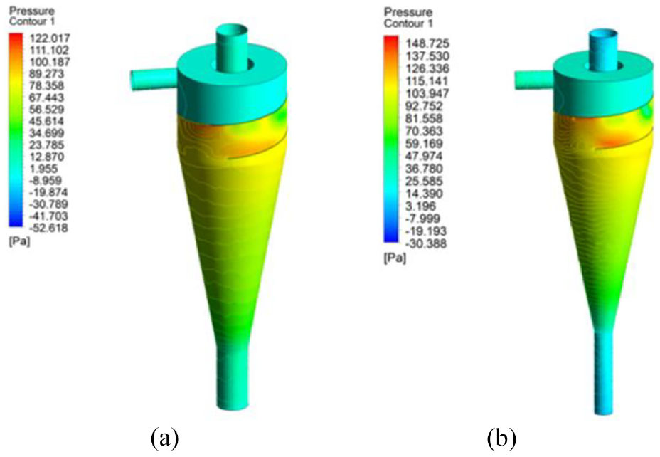
It can be seen from Figures 10 and 11 that the pressure distributions in the two separators are very similar, with only differences in value. It is mainly manifested in the lowest static pressure at the inlet of the separator, and at the cone section, as the diameter of the cone increases, the pressure increases. At the same time, at the position close to the guide vane, due to the increase of the fluid flow section, the static pressure also increases sharply; In addition, due to the increase of the particle revolution radius at the guide vane, the centrifugal force of the discrete phase increases, and the energy loss increases, so the linear velocity decreases sharply; At the junction of the cone section and the cylinder section, the static pressure reaches the maximum value.
Cloud diagram of pressure distribution of the structural model of the axial inlet type cyclone separator: (a) Model 2.1 and (b) Model 2.2

Cloud diagram of central axis velocity distribution of the structural model of the axial inlet type cyclone separator: (a) Model 2.1 and (b) Model 2.2.
After the fluid passes through the guide vane, the local resistance caused by the arc shaped-guide vane in inducing the discrete phase rotation is small, and the discrete phase velocity does not change significantly, so the static pressure of the swirling flow section of the cylinder remains almost unchanged.
Separation efficiency
As shown in Figure 12, the length ratios of cylinder-cone section in swirling flow section of the Model 2.1 is 1.3. The discrete phase enters the swirling flow section of the cone from the multiphase flow inlet, as the swirling flow section of the cone increases, the radial airflow decreases, and the axial velocity of the discrete phase also decreases. Under the influence of gravity, the trajectory of the discrete phase gathers to the lower side of the guide vane, so that after the discrete phase passes through the guide vane, the streamline shows a chaotic state and spreads to the swirling flow section of the cylinder. At this time, the discrete phase reaches the high pressure area of the cylinder, the axial velocity is low, and the discrete phase is subject to a large centrifugal force, which is not easy to escape from the gas phase outlet. However, due to the short distance between the guide vane and the splitter baffle, and the high velocity of the discrete phase, a small part of the discrete phase hits the splitter baffle and returns, eventually escaping from the gas phase outlet.
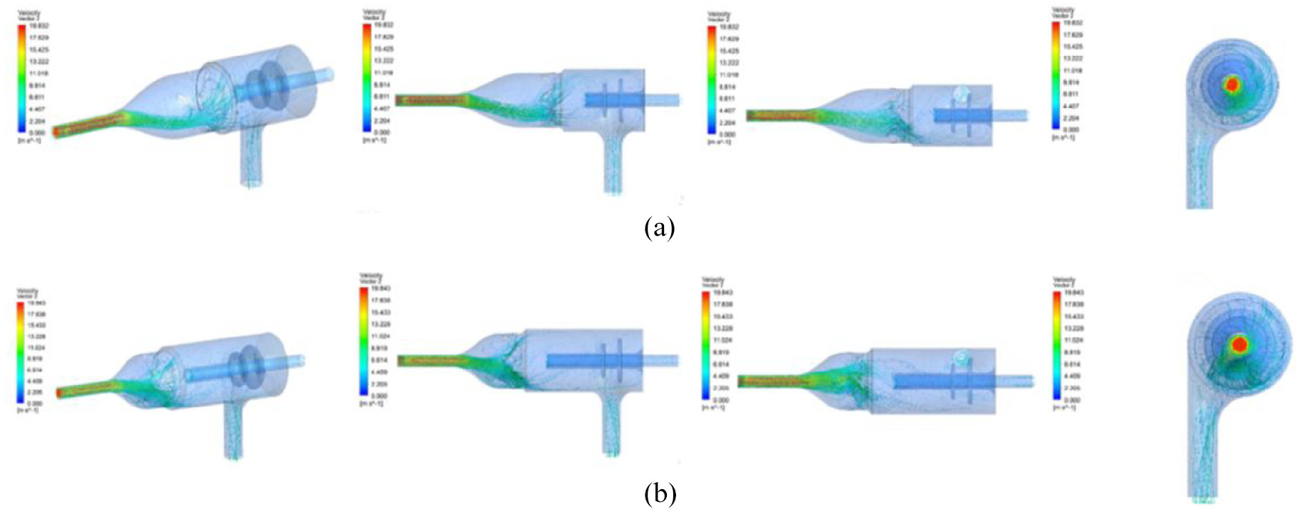
Diagram of discrete phase velocity streamlines of the structural model of the axial inlet type cyclone separator: (a) Model 2.1 and (b) Model 2.2.
As shown in Figure 12, the length ratios of cylinder-cone section in swirling flow section of Model 2.2 is 2.4. It can be seen that after the swirling flow section of the cone is shortened, the discrete phase is less affected by gravity and can reach the guide vanes in a more dispersed manner. And after passing through the guide vanes, the streamlines show a relatively regular spiral shape, which spreads to the swirling flow section of the cylinder; At the same time, the growth of the swirling flow section of the cylinder reduces the velocity of the discrete phase when it reaches the splitter baffle, and can not be affected by the impact of the splitter baffle and return, and the efficiency of the separator has been greatly improved. Finally, the proportion of discrete phases was detected in the gas and liquid phases, and the separation efficiencies of Model 2.1 and Model 2.2 were measured to be 83.6% and 90.2%, respectively.
Summary
The above studies have proved that increasing the length ratios of cylinder-cone section in swirling flow section of the separator has a positive effect on its internal flow pattern, and the separation efficiency is most significantly improved when the ratio is around 2.4. At the same time, the arc shaped-guide vane has lower pressure loss and stronger discrete phase capture efficiency. 13 However, it can be found from Figure 10 that in the axial inlet type cyclone separator, during the movement process of the discrete phase entering the cylindrical swirling flow section through the arc shaped-guide vane, during the movement process of the discrete phase entering the swirl section of the cylinder through the guide vanes, because the flow area of the discrete phase becomes larger, the axial velocity decreases, the movement trajectory is disordered, and the follow-up is strong, so there is a small part of the discrete phase escapes from the gas phase outlet, and the separation efficiency is reduced. The separation efficiency of model 2.2 and model 2.3 were finally measured to be 83.6% and 90.2%, respectively. The separation efficiency is about 20% higher than that of the cut-in cyclone separator, but it cannot meet the 98% separation efficiency requirement in actual production. Therefore, it is necessary to further optimize or improve the structure of the separator to improve the separation efficiency.
CFX analysis of Model 3 structure of spindle-shaped horizontal flow channel
Using CFX software to simulate and analyze the RSM turbulence model of the three different length ratios of cylinder-cone section in swirling flow section of axial inlet type cyclone separator with horizontal spindle flow channel structure. Its findings are summarized as follows:
Flow field distribution
Comparing Figure 13, the trend of pressure changes in the separators of models 3.1 and 3.2 is very close, but the pressures of model 3.3 and the previous two models are significantly different after the discrete phase passes through the guide vanes. The static pressure has reached a high value at the inlet of the multiphase flow, and reached the maximum value in the conical swirling flow section. This is due to the fact that after the discrete phase enters the conical swirling flow section, the revolution radius becomes larger and the centrifugal force increases.

The pressure distribution cloud diagram of the axial inlet type cyclone separator structure model with the structure of spindle-shaped horizontal flow channel: (a) Model 3.1, (b) Model 3.2 and (c) Model 3.3.
In the cone section, the velocity of the discrete phase is the smallest near the wall of the cone section due to the large energy loss; After passing through the guide vane, the static pressure value drops, and a low pressure area is formed in the swirling flow section of spindle-shaped cylinder, extending to the gas and liquid phase outlets. This is because the cylindrical swirling flow section of the spindle-shaped horizontal flow channel has a better streamline, and the discrete phase near the wall can be smoothly accelerated, so that the energy loss is reduced and the separation efficiency is improved.
When the length ratios of cylinder-cone section in swirling flow section is increased to 2.4, it can be seen from the model 3.3 in Figure 11 and the model 3.3 in Figure 14 that the overall static pressure value of the separator becomes smaller, and the static pressure reaches the maximum value at the conical swirling flow section. Different from the pressure distribution of models 3.1 and 3.2, there is no low pressure area formed at the cylindrical swirling flow section, but appears at the gas and liquid phase outlets. This is because the length ratios of cylinder-cone section in swirling flow section increases, the discrete phase is little affected by the strong internal swirling flow after passing through the guide vanes, the overall velocity does not change greatly, and escapes from the liquid phase outlet with a good state.

Cross-sectional velocity distribution cloud diagram of axial inlet type cyclone model with the structure of spindle-shaped horizontal flow channel: (a) Model 3.1, (b) Model 3.2 and (c) Model 3.3.
Separation efficiency
It can be seen from Figure 15 that the axial inlet type cyclone separator with the structure of spindle-shaped horizontal flow channel has a good movement trajectory of the discrete phase, and the movement trajectory of the discrete phase in the three separators is very close.

Discrete phase streamline cloud diagram of axial inlet type cyclone model with the structure of spindle-shaped horizontal flow channel: (a) Model 3.1, (b) Model 3.2 and (c) Model 3.3.
After the discrete phase passes through the guide vanes, the spindle-shaped horizontal flow channel has a better streamline structure, so that the discrete phase can maintain a gentle acceleration process in the cylindrical swirling flow section, and the discrete phase close to the wall is mainly subjected to outward centrifugal force. Therefore, an ordered helical trajectory can be formed to converge to the liquid phase outlet and escape. However, due to the different length ratios of cylinder-cone section in swirling flow section of the three separator models, the trajectories of the discrete phase streamlines in the cylindrical swirling flow section are also slightly different. As shown in Model 3.1, Model 3.2 and Model 3.3 in Figure 15, as the length ratios of cylinder-cone section in swirling flow section increases(Model 3.1 ratio is 1.3, model 3.2 ratio is 1.8, model 3.3 ratio is 2.4), the influence of the discrete phase by the strong internal swirling flow decreases, and the influence of steering loss and turbulence loss also decreases, 22 the discrete phase away from the wall can also be smoothly accelerated to form an orderly spiral, and the discrete phase close to the wall escapes at the liquid phase outlet. Finally, the proportion of discrete phases was detected in the gas and liquid phases, and the separation efficiencies of Model 3.1, Model 3.2 and Model 3.3 were measured to be 92.7.6%, 96.5%, and 99.3%, respectively.
Summary
The above studies have proved that increasing the length ratios of cylinder-cone section in swirling flow section of the separator has a positive effect on its internal flow pattern. When the ratio is around 2.4, the improvement of separation efficiency is the most significant; At the same time, the structure of spindle-shaped horizontal flow channel has better streamlines, which can make the discrete phase entering the cylindrical swirling flow section through the guide vanes, and after passing through the spindle-type flow channel, the speed and direction will not change sharply, avoiding the pressure loss. This spindle-shaped space can stabilize the internal flow field of the separator and form a strong rotation, and the discrete phase can better converge to the liquid phase outlet in the spindle-shaped space, so that the separation efficiency can be effectively improved. The final measured separation efficiencies of model 3.1, model 3.2 and model 3.3 were 92.7%, 96.5%, and 99.3%, respectively. Compared with the cut-in cyclone separator, the separation efficiency is improved by about 10%, and the model 3.3 can already meet the 98% separation efficiency requirement in actual production.
Indoor test and field application
Indoor simulation test
In order to test and optimize the separation effect of the axial inlet type cyclone separator for different densities of drilling fluids and different pressures. Now a set of scale model of the separator has been processed, which is shown in schematic Figure 16. First, 6 groups of gas-liquid separation tests with different inlet pressures were carried out, the test results are shown in Table 5:

Scale model of axial inlet type cyclone separator.
Axial inlet type cyclone separator model laboratory test data sheet.

Draw the curve as shown in Figure 17:

Separation efficiency curves of different intake pressures.
It can be seen from Figure 17 that within the working pressure range, wen the minimum inlet pressure is 0.3 MPa, the liquid phase separation efficiency reaches 93.2%; When the inlet pressure reaches the common working pressure value of 0.8 MPa, the liquid phase separation efficiency is as high as 98%. It can be seen that the higher the intake pressure, the higher the separation efficiency of the liquid phase, and the separation process and separation efficiency under different working pressures are very ideal. The separation efficiency obtained from the experiment and the simulation calculation results are within the error range, and the calculation error and experimental error factors in the numerical simulation are considered, and the simulation and experimental results are basically consistent.
In addition, in actual working conditions, solid impurities may exist in the gas entering the separator during emergency blowing or degassing. Therefore, a solid phase separation test was carried out by adding quartz sand, as shown in Figure 18:

Laboratory test of solid phase separation.
First, add quartz sand into the solid phase measuring cup, and set the air inlet pressure to 0.5 MPa. After the start of the test, the separator equipment worked well without any problems. Finally, there is no solid phase particle in the gas phase measuring cup, the solid phase separation effect is excellent, and the separation efficiency is as high as 100%, as shown in Figure 19:

Laboratory test results of solid phase separation.
Through the experiments of gas-liquid separation and solid-phase separation under different pressures on the scale model of the axial inlet type cyclone separator in the room. It is verified that the axial inlet type cyclone separator under this structure can well complete the gas-liquid separation under different pressures, the separation efficiency can reach 98%, and the separation effect is good. The test results are basically consistent with the simulation results. The solid phase separation test has verified that in actual working conditions, the solid impurities entering the axial-entry cyclone separator with natural gas can also be well separated by the separator, ensuring that there is no solid and liquid at the gas phase outlet. The separation efficiency reaches 99%, and the three-phase separation of solid, liquid and gas can be achieved to a certain extent.25,26
Field application
Experimental scheme
The test wells are Wei 204H34, and the axial inlet type cyclone separator system used is shown in Figure 20. Among them, the multiphase fluid passes through the separator, and the gas enters the gas phase outlet. The liquid and solid particles flow along the wall surface, flow out from the liquid phase outlet at the lower end, and enter the liquid collecting tank. An electromagnetic wave level gauge is installed on the upper part of the liquid collecting tank, and an electric regulating valve is installed at the lower outlet. The liquid level is monitored by the electromagnetic wave liquid level gauge, and the electric regulating valve is automatically controlled to maintain the liquid level inside the liquid collecting tank, forming a liquid seal to prevent the gas from escaping from the liquid outlet. Since no liquid was discharged from the gas phase outlet of the separator in the field test. Therefore, in this test, the liquid content of the natural gas entering the axial inlet type cyclone separator and the liquid content at the outlet of the liquid phase were tested to verify the separation efficiency of the separator. The liquid content of natural gas can be calculated according to the following formula (3); The separation efficiency of the separator can be reacted according to the liquid treatment efficiency of the separator, refer formula (4).27–29


PID diagram of a full set of axial inlet type cyclone separator system.
Where,
This test is carried out by the co-operation of the axial inlet type cyclone separator system and the closed burner. In order to further verify the separation effect of the axial inlet type cyclone separator, and during the natural gas blowout test, with the gradual discharge of the bottom layer liquid, the gas production at the wellhead can gradually increase and become stable. Therefore, this test is divided into the treatment stage of a single set of axial inlet type cyclone separator (small gas production stage) and the treatment stage of a full set of axial inlet type cyclone separators (normal emission stage). Intermittent use of the axial inlet type cyclone separator system for 6d, a total of about 35 h. Among them, the single set axial inlet type cyclone separator treatment stage (small gas production stage) emission test lasted for 4 days, and Select 2d of them to carry out the axial inlet type cyclone separator system test, and use the axial inlet type cyclone separator system intermittently for about 15 h; The normal emission stage lasted for 25 days, and 4 days were selected to carry out the axial inlet type cyclone separator system test, and the axial inlet type cyclone separator system was used intermittently for about 20 h. 30
Experimental process
The separation test of gas-liquid co-spray was carried out. In the initial stage, due to the low gas production of a single well, only a single set of inlet type cyclone separator was opened. The average gas treatment capacity of a single set of axial inlet type cyclone separator is 20 × 104 m3/d, the average liquid treatment efficiency is 98%; At this time, the liquid level of the liquid collecting tank of the entire separator system is accurately controlled, the closed burner burns normally, and no liquid is discharged from the gas outlet of the separator, and no gas escapes from the liquid outlet.31,32
During normal emission, the full set of inlet type cyclone separator system is turned on, the average gas treatment capacity is 40 × 104 m3/d, The average liquid treatment efficiency is 98.5%. and the average liquid treatment capacity is 6 × 10³ m3/d, the liquid treatment capacity is 6.05 × 10³ m3/d. At this time, the entire separator system works stably, the gas treatment capacity is increased, and the liquid treatment efficiency is improved. Accurate liquid level control of the liquid collecting tank, and the closed burner burns normally, no liquid is discharged from the gas outlet of the separator, and no gas escapes from the liquid outlet. The field measurement data is shown in Figure 21.33,34

The change curve diagram of the gas-liquid processing capacity of a single set of separators and the liquid treatment efficiency of a full set of separators during normal gas-liquid co-spraying.
Experimental conclusion
The test results show that the axial inlet type cyclone separator system has high separation efficiency, and has obvious advantages in space utilization and gas-liquid separation. The liquid level of the liquid collecting tank of the entire separation system is precisely controlled, and there is no liquid at the gas outlet, and no gas escapes from the liquid outlet. The statistical results of the separation efficiency of multiple field tests can reach 98% and above. It can meet the separation requirements of well site blowout prevention and drainage. On-site physical objects is shown in Figure 22.

On-site physical objects diagram of the axial inlet type cyclone separator system.
Conclusion
In this paper, the simulation experiment and research of the cut-in cyclone separator, the axial inlet type cyclone separator and their different length ratios of cylinder-cone section in swirling flow section under different structure of flow channel are carried out. The separator with the highest separation efficiency was selected, and laboratory experiments and field experiments were carried out, and the following conclusions were obtained:
Through the simulation experiment of the cut-in cyclone separator, changing its length of the cone segment, reducing the length of the cone section of the separator from 700 to 550 mm, and increasing the separation efficiency from 63.2% to 65%, the separation efficiency has little change and no obvious improvement, which proves that the cut-in cyclone separator is not suitable for gas-liquid separation, the separation efficiency has little change and no obvious improvement, which proves that the cut-in cyclone is not suitable for gas-liquid separation.
Compared with the cut-in cyclone separator, the experimental results show that the separation efficiency of the axial inlet type cyclone separator is above 83%; The axial inlet type cyclone separator with the structure of spindle-shaped horizontal flow channel has excellent gas-liquid separation efficiency compared with the general axial inlet type cyclone separator, and the separation efficiency is above 92%.
By increasing the length ratios of cylinder-cone section in swirling flow section of the separator from 1.3 to 2.4, the overall static pressure value in the separator is decreasing, and the separation efficiency is improving, the overall static pressure value in the separator is decreasing, the separation efficiency is improving, and the cylinder in the cyclone section is increasing. When the ratio of body length to cone length is 2.4, it reaches 99%, and when the ratio of the cylinder length to the cone length in the cyclone section is 2.4, it reaches 99%, that is, when the length ratios of cylinder-cone section in swirling flow section of the separator is 2.4, the separation efficiency is the best.
The field test shows that the maximum gas treatment capacity of a single set of inertial separators is 20 × 104 m3/d, and the liquid treatment capacity is 3 × 10³ m3/d; Use in parallel can further improve the separation efficiency, when used in parallel, the maximum gas treatment capacity is 40.7 × 10⁴ m3/d, and the liquid treatment capacity is 6.05 ×10³ m3/d.
Footnotes
Handling Editor: Chenhui Liang
Declaration of conflicting interests
The author(s) declared no potential conflicts of interest with respect to the research, authorship, and/or publication of this article.
Funding
The author(s) disclosed receipt of the following financial support for the research, authorship, and/or publication of this article: CNPC’s “14th Five-Year” forward-looking basic major scientific and technological project “Research on optimal and fast drilling technology for deep and ultra-deep wells” Subject 3 “Development of 70MPa automatic throttling system” (No.: 2021DJ4103).