
Abstract
For many years, wheeled manipulator (WM) becomes an effective solution in many aspects of our economics such that it assists to maintain the highly manufacturing production. In this work, the proposed design of motion controller for WM to handle an object is introduced. The hardware of this WM consists of two components, mobile platform and robotic manipulator. Our concept is to design the structure of differential drive for mobile base while the configuration of on-board manipulator is the parallelogram mechanism. Owing to this architecture, the system modelling of whole body is then established to identify related constraints. To ensure the sustainable movement, the system state is asymptotically stable according to Lyapunov candidate function. Both numerical simulation and practical experiment are validated in various test scenarios. With 20 demonstrations for each task, the proposed approach reaches to success rate over 90% of test cases which well-track the desired trajectory and precisely complete the robotic manipulation.
Keywords
Introduction
Across many applications, WM has demonstrated the feasibility and effectiveness in practice. However, it must be improved continuously to meet the challenges of complex tasks. Given any less structured scenario or dynamic environment, it requires the sensitive or cognitive abilities to perform actions correctly. For instance, investigators in Štibinger et al. 6 delivered an excellent solution from localization and picking to transportation on uneven terrain with different lighting conditions. The other challenges of WM are possibly the motion planning, group formation or stability control. Since the architecture of WM is redundant, there are several pros and cons such as flexible in harsh environment but difficult to generate the planning process due to the inverse kinematic troubles. In Zafar and Mohanta, 7 WM was classified into two sub-systems and managed two planners, that is, one for mobile base 8 and one for manipulator.9,10 The separate planning is better if the requirements of this system is soft real-time, less computation and single target. Reversely, manipulation planning for whole robot is always hard to check the motion constraints, potential collision, and globally optimal path.
Reaching to goal, cooperative formation is one of the main topics for multi-agent system. 11 In a case that path planning is completed in the configuration space, goal state must be mentioned in the same domain. A hierarchical approach of the cooperative spatial payload manipulation12,13 was launched to estimate collision-free trajectory in the formation of multi-robot system. It required virtual configuration of load to define a convex workspace as well as the decentralized model-predictive controller for each robot.
Precise tracking path and stability control are the typical challenges and should be guaranteed simultaneously, especially under the circumstance with complicated road conditions. There are many interferences of the interactive forces between robot and external environment. In Pankert and Hutter 14 and Li et al., 15 robotic awareness of working environment was firstly revealed to recognize and evaluate forces. Some constraints for mechanical stability and limitations of links were added to certify the smooth motion of whole body.
The contributions of this paper are to (i) launch the platform of wheeled manipulator comprising the differential drive (DDR) structure for mobile base, robotic arm with parallelogram mechanism, (ii) design the motion controller based on Lyapunov approach and (iii) exemplify the proposed method in both numerical simulations and experimental validations.
Literature review
In recent years, many variants of the WM structure have been developed successfully. Basically, it derives from the driving mechanism of base platform or the mounted manipulator. Mobile base could track the reference trajectory in freeway16–18 or rail while the configuration of robot arm should be serial or parallel articulation.
Generally, WM could be classified along with its applications and technical implementation. One of typical issues in driving WM is motion control and free-collision planning. There are various developments in both static and dynamic scenario. Secondly, many control strategies have been invested to enhance the autonomous performance of WM. 19 Thirdly, assisted-living technique or interactive communication with human is also an interesting subject. Table 1 summarizes the state-of-the-art for related studies.
Review of related researches in the field of mobile manipulator.
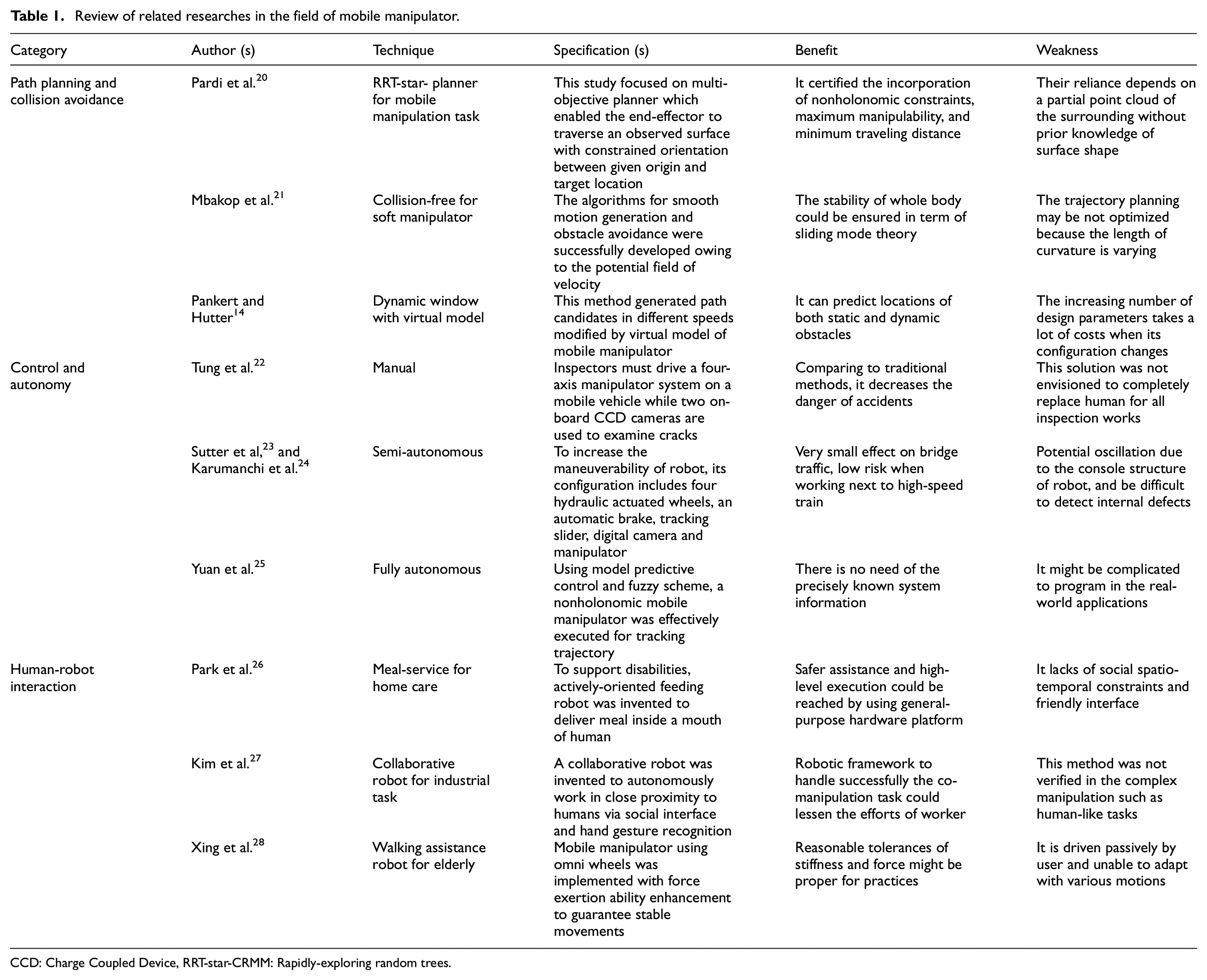
CCD: Charge Coupled Device, RRT-star-CRMM: Rapidly-exploring random trees.
Preliminaries
Mobile platform
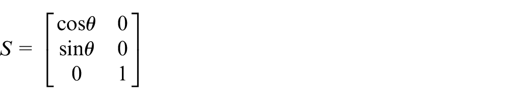
The DDR structure of mobile platform as Figure 1 consists of two driving wheels (side-by-side), two omnidirectional wheels (front-rear), one electrical cylinder and four linear sliders. With this design, robot could move flexibly and smoothly while the nonholonomic specifications are preserved. The tracking point C is placed in the center of mobile platform which is represented by
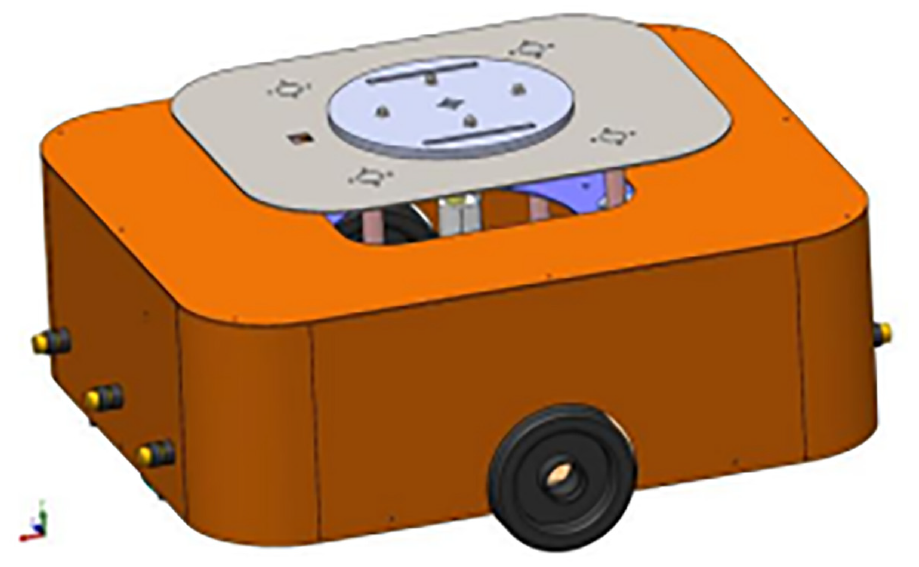
3D design of mobile platform.
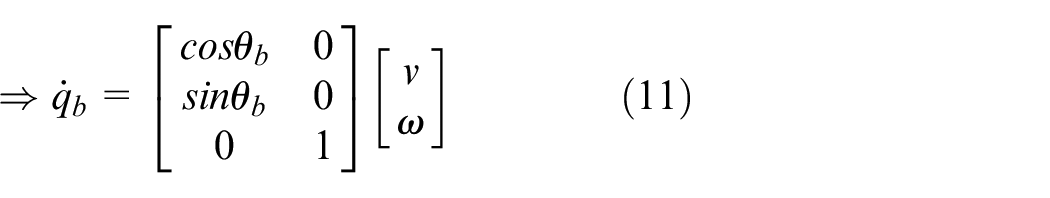
The motion of this mobile robot is described as

where
Hence, velocities of right wheel
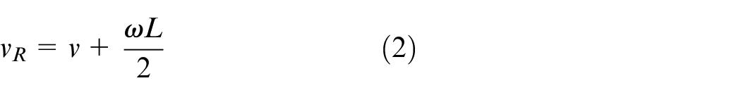
where
Gripper
In practice, there are many types of grippers used and classified by contact type and grasping principle. In this topic, a clamping-type gripper as Figure 2(a) combined with linear transformation is elected since it is easy to compute the traveling distance so that this gripper can pick up an object.
Theoretical modeling of dual-finger gripper (a) and grasping object (b).
With the task requirement of picking up an object (40 × 40 mm), this gripper has a minimum opening distance D between two fingers. Its distance is greater than 40 mm and the length of the gripper must also be greater than or equal to 40 mm. Moreover, when two fingers are in touch, the boundary values of both length and width must be satisfied as
For the analysis of grasping object model as Figure 2(b), a light layer of rubber which as the friction coefficient
where
For more details, the interactive forces at point D’ are synthesized as Figure 3(a).

In the xOy, it becomes
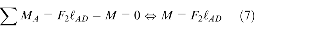
At point A, the driving moment is
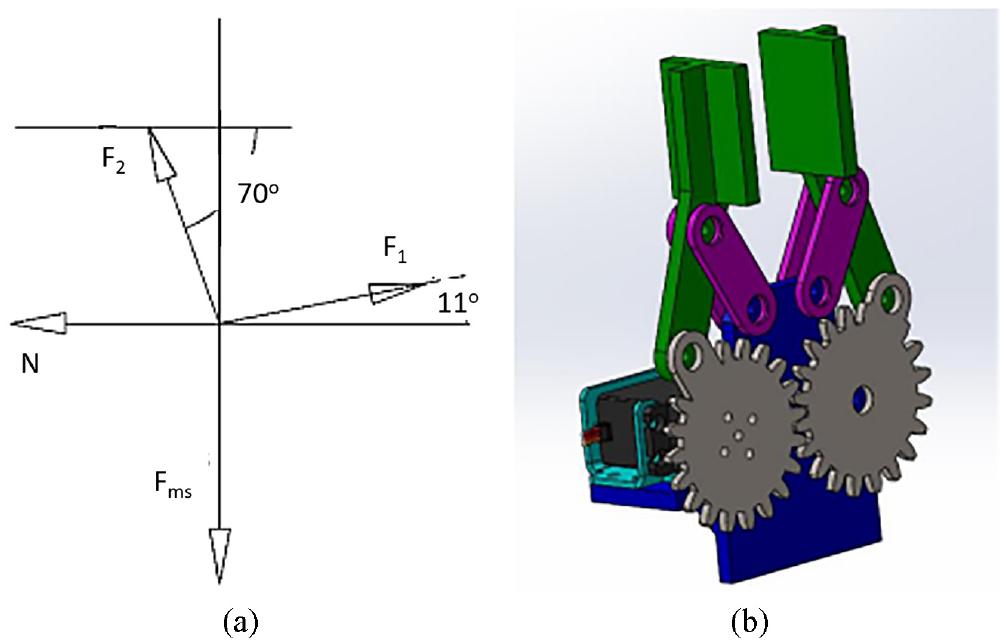
Analysis of the interactive forces at point D’ (a) and 3D design of the proposed gripper.
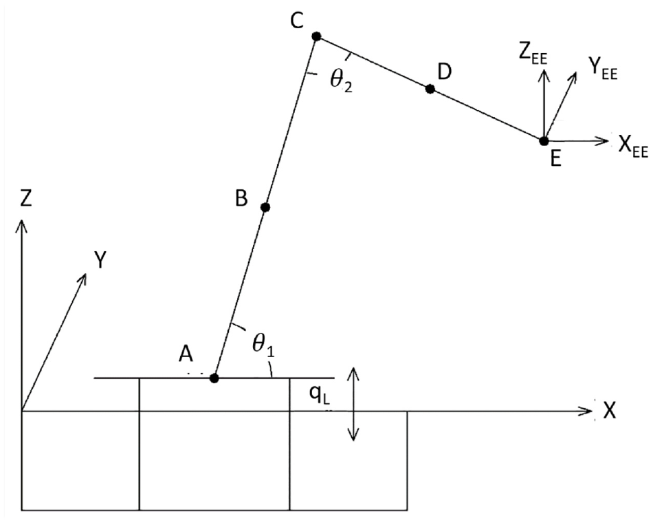
Manipulator and base
In this work, the proposed model for industrial manipulator is depicted as Figure 4. There are three links which the bottom one is base link. The lowest point of this manipulator in the workspace is horizontal with the base link. According to the x direction, the shortest distance from the motor shaft to the lowest limit of the manipulator is
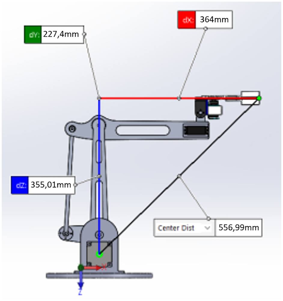
3D design of industrial manipulator.
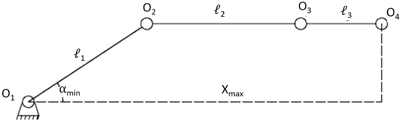
Evaluation of the farthest position for our manipulator.
To hold this system, it must satisfy

where
From equation (8), it means that the maximum reach of this manipulator occurs when second link is in a horizontal position as Figure 5. Presently, distance from O1 to location of gripper in the x axis is

System modeling
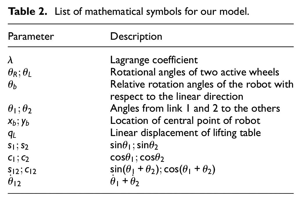
From the proposed design in mechanical framework, several mathematical symbols have been defined as Table 2. In the model of this robot, 30 the dynamic equation is

where
With
where
List of mathematical symbols for our model.
We get
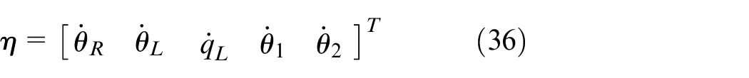
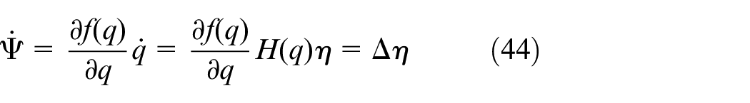
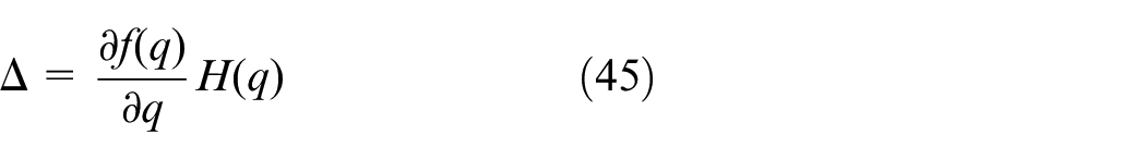
The first derivative of state variable is described as


where
The dynamic equation could be re-written as

where
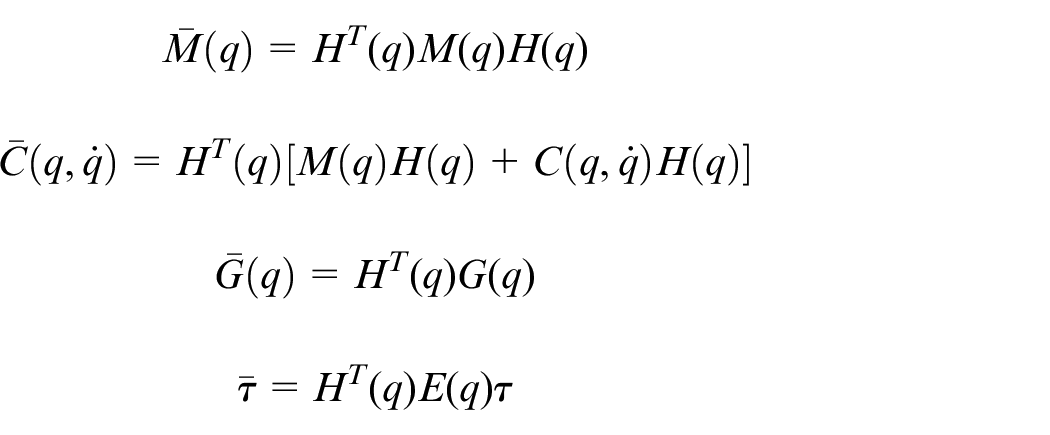
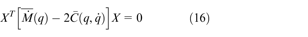
Assumption 1: The inertia matrix

Assumption 2: The symmetric relation in respect to its diagonal between inertia matrix
Assumption 3: The dynamic equation is linearized with the vector of uncertainties

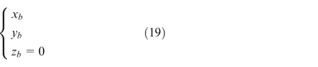
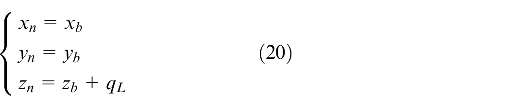
According to the system configuration as Figure 6, it includes
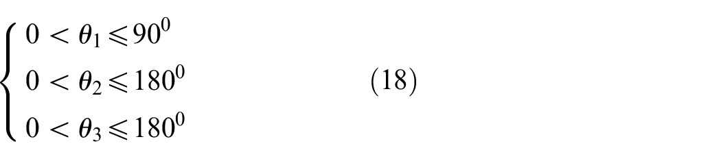
For the base of mobile manipulator, the kinematic constraints should be
The constraints of lifting table are
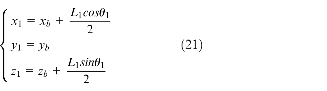
Link 1:
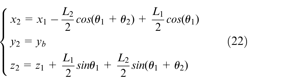
Link 2:
To conduct the system parameter, kinetic energy for each component is analyzed as below
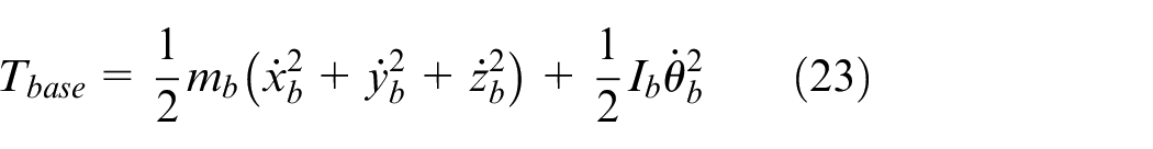
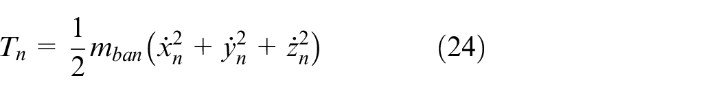
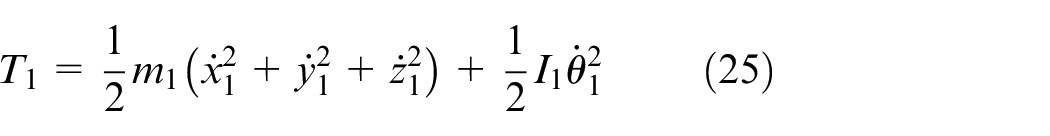
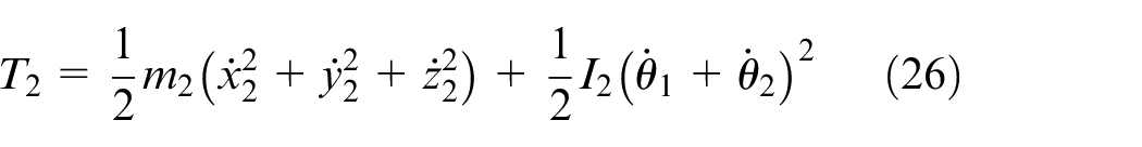
Totally, kinetic energy of this system is

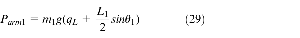
It is assumed that the origin of potential energy is located at the center of robotic platform. By some geometric computations, we have

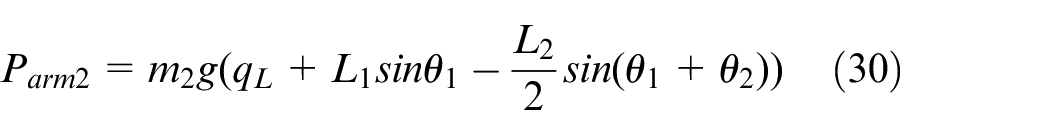
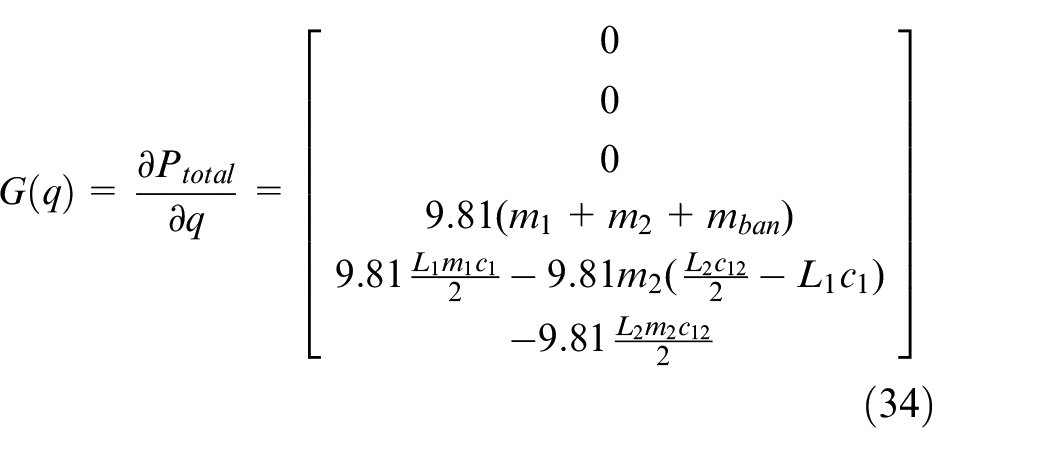
Using the Lagrange method, we obtain

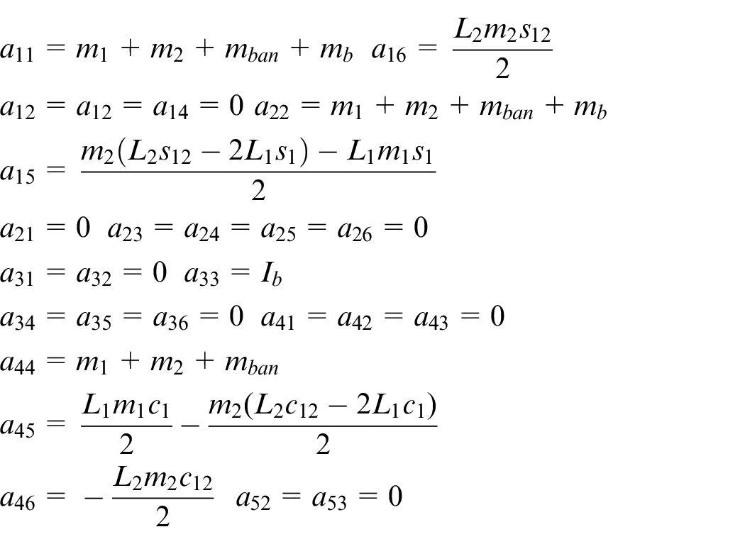
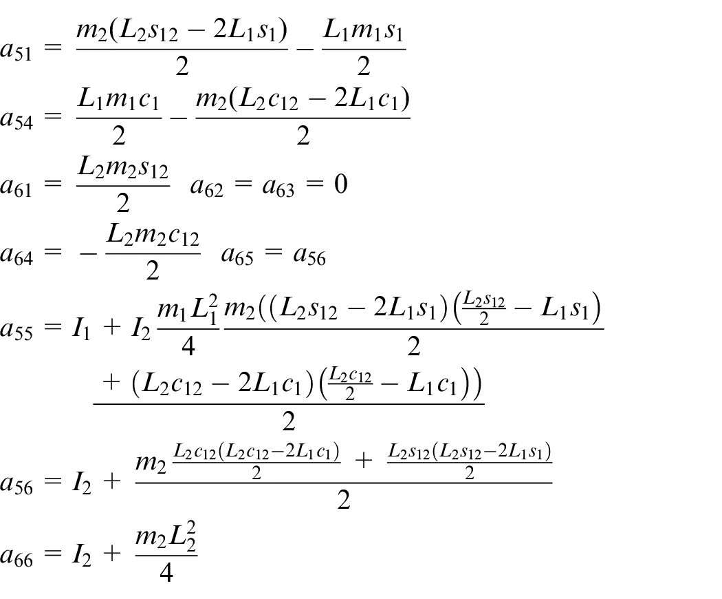
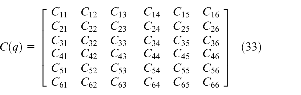
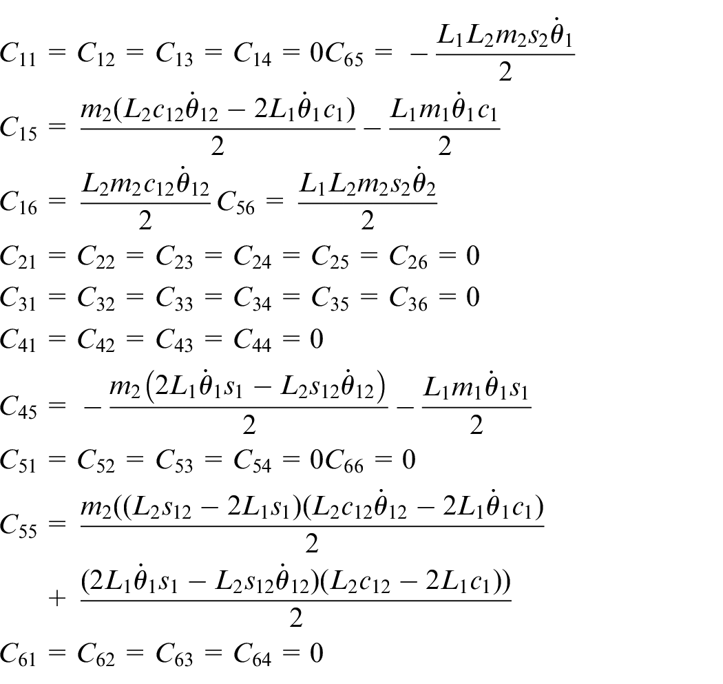
Later, the inertia matrix must be determined as below
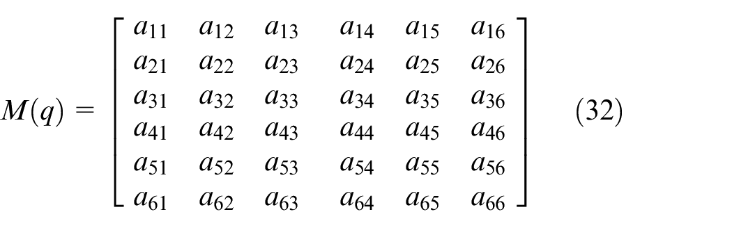
where
Similarly, we have
where
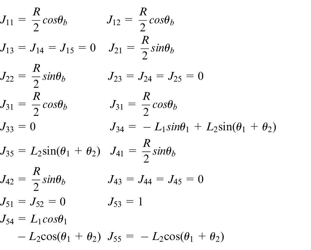
To compute Jacobian matrix

Or

Therefore, location of end-effector could be expressed as
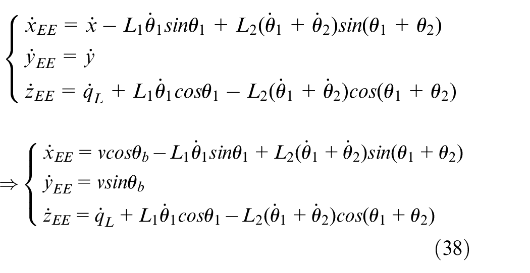
Or,
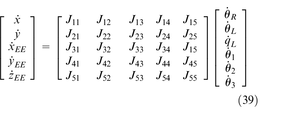
where
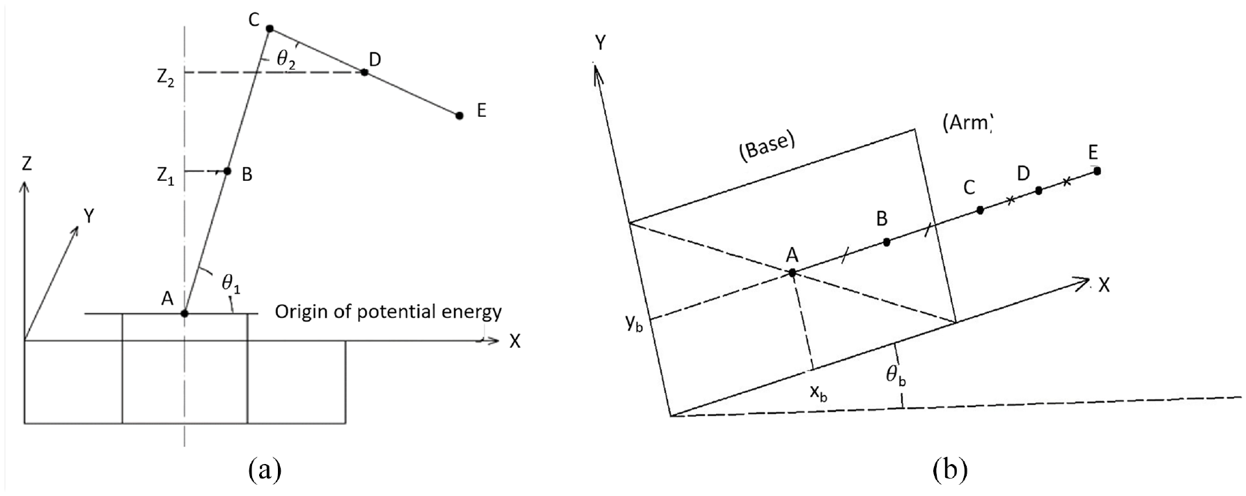
Modeling of the proposed system, (a) side view and (b) top-bottom view.
Modeling of the proposed system with angular displacement and coordinates.
The proposed motion controller
Design of velocity controller
Number equations

The output variables of mobile manipulator are

With the reference trajectory


Then,
Jacobian matrix
From (4) and (5), we have

In the case that the virtual control signal

The Lyapunov candidate function could be chosen as
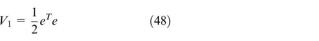
Deriving above equation, we also have
The control law
where

Hence,

When
Design of torque controller
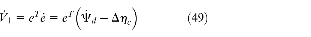
We choose Lyapunov candidate function as below
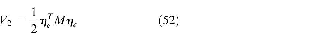
where

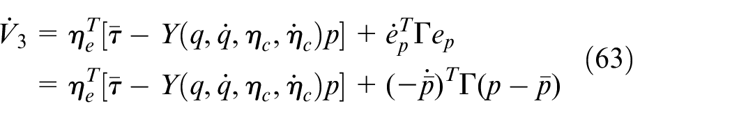
Deriving equation (42), it becomes
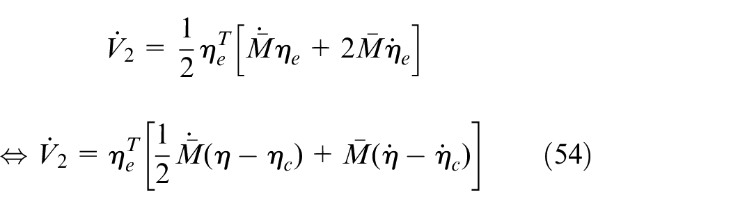
From the dynamic equation, we have
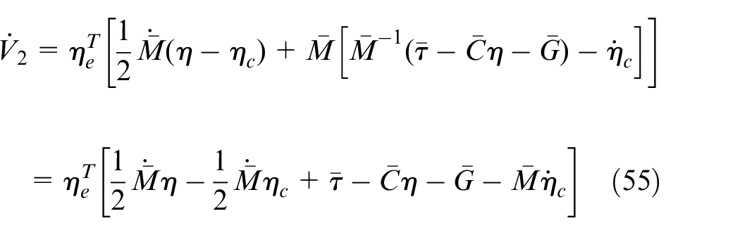
Then,
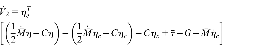

Using equation in previous section, we obtain

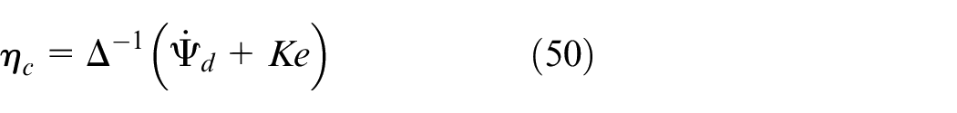
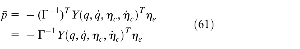
Later, the control law

where
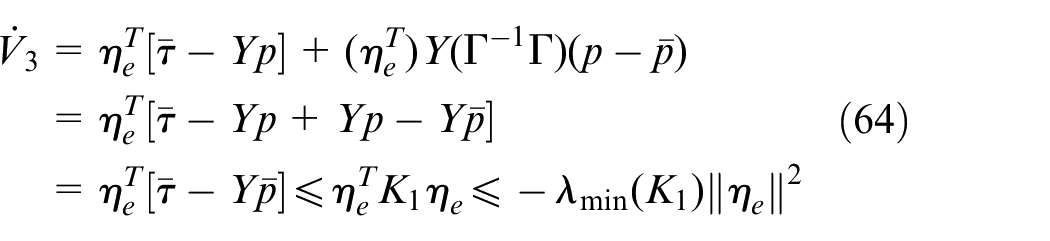
This controller is stable since equation (57) is re-written as

However,

Therefore,
where
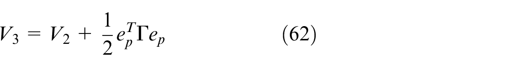
Its derivative could be achieved as
Substituting above controller,
Using Barbalat lemma
23
,

Thus,
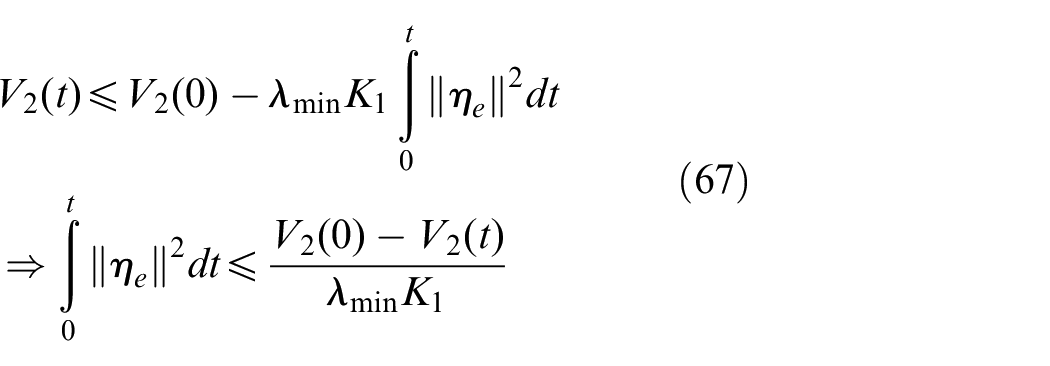
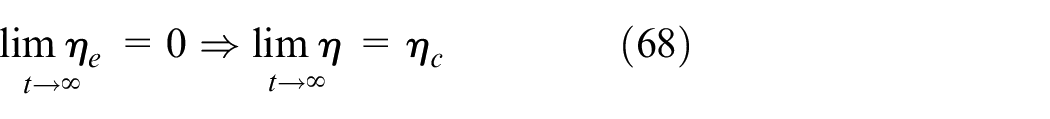
It means that the tracking error of this system would be zero when
Results of study
To verify the effectiveness and feasibility of the proposed approach, both numerical simulation and real-world experiment must be conducted. Hence, practical test scenario comprises hardware platform of WM, dual-finger of gripper, sensing devices and host computer. To complete the handling task, WM should move to target object, pick it up, then travel to destination and place this object as its desire. The structure of our controller is illustrated as Figure 8. There are four main blocks such as velocity controller, adaptive controller, plant model of mobile manipulator and inverse kinematic. In the simulation test, these controllers are presentative to distinguish by functional blocks and wiring connections. On the other hand, they are embedded in different software programming.
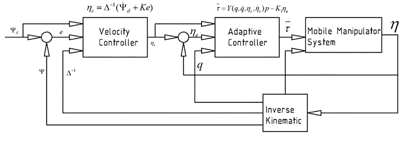
Block diagram of the proposed controller.
Simulation
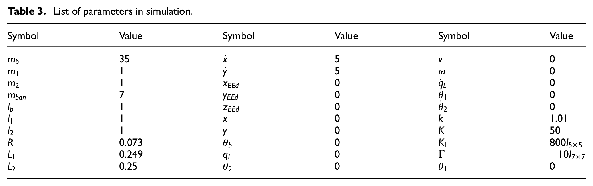
This numerical simulation is validated in Simulink/Matlab software. The technical specifications of host computer are with Intel(R) Core(TM) i7-6600U CPU (Central Processing Unit) 2,60 GHz, 8 GB RAM (Random Access Memory), Windows OS (Operating System) 10 Pro, x64-based processor. In the setting stage, the initial parameters of this system are defined as Table 3. Those values are elected from the physical dimensions of our WM as well as the desired performance.
List of parameters in simulation.
To imitate the variations of practical scenario, our reference signals are considered as
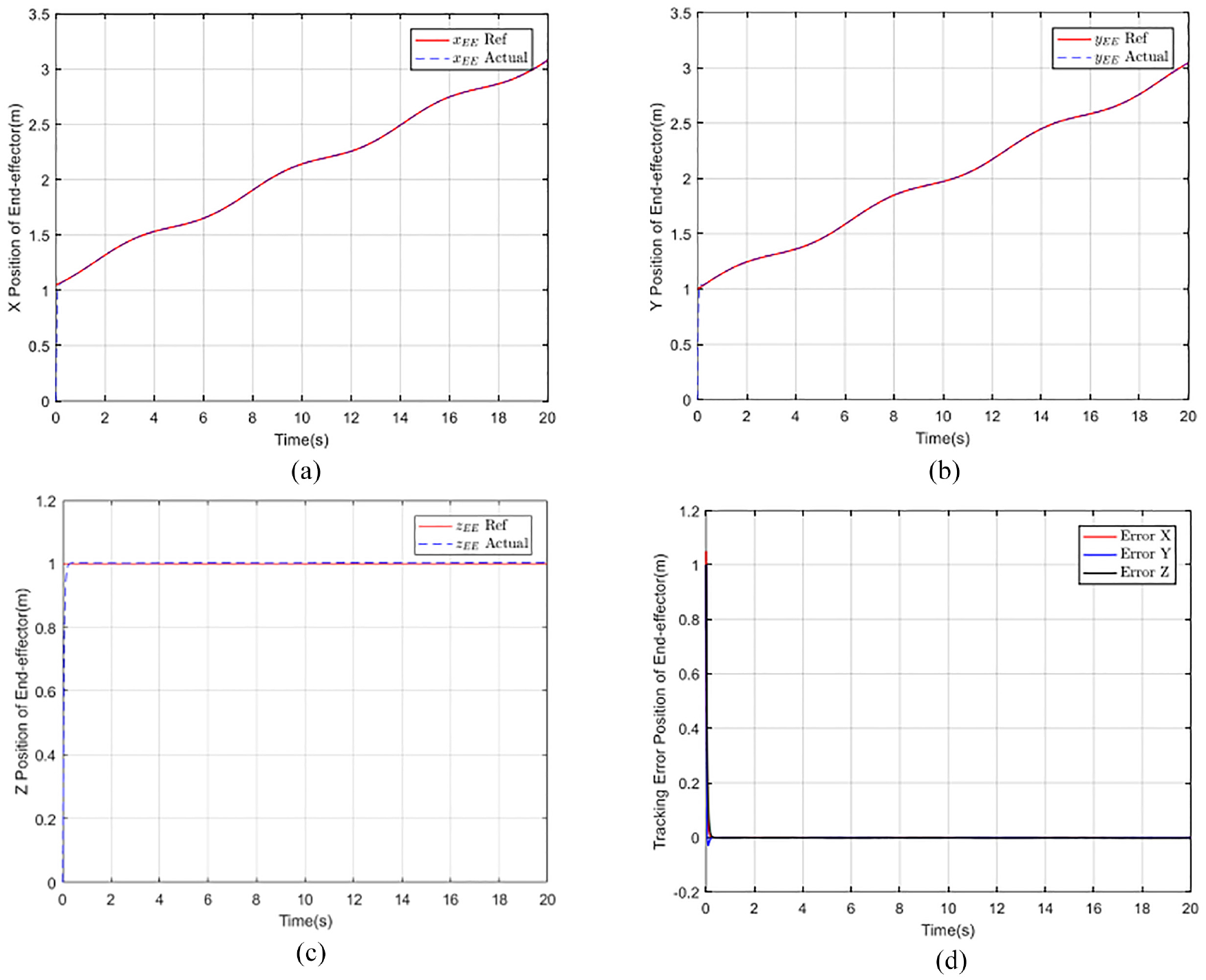
Simulation results of tracking position for the end-effector by using the proposed controller on (a) x axis, (b) y axis, (c) z axis, and (d) the tracking errors.
Additionally, the response of our system is prompt and has instantaneous effect on the output signals. In detail, actual velocity of mobile platform could immediately track its reference as Figure 10(a) and (b) when this system is activated. Observing Figure 10(c), it can be stated obviously that the system parameters are well-tuned to adapt with many variations during its operation. The output torques to drive servo motors could be shown as Figure 10(d). Since the system stability is warranted, driving torque maintains at a constant value. For the reason that it requires to handle robotic gripper at a specified location, its torque at link two might be larger.
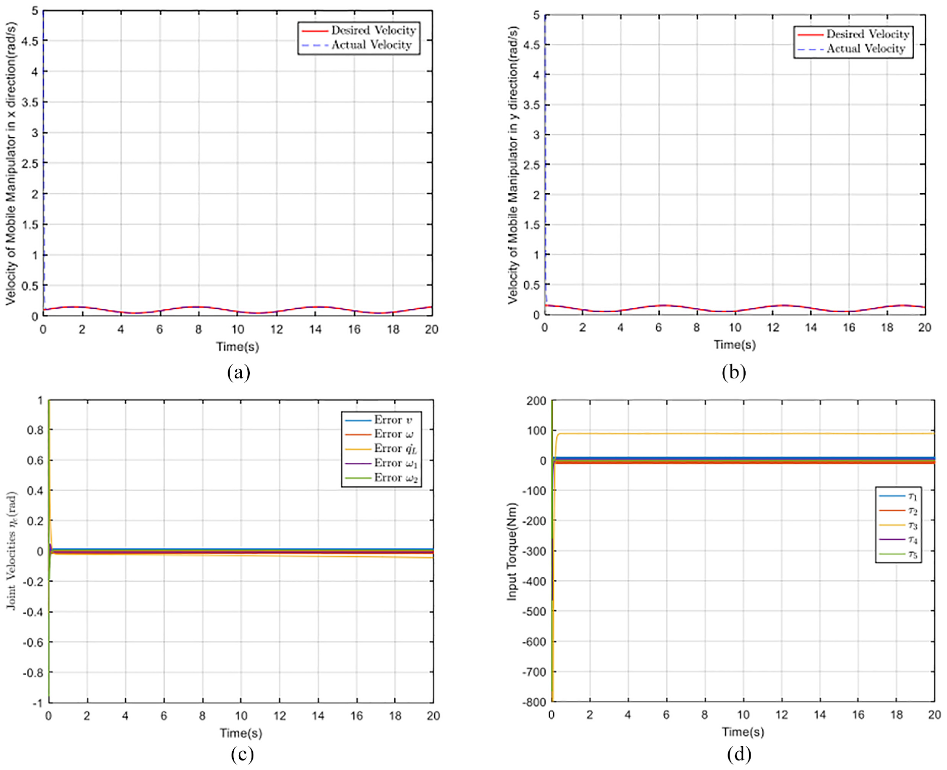
Simulation results of tracking velocity for the mobile platform by using the proposed controller on (a) x axis, (b) y axis, (c) velocity error and (d) output torque for each driving motor.
Experiment
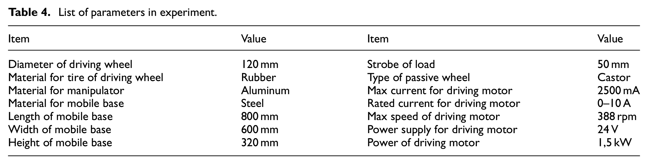
According to the proposed design, hardware platform of our WM as Figure 11 is built to prove the efficiency and practicality of technical specifications as Table 4. In the indoor environment, robot autonomously moves toward to an object, then drive robotic manipulator to pick it. After that, WM turns its direction and travel to destination and place an object.
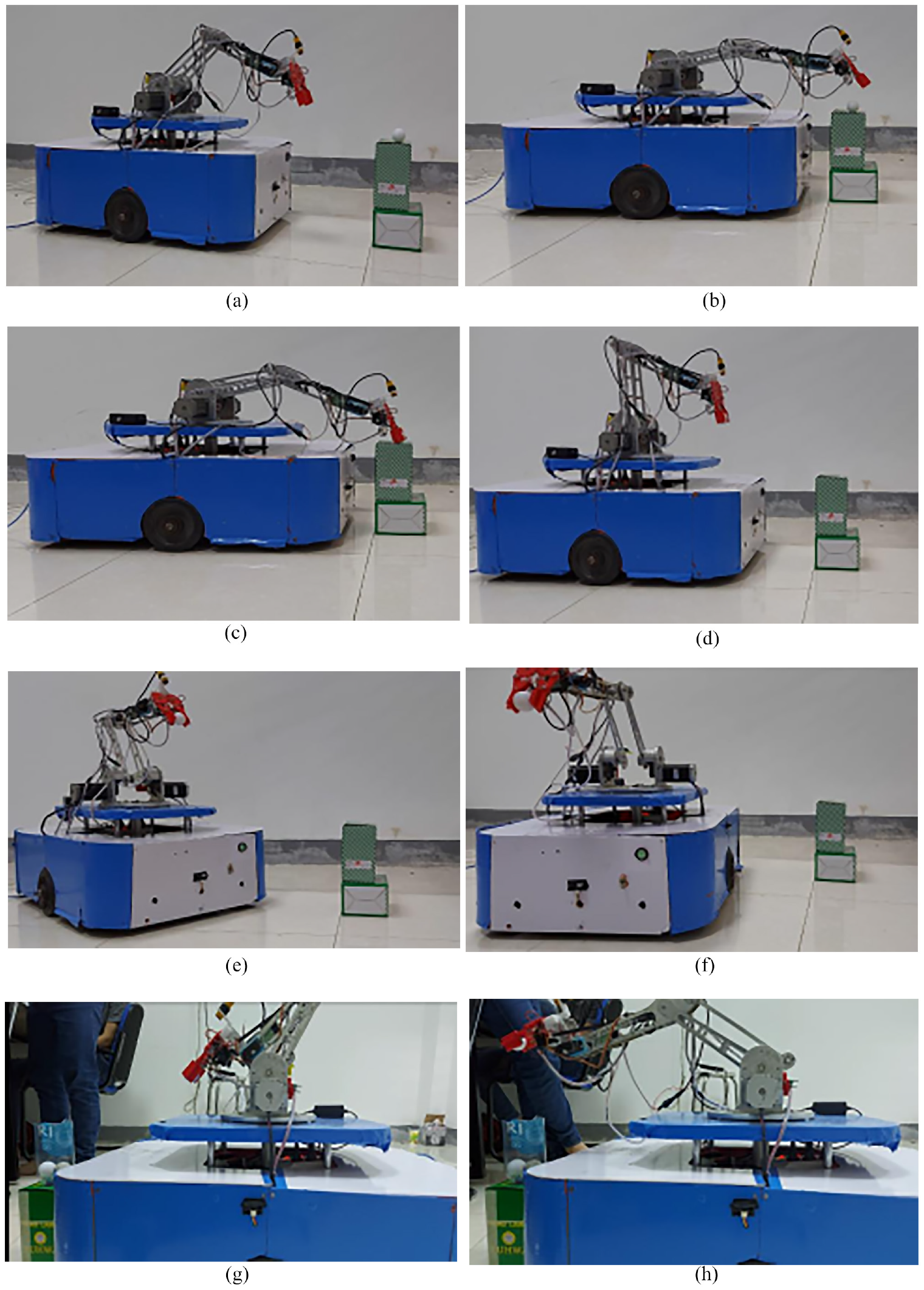
Practical experiments of picking and placing an object by using the proposed controller.
List of parameters in experiment.
In the real platform, data acquisition from various sensing sources is measured by our controller. To estimate the traveling angle of each joint, DC servo motor feedbacks its signal to compute the angular rotation. In the mobile base, two positioning sensors in both active wheels are directly attached to the shafts of driving motors. They are utilized to measure the location of this robot in the surrounding environment. For loading an object, it is necessary to assign the force sensing unit in the inside surface of gripper. This sensor is very thin, sensitive and measurable by forwarding the electric signal to main controller. With these mechanisms to collect data, WM has enough information to work well in the setting situation.
Besides, the tracking performance of end-effector is depicted as Figure 12. Owing to the pre-determined trajectory, WM handles its manipulator to follow although it may suffer some uncertainties or errors in the real environment. In Figure 12(d), torque sensors are attached in two fingers of gripper so that robot could sustain the grasping force. Moreover, the tracking velocity of mobile platform is recorded in Figure 13. From these results, the motion control of WM still preserves stably and sustainably.
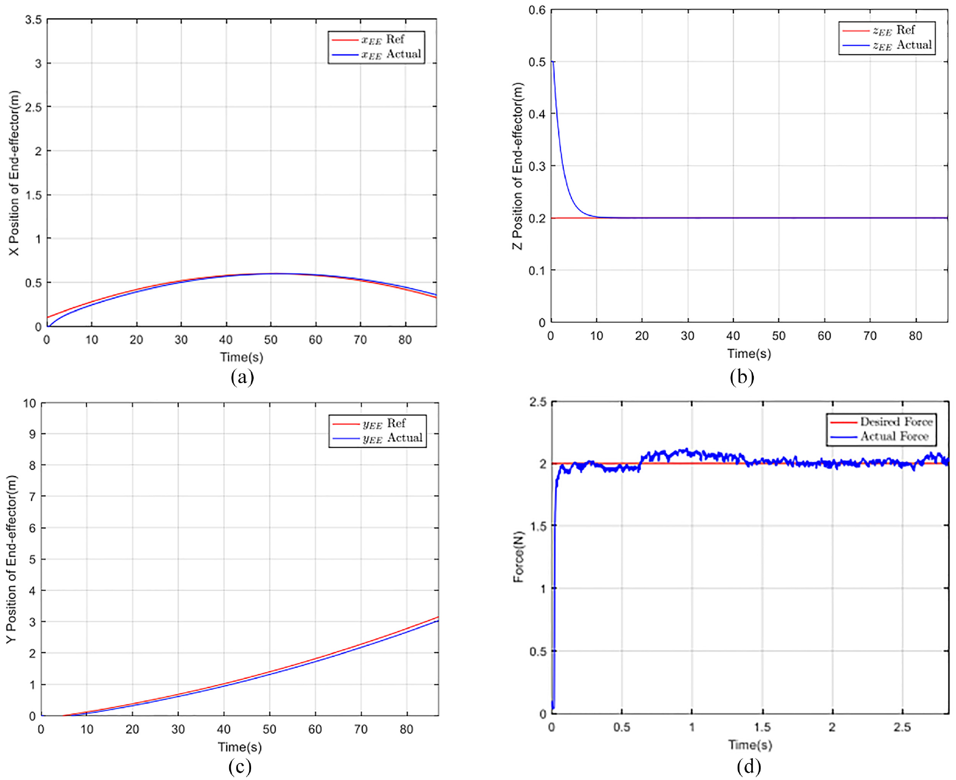
Practical results of tracking position for the end-effector by using the proposed controller on (a) x axis, (b) y axis, (c) z axis, and (d) interactive force when grasping an object.
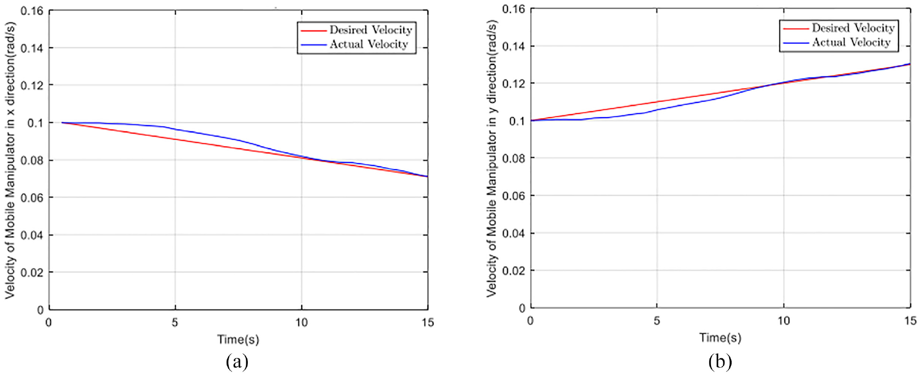
Practical results of tracking velocity for mobile platform by using the proposed controller on (a) x axis and (b) y axis.
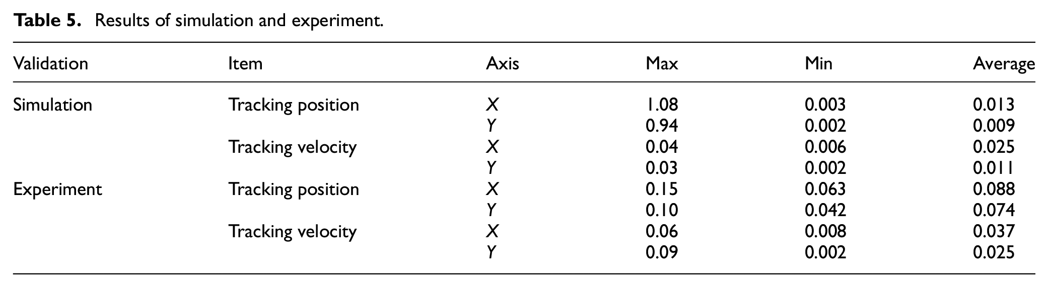
To summarize our validations in both numerical simulation and experiment, Table 5 represents the max, min and average values of tracking performance such as positioning error and velocity error. While robot is handling the pick-and-place task, the lifting table which is directly connected to the base of manipulator, is not activated. Since WM locates in front of an object, it spends a lot of efforts to reach target. As a result, the fluctuations of tracking performance on x axis might be larger than y axis. For simulation tests, the average values of tracking positions on x and y axis are 0.013 and 0.009 separately. In detail, the changes in position are also greater on x axis because it needs to track the reference velocity simultaneously. In the experimental verifications, the tracking velocity on x axis is 0.037 in average while the other one on y axis is 0.025. Although max value of tracking velocity on y axis is higher, its min value is still lower owing to the effect of our controller.
Results of simulation and experiment.
Conclusion
In this paper, the systematic design of motion controller for WM was presented. Mobile platform included the DDR structure of driving mechanism while upper manipulator was attached. Dual-finger gripper with force sensors was implemented to grasp an object in target location. Due to the dynamical analysis, both velocity controller and torque controller were designed. By using Lyapunov theory, the proposed system is asymptotically stable. Based on our design, numerical simulation and real-world experiment are accomplished to validate the properness and feasibility of this approach. The practical results indicate that the maximum values of tracking errors in x and y axis are 12.5% and 8.1% in respect to the desired ones correspondingly. In the tracking velocity, these errors are 16.3% and 13.7% in x axis and y axis respectively. Comparing to the others, this design is beneficial to carry heavier object because of parallelogram mechanism as well as provides more flexible motion and stable movement due to the proposed controller.
For further developments, the advanced control strategies such as machine learning or deep learning could be embedded in order to enhance the high performance of our system. Furthermore, WM integrated the digital camera system can be possibly navigated in the unknown environment. In addition, two or three WMs could collaborate in a group which perform a specific task. Some algorithms for instance swarm optimization or decentralized control can be proper to implement.
Footnotes
Acknowledgements
We acknowledge Ho Chi Minh City University of Technology (HCMUT), VNU-HCM for supporting this study.
Declaration of conflicting interests
The author(s) declared no potential conflicts of interest with respect to the research, authorship, and/or publication of this article.
Funding
The author(s) received no financial support for the research, authorship, and/or publication of this article.
Data availability statement
Data sharing not applicable to this article as no datasets were generated or analyzed during the current study.