
Abstract
The limited battery energy restricts the underwater operation duration of the underwater moored platforms. In this article, a horizontal axis ocean current turbine is conceptually designed to produce power for the underwater moored platforms and extend their operational durations. As part of the development of the horizontal axis ocean current turbine, a three-dimensional dynamic model of the system is proposed. The underwater moored platform is modeled as a rigid body with the Newton–Euler method and the cable is modeled with a lumped mass method. Motion simulations are then performed to evaluate the motion performance of the moored system under different operation conditions. The influences of the net buoyancy and the ocean current velocity on the motion of the underwater moored platform are investigated. The simulation results show that the underwater moored platform oscillates in water due to the periodically changed rotor forces. The system has a higher motion stability at a higher net buoyancy, with a smaller horizontal offset and a smaller cable inclination angle. The motion stability of the system also increases with the decreased ocean current velocity.
Introduction
Nowadays, intelligent robots are playing a more and more important role in a plethora of applications. 1 Among the various kinds of robots, increasing emphasis has been put on the development and improvement of underwater moored platforms (UMPs). UMPs are a class of underwater robots which are tethered to the seabed using mooring cables. UMPs have broad applications in both civil and military missions, such as underwater monitoring (oceanographic sensors), 2 communication (acoustic communication nodes), 3 defense (moored mines), 4 and multi-object missions (self-moored autonomous underwater vehicles (AUV)), 5 with expected performance durations typically ranging from months to years. The biggest concern for the UMPs is the duration of their underwater operation, which is mainly determined by the total energy contained in the onboard batteries and the consumption of energy by the electronic devices. Although most UMPs are designed by low-power techniques, the operation durations are still non-satisfying due to the limited battery energy. Extending the operational life of UMPs can significantly reduce the cost for missions where a sustained presence is required. UMPs are often deployed where ocean currents are consistently available. The kinetic energy stored in ocean currents provides an ideal alternative to recharge the UMPs. Previous studies have studied the feasibility of using solar energy to power a sensor network. 6 Similarly, the Institute of Unmanned Underwater Vehicles (IUUV) at Northwestern Polytechnical University (NPU) has designed two ocean current turbines, including a vertical axis ocean current turbine (VAOCT) 7 and a horizontal axis ocean current turbine (HAOCT), 8 to extract energy from the ocean currents and power the UMPs. The turbines will be installed on the UMPs as independent units. A previous study proved that the HAOCT had a relatively high coefficient of power of 0.327 and was compatible with a moored AUV. 8 However, most UMPs are moored with an attitude of nose-up and tail-down for a stronger stability against the ocean currents. Therefore, a new type of HAOCT is required for the vertically moored UMPs.
The motion of the UMP system is the result of the coupled forces between the UMP body, the cable, and the HAOCT. Only a few studies investigated the dynamic modeling of the underwater moored ocean current turbines. Vanzwieten et al. 9 proposed a three-dimensional dynamic model for a 1/30th scale model of a moored ocean current turbine, and later, they updated this model by replacing the turbine model with an unsteady blade element momentum method. 10 Comprehensive efforts have been given on the dynamic modeling of underwater towed systems which consist of a surface vessel, a cable (sometimes two or three cables), and an underwater device such as an underwater vehicle.11–15 In these studies, the underwater device and the cable are separately modeled and then coupled together. The underwater device is usually modeled as a rigid body and the dynamic equations are derived from the Newton’s law and Euler’s equation.11–13 While for the modeling of the cable, three common methods can be found in previous studies, including the lumped mass approximation method,16,17 absolute nodal coordinate formulation method,18–20 and finite element method.14,21,22 Each of the three methods has its own advantages and disadvantages and is widely used.
Motion stability of the UMP system is the precondition for the proper operation of the HAOCT and the onboard sensors; therefore, it needs to be investigated before the manufacture of the device. In this study, emphasis is placed on the dynamic modeling of the UMP system. The dynamic model of the UMP body is built based on the Newton–Euler method, and the cable is modeled using the lumped mass method. The coupling effects between the UMP body and the turbine is neglected and the turbine is considered as periodic forces. Motion simulations are then performed to investigate the effects of two key factors, the net buoyancy and the velocity of the current, on the motion characteristics of the system.
The UMP system and the turbine
The UMP considered in this study is an existing model that has a maximum diameter of 0.5 m and a length of 7 m. The HAOCT designed for the UMP must not affect the deployment of the UMP; therefore, a HAOCT with retractable blades is designed, as shown in Figure 1. The blades are installed at the end of a telescopic rotating shaft, which can be controlled to shrink or stretch by a hydraulic system. The hydraulic system is composed of a pump, a valve, and a hydraulic multistage rod. The hydraulic rod, which is controlled by drawing or expelling the seawater using the pump, is connected to the telescopic shaft with a ceramic bearing, helping to control the length of the telescopic shaft and not affect its rotation. The torque generated on the blades is transmitted through the telescopic rotating shaft to a magnetic coupling, then to a gear box, and eventually to a permanent magnet (PM) generator to convert kinetic energy into electricity. The magnetic coupling is used instead of common shaft connections because the magnetic couplings can transmit forces in the magnetic field and the sealing problem can be easily solved by simply adding a shield in the middle of the magnetic coupling. Consequently, the loss of power caused by the friction in common seals can be eliminated.

Composition of the HAOCT: closed (top) and opened (bottom).
Figure 2 shows the HAOCT when the UMP is tethered to the seabed. In the beginning of the deployment, the two blades fit closely to the surface of the UMP without influencing other functions of the UMP. And when the platform successfully moors to the sea floor, the pump inside the HAOCT starts to draw water and make the telescopic rotating shaft to stretch, pushing the blades to the outside of the UMP and generating power for the UMP. Once missions completed, the pump expels water and pulls back the blades, and then, the UMP releases the cable and rises to the sea surface to be retrieved.

Sketch of the UMP in moored state.
Mathematical model
Frames of reference
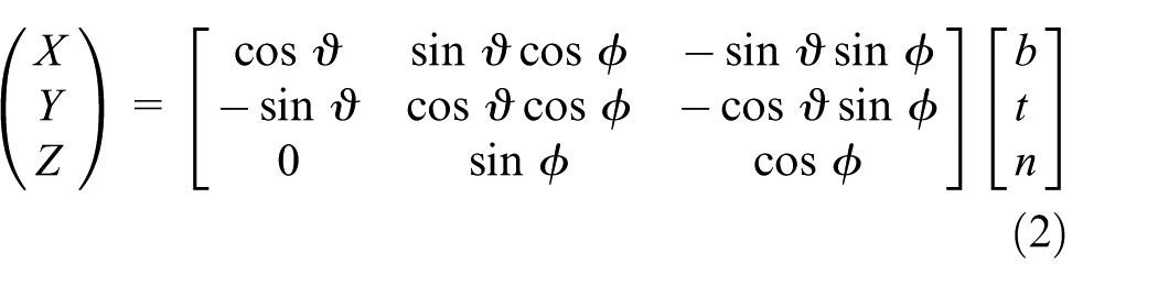
The inertial and the UMP-fixed frames of reference
A UMP-fixed coordinate frame

UMP-fixed frames of reference.
The generalized position vector
The kinematic equations describe the geometrical relationship between the inertial coordinate frame and the UMP-fixed coordinate frame and can be described as follows

where

and

Cable-fixed frames of reference
The cable-fixed frames of reference are used to calculate the forces and positions of the cable elements. These frames,

Cable-fixed frames of reference.
The geometrical relationship between the cable-fixed frame and the inertial frame can be described as follows
where
Dynamic model for the UMP
The vehicle has 6 degrees of freedom. Based on Newton’s law and Euler’s equation, the translational and rotational dynamic equations of the vehicle are expressed in a compact form 23

where

where
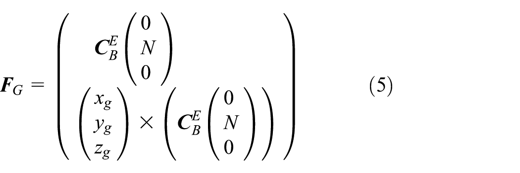
Gravity and buoyancy
The gravity and the buoyancy both act along the inertial EY axis and are treated together
where
Added-mass force
The added mass represents the effect of fluid being accelerated by the UMP when it accelerates in water. The added-mass forces can be calculated by

where

where
Hydrodynamic forces
The hydrodynamic forces,

where
Rotor forces
The interactions between the UMP and the rotor are complicated, and it is hard to model the rotor forces directly. A common method is to simplify the rotor as two forces, including a thrust,

Thrust and torque of the rotor varying with time.
The force vector of the rotor is found by

and the torque vector of the rotor is the sum of the initial rotor torques and the torques induced by the rotor forces

where

Cable forces
The cable is modeled as linear elastic finite elements, and a lumped mass approximation method is used to model the forces on each node. Neglecting the bend and twist of the cable, the dynamic equations of the ith node is obtained by applying Newton’s Law 16

where
The forces of cable on the UMP is found by

where
UMP-cable coupling conditions
The top of the cable (node 1) is connected to the UMP; therefore, its position and velocity are the same with those of the UMP. Besides, the dynamic effects of node 1 on the UMP must be considered and equation (3) is updated as

where
Simulation results and discussion
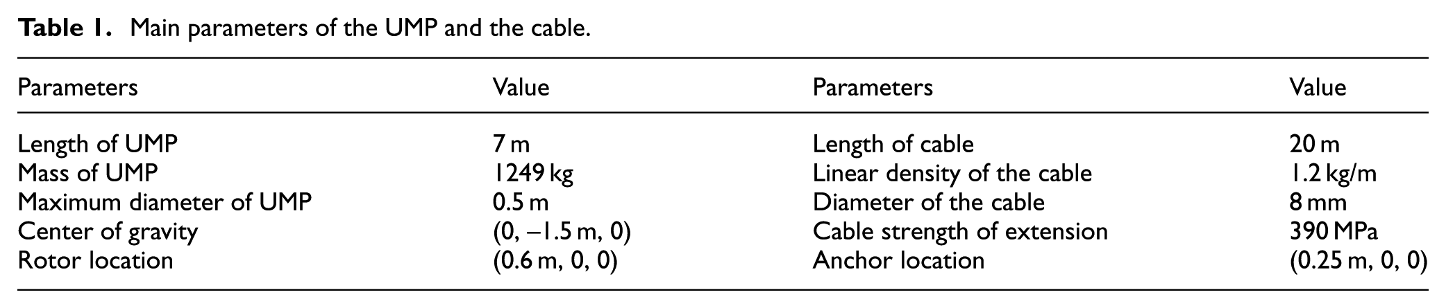
The motion characteristics of the UMP system are determined by the external sea conditions (ocean current velocity) and the design parameters of the platform, such as net buoyancy, center of gravity, length of cable, and the rotor location. Simulations are carried out to evaluate the influences of the above five factors. But due to the limited space, only the results of the two most significant factors, the ocean current velocity and the net buoyancy, are presented in the following contents. Some main parameters of the UMP and the cable are shown in Table 1.
Main parameters of the UMP and the cable.
Influences of net buoyancy on the motion characteristics of the moored system
Simulations for three different net buoyancies, N = 1000, 1200, and 1400 N, are performed. The initial position of the UMP is (0, −13.5 m, 0) and the ocean current velocity is 0.514 m/s pointing to the
Figure 6 shows the generalized position trajectories, including three translational components and three rotational components, of the UMP with different net buoyancies. The position of the UMP converges with oscillation due to the periodic thrust and torque of the rotor. It can be seen in the subfigure of the X-position that the UMP with a larger net buoyancy shows a smaller oscillation amplitude and a faster convergence. In the case of N = 1400 N, the motion converges at about t = 500 s, while in the case of N = 1000 and 1200 N, there is still weak oscillation at the end of the simulations. This means that the larger the net buoyancy, the higher the stability of the platform. In addition, the platform with a larger net buoyancy has a smaller X-position at the end of the simulation, The final X-positions of the platforms with net buoyancy of 1000, 1200, and 1400 N are −4.68, −4.12, and −3.79 m, respectively. The Y-position trajectory of the UMP is similar to that of the X-motion and also converges with oscillation. The larger the net buoyancy is, the smaller the amplitude of oscillation and the faster the convergence. The amplitudes of oscillation in the Y-direction are on the order of 0.1 m that is much smaller compared to that in the X-direction. The movement of the UMP is very weak in the Z-direction, with a maximum value of about 0.003 m, which is far less than those in the X- and Y-directions. Therefore, it can be said that the hydrodynamic forces of the rotor has a greater influence of the X-direction motion and a smaller effect on the Y-direction motion and that the Z-direction motion can be ignored.

Trajectories of the UMP for different net buoyancies.
Figure 6 also shows the variation of the three Euler angles, roll, yaw, and pitch, with time between t = 500–600 s and under different net buoyancy conditions. The three angles change periodically with time. In the subfigure of the roll angle, a larger net buoyancy corresponds to a larger amplitude of oscillation in the roll angle, with values of 2.0°, 1.6°, and 1.5° for N = 1000, 1200, and 1400 N, respectively. Besides, the mean roll angle also increases with the net buoyancy. The torque of gravity relative to the CB is balanced with the torque of the rotor so that the UMP achieves roll stability. Because the volume of the platform is fixed and the net buoyancy is adjusted by changing the mass of the platform, a larger net buoyancy means a smaller gravity and the platform needs a larger roll angle to obtain a larger gravity torque to balance the torque of the rotor. The net buoyancy has little effect on the yaw angle, which changes irregularly around zero and has a mean value of zero. The variation of the pitch angle is much weaker compared to the roll angle, with a maximum peak-to-peak value of 0.015°. The pitch angle changes periodically and has a mean value of zero. The amplitude of the pitch angle increases with the net buoyancy.
Figure 7 shows the shapes of the cable in the EXY plane at the end of simulation for different net buoyancies. It can be seen from the figure that the thrust of the rotor causes the platform to shift in the ocean current direction. The increase in the net buoyancy causes the increase in the X-directional offset and the decrease in the inclination angle of the cable.

Shapes of cable in the EXY plane for different net buoyancies.
Influences of ocean current velocity on the motion characteristics of the moored system
In order to study the influence of ocean current velocity on the motion characteristics of the UMP, simulations for three different ocean current velocities, v = 0.257, 0.386, and 0.514 m/s, are performed and the results are compared. The initial position of the UMP is (0, −13.5 m, 0) and the net buoyancy is 1000 N. The total time of each simulation is 600 s and a time step of 0.05 s is chosen.
Figure 8 shows the generalized position trajectories of the UMP at different ocean current velocities. The ocean current velocity has a great influence on the movement of X- and Y-directions, but hardly affects the Z-motion, which varies on the order of millimeters when the upstream velocity changes. It can be seen in the subfigure of the X-position that the increase in upstream velocity results with a greater amplitude of oscillation and a slower convergence of the movement. Besides, the X-position of the platform decreases with the increase in the upstream velocity. The final X-positions of the platform under upstream velocities of v = 0.257, 0.386, and 0.514 m/s are −2.14, −3.22, and −4.68 m, respectively. This is because that the thrust of the rotor is proportional to the square of the current velocity, and the greater the current velocity is, the greater the thrust will be. The Y-position trajectory of the UMP is similar to that of the X-motion and also converges with oscillation and also decreases with the increased upstream velocity.

Trajectories of the UMP for different upstream velocities.
From the subfigures of the three Euler angles, it can be seen that the amplitude of oscillation increases with the ocean current velocity. Both the yaw and pitch angles fluctuate around zero because of the absence of external forces in the yaw and pitch directions. The mean value of the roll angle increases with the ocean current velocity, with values of 0.11°, 0.26°, and 0.46° for cases of v = 0.257, 0.386, and 0.514 m/s, respectively. This is because that the torque of the rotor increases with velocity and the UMP needs a larger roll angle to obtain the enough torque of gravity to reach the balance of roll motion.
Figure 9 shows the shapes of cable in the EXY plane at the end of simulation for different ocean current velocities. The increase in the ocean current velocity causes the increase in the X-directional offset and the curvature of the cable is decreased.

Shapes of cable in the EXY plane for different upstream velocities.
Conclusion
In this study, a HAOCT was conceptually designed for UMPs to extend their underwater operation time. As part of the development of the HAOCT, a three-dimensional dynamic model of the system was proposed based on the Newton–Euler method and the lumped mass method. Simulations were then performed to study the motion characteristics of the moored UMP equipped with the HAOCT under different operating conditions.
Important results of this research are summarized as follows:
The UMP oscillates in water due to the periodically changed rotor forces.
The Z-motion, yaw motion, and pitch motion of the UMP are much weaker than the other three motion components.
The system has a higher motion stability at a higher net buoyancy, with a smaller X-offset and a smaller cable inclination angle. But the averaged roll angle increases with the net buoyancy.
The system has a higher motion stability at a smaller upstream velocity, and the X-offset and the roll angle decreases with the upstream velocity.
Footnotes
Appendix 1
Handling Editor: Zhaojie Ju
Declaration of conflicting interests
The author(s) declared no potential conflicts of interest with respect to the research, authorship, and/or publication of this article.
Funding
The author(s) disclosed receipt of the following financial support for the research, authorship, and/or publication of this article: This research was supported by the National Science Foundation of China (Grant Nos 51179159, 61572404), the Shaanxi Province Youth Science and Technology New Star Project (Grant No. 2016KJXX-57), and the Fundamental Research Funds for the Central Universities.