
Abstract
Additive manufacturing technology can make products of arbitrary shapes, greatly expanding the design space of lattice structures. Compared with traditional solid lattice structures, the lattice structures with hollow struts have higher flexural strength, which arouses interests of designers recently. However, owing to the more complex shapes of structures, the model generation and design are facing more challenges. In this article, a novel generative design method for the creation of lattice structures with hollow struts is proposed. This method consists of three stages: initialization, analysis, and optimization. First of all, a ground structure is generated automatically based on initial conditions. Then, the finite element analysis is used to get the stress and coordinate information of finite element nodes as well as deformation information of the ground structure. At last, a rapid optimization method is presented based on the idea of mapping the strut equivalent stress to the strut wall thickness to optimize materials distribution. The proposed method is validated through a case study, demonstrating that this method can enhance performance of products while reducing the complexity of the optimization problem.
Introduction
Additive manufacturing (AM) has been defined as a process of joining materials to make an object from three-dimensional (3D) model data, usually layer upon layer, as opposed to subtractive manufacturing methodologies.1,2 The recent improvement of AM technologies have allowed designers to directly manufacture structures of almost arbitrary shapes based on 3D digital model, which expands the design space greatly.3,4 Owing to the characteristics of good energy absorption, strong thermal, and acoustic insulation properties, and most importantly, a high strength to low mass correlation, lattice structures have attracted wide attention of designers among the numerous types of complex structures. 5 A lattice structure with a volumetric density of ρ=0.1 will be roughly three times stronger than a foaming structure. 6 Generally, lattice structures have better mechanical and multi-functional properties in mesoscale. 7 Thus, this article concentrates on mesoscale lattice structures with strut diameters in the range of 0.1–10 mm and strut lengths on the order of centimeters.
The essence of lattice structure design is to optimize the distribution of materials, that is, “put the materials in the place where they are needed.” 8 Traditionally, the optimization of lattice structures is completed by topology methods, mainly including the homogenization method and ground structure method. 9 Bendsøe and Kikuchi 10 proposed the homogenization method first in 1988. This method extends the concept of composite media from the domain of porous materials to topology optimization by means of introducing microstructure in the macroscopic material analysis, which transforms the complex topology optimization problem into a relatively simple size optimization problem. Thus, the performance of the macrostructure can be obtained from different microstructures. The ground structure method is development for discrete structures. It is designed to adjust the initial ground structure, the design variables of which are the shape and size of the cross section. 11 Lattice structures are typical discrete structures, and therefore, designers usually adopt the ground structure method to improve its performance.
However, owing to the large number of struts in the lattice structures, difficulties occurred during the design process. Graf
12
reported that there would be
Additionally, some researchers have made a breakthrough from the structure itself recently. 18 They replaced the original solid struts with hollow struts, which were the shape of tubes. Queheillalt and Wadley 19 designed a kind of light sandwich truss structure formed of hollow struts, the strength of which was much larger than that of the solid truss structure. Pingle et al. 20 adopted the tubular structures of pyramid-shaped arrangement as the sandwich plate and found that the strength was mainly determined by the relative density. When the relative density was greater than 3%, the structure would not bend.
Although lattice structures with hollow struts have better performance, the difficulties of the structures design are also greatly increased due to their complex shapes. In order to improve the design efficiency of lattice structure, a new generative design method is proposed in this article. There are two outstanding characteristics of this method: (1) the lattice structures can be generated automatically under the consideration of directions, which can save much modeling time and (2) the wall thickness of struts are variable to obtain the optimal materials distribution by means of a mapping method, which avoids complex topology optimization.
Basic concepts
Hollow struts
Because hollow struts have higher second area moments than solid struts, the lattice structures constructed with hollow struts are found to be stronger than their solid strut counterparts. 21
The shapes of the cross sections can influence the mechanical properties of the struts. Compared to sections of other shapes, hollow struts with circular sections have higher second moment of area and better flexural behavior. 22 The hollow strut model is shown in Figure 1. The symbol L represents the length of the strut. The symbols R and r represent the outer radius and inner radius, respectively. Then the wall thickness of the strut can be expressed as


Hollow strut model.
Therefore, the key to determine the wall thickness of the strut is to determine its outer radius and inner radius. The full representation of a hollow strut is shown below

where

Comparison of optimized lattice unit cell with solid struts and hollow struts: (a) solid lattice unit cell, (b) hollow lattice unit cell, and (c) hollow lattice unit cell with two struts removed for visual display. The struts in (b) and (c) have identical outer radius and different inner radius.
Lattice structure and lattice frame
It is necessary to introduce the concept of lattice frame beforehand. The lattice frame is a graphical representation model which is composed of the nodes, the line segments, and the topological relations among the nodes. The relationship between the lattice frame and lattice structure is shown in Figure 3. Lattice frame plays an important role in the design of the lattice structure. The lattice frame can be converted to the lattice structure based on a given strut thickness list.
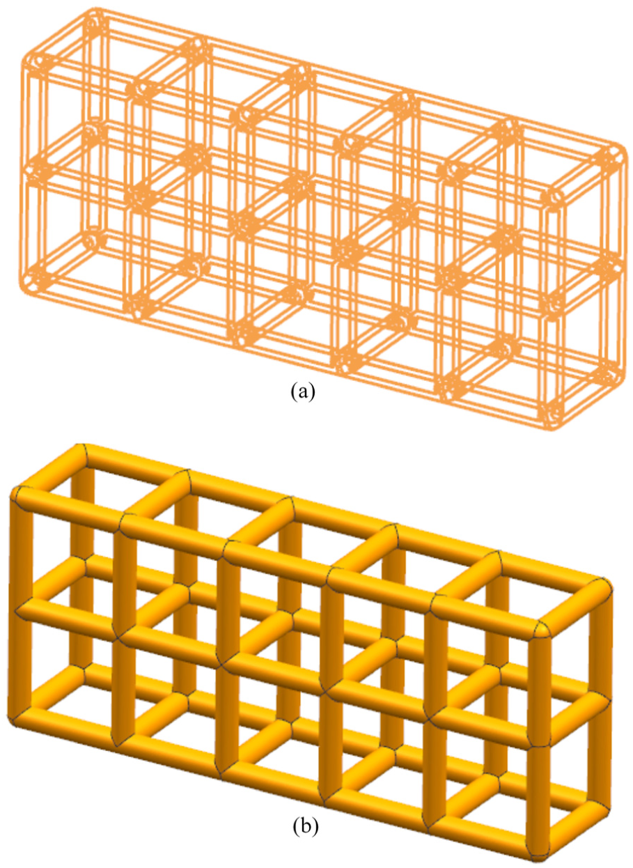
The relationship between: (a) a lattice frame and (b) a lattice structure.
Ground structure
Ground structure is the initial structure of the topology optimization. 23 In topology optimization theories, the optimum topology is a subset of a ground structure. The performance is optimized by adding, deleting, and modifying parts of the ground structure. In this article, the ground structure is the initial structure of identical outer radius and inner radius which need to be further adjusted. The cross sections of the struts become design variables of the optimization problem. The ground structure is generated according to the given conditions. Since hollow structure of arbitrary directions is difficult to generate, this article will make it in the following section.
Design method
The proposed design method aims at optimizing the materials distribution of lattice structures while meeting mechanical performance requirements. As illustrated in Figure 4, it consists of three design stages: initialization, analysis, and optimization (IAO). As previously mentioned, this IAO method gains efficiency by avoiding topology optimization on explicit lattice structures. The first design stage is called the initialization stage, where the ground structure is generated based on the initial conditions. Moreover, the direction of the ground structure can be designed according to the intentions of designers. In the second design stage, the finite element analysis is carried out on generated ground structure. Information including equivalent stress and coordinates of nodes as well as deformation of ground structure is recorded at the same time. Last but not least, a mapping method is used to optimize wall thickness of the lattice struts, further improving performance of the part. These three design stages will be discussed in the following three subsections.

Schematic illustration of the IAO stages during the design process of an AM lattice structure: (a) define the design space and give the constraints, (b) the initial ground structure with hollow struts of identical wall thickness is obtained with the automatic generation method, (c) results of finite element analysis are obtained, and (d) the explicit lattice structure is obtained from the mapping method.
Initialization
The aim of this stage is to generate the ground structure based on initial conditions. This stage can be divided into two main design steps.
First, a lattice frame is generated based on the given conditions including the length of struts, structure direction, and unit cell number in x-, y-, and z-axis directions, respectively. The nodes coordinates of lattice frames along the x-, y-, and z-axis are easily calculated, which are regarded as base lattice frames. Lattice frames in arbitrary directions can be obtained through rotating from base frames. As shown in Figure 5, the angle between the desired lattice frame and base frame is α. Actually, the base frame is generated first during the 3D modeling process. And then, it is rotated to generate the desired lattice frame.
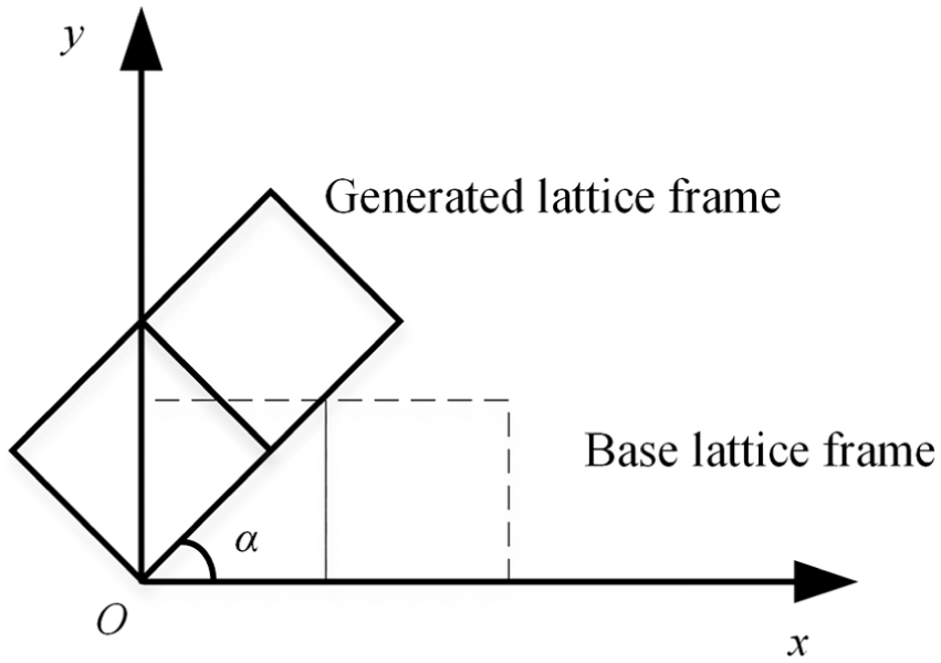
Base lattice frame and desired lattice frame.
The rotation transformation between lattice frames is in fact the coordinate transformation between the corresponding points. The transformation equation between graphs in the n-dimensional Euclidean space is shown by equation (3)

The 3D lattice frame is generated after two rotation steps from the base lattice frame: rotating α degrees around the origin of in the XOY plane first, and then rotating

The nodes coordinates of the lattice frame can be obtained with the help of equation (5)

Second, the ground structure is generated from the lattice frame when given the outer radius and inner radius of struts. The wall thickness of each strut is identical in the ground structure. Assuming the outer radius, the number of struts, the target volume, and the length of struts are R, i, V, and L, respectively; the inner radius of struts can be obtained by

In this way, we can get all the parameters needed for the ground structures modeling. According to the requirements of designers, the ground structures of any direction can be generated automatically based on UG NX9.0 secondary development technology. A strut model can be obtained through Boolean operation with two cylinders of different radius. Some lattice structures of different α and

Hollow lattice structures of different directions.
Analysis
In the second design stage of the proposed method, finite element analysis is carried on the ground structure. The analysis results include lots of finite element nodes. It is necessary to distinguish the finite element nodes from the lattice structure nodes. The full representation of the finite element analysis nodes is shown by equation (7)

where the symbol Q represents the finite element nodes set; the symbol n represents the number of finite element nodes; the symbols x, y, and z represent the coordinates of the finite element node i; the symbol
In addition, the deformation of the ground structure under the action of outer load should also be recorded, which is used to measure the stiffness of the structure.
Wall thickness optimization
The struts of the ground structure have the same wall thickness, which needs to be optimized to get better performance. “Optimal performance” means that structures can withstand the maximum external load in the case of a certain volume or that structures have the minimum deformation in the case of a certain volume and external load. The formulation of the proposed optimization problem for lattice structure can be approached as a size optimization problem as well as a multiple objective design problem. Typically, this problem is formulated with the compromise decision support problem (cDSP). 24 The mathematical representation for the optimization problem is expressed in Table 1.
Mathematical cDSP formulation for the optimization problem.

cDSP: compromise decision support problem.
In Table 1, the symbols GS, Vt, and
In the case of a certain volume of materials, the materials required for each strut are determined by the size of the strut’s equivalent stress value. More materials should be distributed on struts with greater stress, which can improve the utilization ratio of materials. Therefore, this article presents the idea of mapping the strut equivalent stress to the strut wall thickness.
The stress distribution space can be represented by Ps, and the wall thickness geometry can be represented by Pt. Then, the mapping idea can be expressed in the following form

where the symbol

Hollow lattice structures of different rotations.
The struts have the same outer radius instead of inner radius. The strut of greater stress has the smaller inner radius. In order to obtain exact wall thickness values, there are two problems remaining to be solved: (1) average stress of each strut and (2) the mapping function.
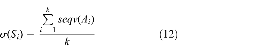
The stress value of a strut is obtained by calculating the average stress value of the finite element nodes located on the strut. So it is necessary to judge the position relation between the finite element nodes and struts, which can be expressed in the following form

where the symbol Q represents the finite element nodes set; the symbol S represents the struts set. The symbol n represents the number of finite element nodes; the symbol m represents the number of struts. The symbol ∈ represents the meaning of “located on.” The problem is to find out a subset of Q that located on the corresponding strut according to the above information.
A strut model can be obtained through Boolean operation with two cylinders of different radius. This problem is equivalent to judging the position relationship between the finite element nodes and the outer cylinders of each strut, which is easier to work out. So this problem can be further transformed into a mathematical model
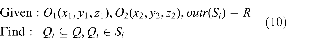
The centers of two end surfaces of the strut Si are O1 and O2. The symbol outr represents the outer radius of the strut Si. The goal of the mapping method is to find out a subset of the finite element nodes set which is located on the strut Si at the same time.
As is shown in Figure 8, there are three kinds of position relations between finite element nodes and struts. The finite element node A belongs to the strut Si only when A and Si are in the relation shown in Figure 8(c), the mathematical expression is

where the symbol L represents the axis of the strut; the symbol

Position relation between finite element nodes and struts: (a)
The position relationship between finite element nodes and struts is determined using an automatic judgment algorithm developed by authors shown in Figure 9.

The algorithm to determine the position relationship between finite element nodes and struts.
The finite element nodes on the strut Si can be expressed as
The outer radius and inner radius of the strut can be obtained based on the mapping formula

The outer radius is determined by the strut with the maximum volume, which is regarded as a solid strut. The outer radius is the same as the radius of the solid strut.
Considering the precision of the 3D printer and computer-aided design (CAD) software, the wall thickness and the inner radius of struts shall not be too small. The range of these parameters in this article is as follows

where the symbol
Case study
In this section, a design optimization case for a 3D cantilever beam, shown in Figure 10, is given to validate the proposed design method of lattice structures with hollow struts. The beam is fixed at one end with a vertical 100-N load applied on the beam tip. The goal of the design is to have as small a deflection as possible while maintaining a volume of 1600

The 3D cantilever beam example.
Initial properties for the 3D cantilever beam.

3D cantilever beam: three-dimensional cantilever beam.
Based on the generating method discussed earlier, a ground structure is determined after the initial design stage, as is shown in Figure 11.
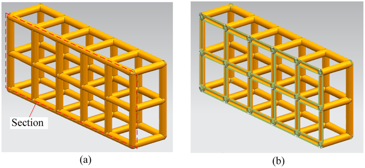
Ground structure model: (a) axonometric drawing and (b) sectional drawing.
The mechanical properties of the ground structure are analyzed using ANSYS Workbench 15.0. The results of finite element nodes distribution and the structure deformation are shown in Figure 12. The geometric and performance parameters are given in Table 3.

Finite element analysis: (a) finite element nodes distribution and (b) structure deformation analysis.
Values of parameters of the ground structure.

Based on the generated ground structure and finite element analysis results, the outer radius and inner radius can be obtained through the mapping method. The position relationship between finite element nodes and struts is determined using the algorithm in Figure 9. The maximum strut volume is 73.18 mm, and this strut is regarded as a solid strut. Theoretically, the outer radius is 1.525 mm. Considering the minimum wall thickness
The inner radius distribution after optimization is shown in Figure 13. Actually, most of the struts bear a small stress. Thus, the wall thickness of most struts is less than 0.2 mm. The struts of high stress have greater wall thickness, four of which are even more than 1.1 mm. This proves that the IAO method can effectively regulate the wall thickness of the hollow struts and achieve the goal of “distributing materials according to needs.”
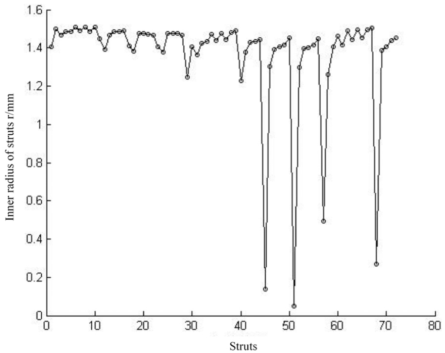
The inner radius distribution of struts.
Based on the outer radius, the inner radius list, and the generating method in the first stage, the optimal lattice structure is generated. As is shown in Figure 14, more materials are distributed on the struts close to the fixed end of the structure. On the contrary, the wall thickness of the struts close to the beam tip is rather small. The results can tally well with the finite element analysis model and the actual stress distribution of the 3D beam cantilever.

Optimized lattice structure.
The performance comparison of the solid lattice structure, the ground structure with hollow struts of the same wall thickness, and the optimal lattice structure with hollow struts of variable wall thickness is shown in Figure 15. The strength of lattice structures is determined by the relative density

where

Comparison of relative density and deformation.
In order to explore the effect of directions on performance, lattice structures with multiple directions are automatically generated using the proposed method. The angle between the structures and the XOY plane are 0°, 5°, 10°, 15°, 20°, 25°, 30°, 35°, 40°, 45°, 50°, 55°, 60°, 65°, 70°, 75°, 80°, 85°, and 90°, respectively. The angle between the external force and vertical direction is 45°. The deformation of the lattice structures in different directions is shown in Figure 16. It can be seen that the strengths of structures vary widely. When the external force is loaded along the diagonal direction of the cantilever beam, the beam has the minimum deformation.
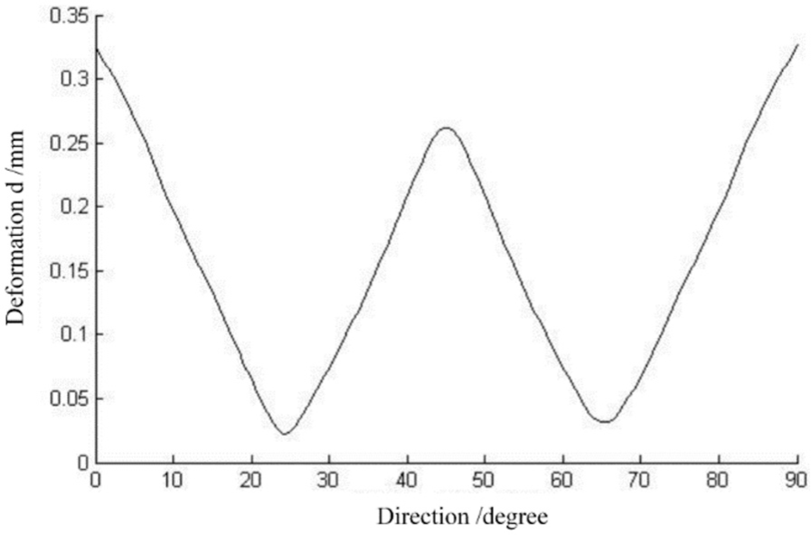
Deformation of structures in different directions.
The number of unit cells can also have an effect on the cantilever performance. We adjust the number of cells in the 45° direction to study the change in deformation. The results are shown in Table 4. The 3D cantilever beam’s deformation is influenced by the number of unit cells. The beam has the minimum deformation when the numbers of unit cells are 6, 1, and 3, respectively. The reason for this phenomenon is that an average stress of each strut is used to make the wall thickness optimization. If a strut is long and the stress gradient is great, parts of the strut bearing much force may be distributed less materials due to the small average stress of the strut and vice versa. So a proper ratio of length to diameter of struts can lead to better optimization results.
The effects of changes of the cell number on deformation.
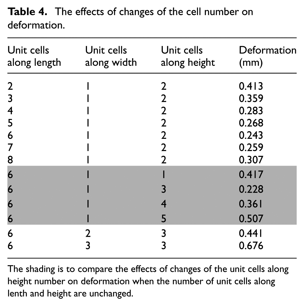
The shading is to compare the effects of changes of the unit cells along height number on deformation when the number of unit cells along lenth and height are unchanged.
Conclusion
In order to improve the performance of lattice structures, an IAO generative design method is presented, which can avoid the use of complicated topology optimization. In the initialization stage, an auto-generating method for the lattice structures with hollow struts is proposed. It not only improves the efficiency of modeling but also meets the direction requirements of the designers. Then, the finite element analysis is used to get the stress and coordinate information of finite element nodes as well as deformation information of the ground structure. In addition, based on the idea of mapping the strut equivalent stress to the strut wall thickness, the optimization of wall thickness of struts is realized. More materials are distributed on struts with greater stress, which can improve the utilization ratio of materials and obtain better mechanical performance. The proposed method is validated through a 3D cantilever beam case. The strength of the beam improves a lot after optimizing using the IAO method.
In this article, the hollow struts are designed in the form of hollow cylinders. Hollow struts with other kinds of cross-sectional shapes need to be explored in the future.
Footnotes
Handling Editor: David R Salgado
Declaration of conflicting interests
The author(s) declared no potential conflicts of interest with respect to the research, authorship, and/or publication of this article.
Funding
The author(s) disclosed receipt of the following financial support for the research, authorship, and/or publication of this article: This research was supported by National Hitech Research and Development program of China (2015BAF04B02).