
Abstract
This review analyses the design, mechanical behaviors, manufacturability, and application of gradient lattice structures manufactured via metallic additive manufacturing technology. By varying the design parameters such as cell size, strut length, and strut diameter of the unit cells in lattice structures, a gradient property is obtained to achieve different levels of functionalities and optimize strength-to-weight ratio characteristics. Gradient lattice structures offer variable densification and porosities; and can combine more than one type of unit cells with different topologies which results in different performances in mechanical behavior layer-by-layer compared to non-gradient lattice structures. Additive manufacturing techniques are capable of manufacturing complex lightweight parts such as uniform and gradient lattice structures and hence offer design freedom for engineers. Despite these advantages, additive manufacturing has its own unique drawbacks in manufacturing lattice structures. The rules and strategies in overcoming the constraints are discussed and recommendations for future work were proposed.
Keywords
Introduction
Gradient forms are common in nature, it can be found in the microstructure of animals, plants, and in human bones. For example, the microstructure of a bamboo is a gradient porous structure with high porosity outside the surface surrounding the circulate structure of the bamboo and lower porosity approaching the inner surface. 1 Other gradient porous structures in living organisms are found in butterfly wings, 2 femur, and trabecular bones.
Over the years, a great number of literature discussed additive manufacturing (AM) technology in building accurate low-density metallic lattice structures. AM technologies are favorable compared to conventional machining because of its ability to manufacture complex parts directly from the computer-aided design (CAD) model to end-user part. In addition, the amount of energy used by AM is far less than conventional machining in terms of tooling and workers. 3
Lattice structure is a porous structure formed by arranging unit cells where its patterns influence the mechanical performance of the structure. Lattice structures offer great opportunities when providing high-strength and lightweight structures compared to non-lattice or solid structures, for example, in the automotive 4 and aerospace industries. 5 However, the significant difference between uniform lattice structures (ULS) and gradient lattice structures (GLS) is the layer-by-layer destruction mechanism when force is applied on it. In addition, GLS can produce specific strength in a specific area in the structures by varying the density of the structure throughout the volume.
This article presents a review on the integration of lightweight GLS in AM on how its mechanical behavior varies when the design parameters are improvised from ULS. The manufacturability of lattice structures and its limitations as well as strategies to reduce the constraints are also discussed. Recommendations for future work regarding lattice structures are discussed in each topic.
Lattice structure
Introduction on lattice structure
Lattice structures are hollow structures with three-dimensional (3D) unit cells arranged periodically with high strength-to-weight ratio characteristics. It can be used to obtain lightweight structures. 6 In 2016, Dr Dhruv Bhate reported that cellular solids can be classified into four categories: honeycomb, open-cell foam, closed-cell foam, and lattice structures, as shown in Figure 1. Each unit cell possesses different mechanics and properties because the properties of lattice structures depend directly on the shape and structure of the unit cell itself. 7 This section discusses recent literatures on the design and mechanical behaviors of lattice structures.

Cellular solids classification: (a) open-cell foam, (b) closed-cell foam, (c) honeycomb, and (d) lattice.
Variations of topologies and their mechanical behaviors
There are various types of lattice structures. The fundamental step in constructing lattice structures is the stacking of unit cells in x, y, and z directions. 8 Depending on its configurations, each one has its own characteristics. 9 A series of cubic lattice structures have been proposed which consist of body-centered cubic (BCC), face-centered cubic (FCC), vertex-centered (VC), edge-centered (EC). Table 1 summarizes and describes the unit cell topologies introduced from previous literature. The Boolean combination of two FCCs and BCC forming two face-centered cubic with BCC combined (F2BCC) was investigated11,23 and the results proved to have better mechanical properties than FCC and BCC. In 2014, Aremu et al. 20 conducted a finite element convergence study and reported that F2BCC was stiffer than BCC but BCC lattice has a higher maximum compressive stress. In 2016, Feng et al. 11 stated that from compressive tests, the elastic modulus value of F2BCC obtained is 300 MPa while the BCC is significantly lower with only 20 MPa. However, the relative density of F2BCC is much higher compared to BCC because two units of FCC are added into the BCC unit cell and increases the mass of the entire lattice structure. Combining two or more kinds of unit cells produces a new type of unit cell with more advanced behavior. Table 1 shows the topologies of unit cells and their characteristics studied by previous researchers.
Unit cell topologies introduced from previous literature and their description.

An additional reinforcing z-direction strut can increase the strength of the unit cell and hence enhance the mechanical properties of lattice structures. 58 In 2016, Mahshid et al. 58 explained the development of F2BCC-Z structure by adding five vertical struts into the F2BCC structure. The ratio for collapse strength-to-density is increased. Other z-directional strut reinforced was studied by Aremu et al. 20 which shows the investigation of BCC with Z strut (BCCZ) and face-centered cubic with Z-strut (PFCC; also known as FCCZ) and proven to have better stiffness than BCC and FCC.
Other types of lattice structures are polyhedral topology structures such as octet-truss, 59 hexagonal, 41 tetrakaidecahedron, 54 rhombic dodecahedron, 60 and other polyhedral unit cells as shown in Table 1. Besides adding strut reinforcement, mimicking nature is another way to produce new types of unit cells. Gyroid pattern unit cell (Figure 2) is originally found in the microstructure of butterfly wings and adapted to become gyroid lattice structures. In 2012, Yan et al. 40 evaluated the 316L stainless steel gyroid lattice structure performance of unit cells ranging between 2 and 8 mm. They stated that the lower the size of the unit cell, the higher its performance, densities, and relative densities. The highest yield strength and Young’s modulus is obtained from 2-mm unit cells with 99.5% relative density.

Gyroid lattice structure.
In 2014, it was reported that the yield strengths and Young’s moduli both increased with the increase of volume fraction of the gyroid lattice structure using 316L stainless steel. 61 Doubling the number of unit cells in a structure and changing the degree of orientation of the structure can produce different mechanical behaviors. A more comprehensive experimentation could be found in Yánez et al. 37 where they studied the orientations of Ti6Al4V gyroid lattice structures for human cancellous bone implant applications. They chose 19° × 68.5° oriented gyroid lattice structure for fabrication and reported that the elastic modulus of the structure is similar to the elastic modulus of the cancellous human bone. Double gyroid (D-gyroid) has the potential to dissipate heat better compared to non-double gyroid lattice structure because it has a larger surface area. 20
The approach used by previous literature in forming new types of unit cell is by adding more struts in the same direction as the load direction. In this way, compressive strength and elastic modulus increase in the load direction. However, the maximum strength of the lattice structure is limited to one direction only. Symmetrical unit cells need to be explored in future works to obtain isotropic lattice structure. In addition, the formation of less edgy and more circular strut structures is needed to reduce stress concentration.
Applications of lattice structure
Since there are several patterns of lattice structures to choose from, and different lattice structures have different mechanical behaviors depending on its unit cell, choice of lattice is largely dependent on its application. Biomedical, spacecraft, aircraft, and automotive fields have applied lattice structures in their parts because of the unique surface structure as well as their mechanical behaviors. This subsection will be focusing on the literature about the type of lattice used in certain applications and their mechanical performances.
In the aerospace and automotive industries, weight is always a major constraint because lighter parts are more efficient. Maloney et al. 62 proposed a micro-lattice 3D structure using nickel as a building material to produce compact and light heat exchanger. In 2018, a novel lattice sandwich engine hood was analyzed and 25% of weight was reduced by constructing a pyramidal lattice core in interlocking structure. 63 Kulangara et al. 64 optimized a new design for spur gear applications using a honeycomb lattice structure. They managed to obtain 19% volume reduction with the same strength as the non-lattice structure spur gear.
As for biomedical applications, the choice of structure depends on the desired function such as for bone implants, femoral stems, dental implants, bone tissues, and so on. The porous structures are important for bone ingrowth and stress shielding for biomedical implants. Some authors have driven the further development of a compatible lattice structure model for the femoral stem. In 2017, Dumas et al. 65 found the capability of the Ti–6Al–4V diamond lattice structure for biomaterial applications. Three different densities of cubic-shaped diamond lattice structures were experimented using tensile testing and the results showed that the stiffness of 45° oriented lattice has the stiffest structure. The investigations continued in 2018, where the design of femoral stems using the same structure was proposed. 34 Part of femoral stem structure is made of the ordered porous material to identify its strength-to-stiffness structure and the goal is to obtain a lower stiffness than the non-lattice structure. A reduction of 30% stiffness was obtained, and the value of strength-to-stiffness is almost the same as the value to the human bone.
Furthermore, in 2018, Heinl et al. 66 investigated two lattice structures, diamond and hatched lattice structures, for bone implant applications. After critical analysis, they concluded that the mechanical properties of the diamond structures are similar to trabecular bone, whereas for a hatched structure, the properties are between trabecular bone and cortical bone.
Table 2 shows the trend in lattice structure applications in the industry for the past 10 years, including lattice structure types and AM processes used. It is observed that there is an increase of lattice structure applications in various industries from 2009 to 2019. The industrial use of lattice structure is high in the biomedical industry. Lattice structure is important in the biomedical industry in bone implant applications (orthopedic implant). The most common lattice structure type used in the biomedical industry is diamond lattice structure (refer Table 2). This is mainly because the diamond lattice structure is isotropic, and the porous structure mimics the natural bone structure. As for automotive and aircraft applications, the selection of lattice structure type is highly dependent on its function. For the manufacturing process, AM process is the optimum manufacturing technique for manufacturing lattice structures and selective laser melting (SLM) is largely used in the industry.
Trend in lattice structure applications in the industry for the past 10 years.

EBM: electron-beam melting; SLM: selective laser melting; BCC: body-centered cubic.
Lattice structure in AM
AM is defined as a process of forming a 3D product by adding material in a series of layers, rather than subtracting 76 (ISO/ASTM52900). In the earlier stages of the development, non-metal building materials are obtained using methods 17 such as stereolithography (SLA), fused deposition method (FDM), and laminated object manufacturing (LOM). But now, it is possible to fabricate metallic end products with AM 18 such as selective laser sintering (SLS), direct metal laser sintering (DMLS), SLM, and electron-beam melting (EBM).
Past studies show that conventional methods of manufacturing lattice structure is usually by vapor deposition (physical and chemical), plasma spraying, powder metallurgy, 77 and layer-by-layer casting with thermal pressure molding. 78 However, in 2014, Beyer stated that conventional manufacturing is not capable of manufacturing complex lattice structure patterns. 79 This is because AM has the ability to produce end part of lattice structure without heavy and complex tooling that could damage the structure.
Figure 3 shows the progress of metallic AM used by researchers to build lattice structures from 2008 to 2018 and the materials used. SLM and EBM are usually used because of their capability to manufacture complex geometry of lattice structures. In 2018, SLM, EBM, and Ti6Al4V powder as building materials are popular choices among researchers.

The progress of metallic AM use for lattice structure fabrication from 2008 to 2018.
Design of GLS
Topological variations in lattice structures are diverse. Researchers improvised one unit cell to produce another advanced unit cell with only one goal; more enhanced mechanical performance. Another approach in producing high functioning lattice structure is by controlling the design parameters in each unit cell throughout the volume of the lattice structure. This scenario is called graded/GLS.
Functionally graded material
Functionally graded material (FGM) is a change in material and structure over the volume of a structure (Figure 4). Material variation in a structure can be classified as homogeneous or heterogeneous which consist of one type of material or simultaneously combining two or more materials. 96 However, the variation of structures in forming functional graded lattice structure characteristics can be divided into process parameters and design architecture. 91 Process parameter is formed by varying the manufacturing parameters to obtain variable energy densities. 97 Energy density is the ratio of power and beam section. 98 From equation (1)5,21 by controlling the laser power, scanning speed, hatching speed and layer thickness, the FGM characteristics could be formed


Classification of functionally graded material.
In architecture material design, structural progressivity is the main method to produce GLS. By manipulating unit cell parameters over the volume in the ULS, the formation of GLS and corresponding changes in the mechanical behavior of the structure are achieved. GLS can be defined as the integration of structural progressivity in lattice structure to meet desired variable densification.
Structural progressivity
Progressivity of microarchitectures in a ULS is the main contribution in producing GLS. Recent studies indicated that by varying strut thickness, strut length, unit cells (changing sizes or combining two or more topologies), offer variable densifications which lead to unique mechanical behavior. This section will discuss one by one on how to vary the microarchitectures properly to produce GLS based on past literature.
Strut thickness
By changing the thickness size of the strut, the density of the GLS changes throughout the volume. There are five studies that varied strut thickness of lattice structure layer-by-layer to obtain density gradient characteristics. Four of the researchers studied six layers of GLS and one researcher studied only three layers of GLS. First, in 2014, Van Grunsven et al. 102 built regular diamond unit cells increasing in strut thickness in the vertical direction of three layers in the lattice structure.
Second, Maskery et al.12,103 produced two studies regarding gradient BCC and BCCZ lattice structure and compared their compressive strength to ULS in 2016. Strut diameter increases continuously from the top layer to the bottom layer along the vertical strut resulting in gradient density properties considering only one type of metal used in both studies. The top layer of the structure has the lowest density (smallest strut size) and increases gradually throughout the layer, forming the highest density in the bottom part of the structure. The mean relative density is kept constant for both ULS and GLS.
Moreover, Choy et al. 91 varied the strut diameter linearly and continuously from 0.04 to 1.2 mm to obtain continuous density change of cubic (Figure 5) and hexagonal six-layered lattice structure. Finally, reinforced lattice structure; F2BCC (as discussed in section “Variations of topologies and their mechanical behaviors”) were built in increasing density from top to bottom by changing strut size diameter with controlled mass and relative density for ULS and GLS. 23

Continuous density change by varying strut thickness.
Unit cell
Changing in unit cell sizes and parameters periodically will produce density gradient in a lattice structure. Rhombic dodecahedron changed in unit cell size was introduced by Xiao and Song. 90 The cell size varies in the z-direction in the form of step-wise gradient density formation (Figure 6). The smaller unit cell size indicates a higher relative density, while a larger unit cell size provides a lower relative density. The strut thickness of the structure was kept constant throughout the volume for designers to have the control of the progressivity characteristics.

Step-wise density gradient of rhombic dodecahedron.
Strut length
Strut length is varied to produce changing stiffness in the structure. Khosroshahi et al. 104 in their study stated that the simplest way to have a variation in mechanical properties is by increasing and decreasing the length of the strut while the thickness is kept constant. Increasing strut length in the z-direction of cubic lattice structure forming functionally graded lattice with varied stiffness for helmet liners models.
Two types of materials (polylactic acid and nylon) were tested using uniaxial compression test to observe the mechanical failure of the models. Moreover, two types of GLS of strut length variation were proposed, as shown in Figure 7, softer structure close to head (Figure 7(b)) and stiffer structure close to head (Figure 7(c)) and compared to ULS (Figure 7(a)). It was concluded that both GLS produce lower head injury criterion than ULS. In addition, a helmet liner with stiffer layers close to the head has lower head injury criterion and produced better helmet liner.

Helmet liner model using (a) ULS, (b) stiffer close to head lattice structure, and (c) softer close to head lattice structure.
Combination of different types of unit cells
Combining two or more different types of unit cells offers different mechanical properties forming gradient characteristics. Li et al. 105 studied the compressive behavior of electron-beam melted rhombic dodecahedron-cubic lattice structure. Zhao et al. 106 enhanced G7 cylindrical shell structure by combining cubic lattice structures at the core of the cylinder (Figure 8) which proved to exhibit high fatigue resistance and energy absorption.

G7 and cubic unit cell combined to produce GLS properties.
However, there are a few drawbacks when combining two or more types of unit cells when producing GLS. The discontinuity of stress along the interface between dissimilar surfaces of different cell topologies should be considered. 105 The contact surface between two different cells must be clean to prevent surface irregularities and catastrophic failure. To prevent these disadvantages, type of unit cells used and the interconnection between them need to be paid attention to. Besides, discontinuity becomes apparent with decrease in layer thickness. 105
The trends in GLS design parameters, manufacturing process, and materials used are summarized in Table 3. The common parameter control used to construct lattice structure is by varying the thickness of the struts. Since GLS design guidelines have not yet been fully established, the trends in designing GLS changes every year. The development in designing lattice structure is limited by the manufacturing process. EBM and SLM are both commonly used in manufacturing metal lattice structures, where Ti–6Al–4V is mostly used as the building material. The importance of the GLS development is to produce a structure with varied density and porosity. Future researches should identify the different ways to design GLS such as varying the strut shape or combining the materials used.
The trends in gradient parameters in designing gradient lattice structures for the past 5 years.
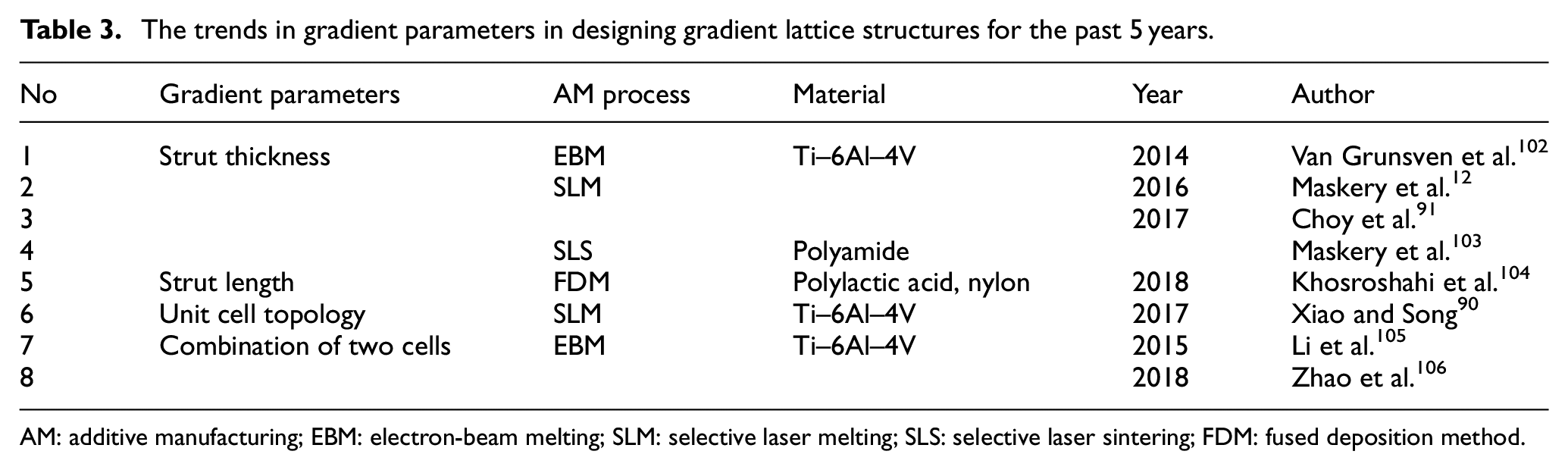
AM: additive manufacturing; EBM: electron-beam melting; SLM: selective laser melting; SLS: selective laser sintering; FDM: fused deposition method.
Applications of GLS
Anisotropic grid-like lattice structure (anisogrid) demonstrates high performance and weight efficiency in rocket technology. Cylindrical and conical structure of thin-walled lattice has been analytically formed and analyzed. Lattice structure is recorded to succeed in reducing 30% weight reduction than a rib-stringer. 5 In conical structures, the size of the unit cells decreases as it approaches the small end shell and increases in size as it approaches the larger end. 107 This conformal-gradient property is to produce localization stiffness in the shell.
Besides aircraft and spacecraft, GLS contribute in biomedical applications especially in bone implants. The gradient properties across the structure offer a localization density and stiffness of the implant. 108 Wang et al. 53 designed graded density porous 3D hip implants. One type of unit cell, tetrahedron with BCC in the middle of the unit cell was analyzed by scanning and numerically produce arranged frictionless hip implants that will connect the femur and hip bone (Figure 9). Based on the finite element analysis (FEA), higher stress occurred in the middle than the edge of the implant structures. Hence, larger struts’ diameter of unit cells in the middle and smaller struts’ diameter of unit cell at the edge were constructed via SLM using titanium-based alloy.

Hip implant titanium alloy tetrahedron–based GLS manufactured via selective laser melting.
It is well known that complex structures are best to fabricate using AM. In the next section, we discuss the type of AM that are able to manufacture lattice structure and the limitations of the processes and how it affects the mechanical behavior of the lattice structure.
Mechanical behaviors of GLS
The GLS outperforms ULS. 12 To prove the statement, a series of experimental tests is reported in the literature to address this hypothesis and various results have been obtained from the experiment. From previous literature, the most significant difference of mechanical behavior in GLS compared to ULS can be observed from the collapse structure, stress–strain curve patterns, first maximum compressive strength, and energy absorption properties.
Deformation behavior
The pattern of collapse structure for GLS was observed from compression tests performed in past studies.45,90,103,105,108 For an example, Xiao and Song 90 conducted analysis of the rhombic dodecahedron GLS with various unit cells that underwent a quasi-static compression test. The GLS with small unit cell size at the top layer and large unit cell in the bottom layer is labeled as positive gradient whereas the GLS with large unit cell size at the top layer and smaller unit cell size in the bottom layer is labeled as negative gradient. The positive GLS is observed to have a significant initial collapse at the bottom layer, which is contradictory in the negative GLS where the initial collapse happened at the first layer of the structure. This proves that when plastic deformation occurs, strain emerges in the layer with high porosity.
A similar case appears in functionally graded porous scaffold where initial buckling occurs at the high porosity bottom layer of the structure. 108 Low density with high porosity regions are located at the bottom layer of the cubic and hexagonal GLS thus providing another identical case. 45 The bottom region for both GLSs deformed first followed by the next layer gradually.
Two more comprehensive studies in GLS collapsing regions have been proposed where the case is almost similar to each other. Maskery et al. 103 arranged their lattice structures the other way around from the previous researcher. The bottom layer of the BCC GLS has high density and low porosity. And the first layer of the BCC GLS has the thinnest strut diameter resulting in the lowest density and high porosity. Different GLS behaviors were observed where strain localization emerges from the top to bottom layer sequence. Novel GLS behaviors were observed where strain localization, plastic deformation, and plastic collapse emerged in layer-by-layer sequences starting from the first layer. From Figure 10(a), compared to GLS, diagonal cracks were observed on the initial deformation of ULS.

Collapse deformation behavior of (a) ULS and (b) GLS.
Different arrangements of GLS were studied by Li et al. 105 which are low–high–low–density regions of rhombic dodecahedron lattice structure graded in the x-direction. The compressive response initially occurred uniformly in the horizontal direction and then a 45° diagonal crack occurred at the low-density region first, followed by the high-density region gradually.
Stress–strain characteristics
The stress–strain properties of ULS behaved differently than GLS. Figure 11 shows the differences of stress–strain curves for FEA and compressive experiments for ULS and GLS F2BCC lattice structure (progressive strut thickness from low density at the first layer to higher density to the bottom layer) in a single graph. ULS behaves homogeneous and linear with long plateau zones which have almost the same behavior as gradient numerical simulation results.

Difference of compressive stress–strain curves between uniform and gradient F2BCC lattice structures.
As for the compressive experiment results, the deformation layer-by-layer is clear for both ULS and GLS. The first maximum local value for ULS is higher than GLS because the first collapse occurred at the highest relative density thus forming two 45° shear bands while for GLS, it occurred at the lowest density at the first layer producing a low value of the first maximum local.
Kadirgama et al. 94 recorded a longer elastic deformation occurring at 70% volume porosity compared to 95% volume porosity of ULS in the compression stress–strain curves. A small region of elastic deformation of 95% volume porosity (lower density) resulting in larger shear deformation occurred before the collapse. The initial maximum compressive strength and energy absorption behavior shows a distinct behavior between ULS and GLS. The initial maximum compressive strength value can be determined from the first local maximum of the stress–strain curve.
Compressive strength
Previous researches showed there is a difference in initial maximum compressive behaviors between ULS and GLS. The initial maximum compressive stress for ULS is higher than GLS which is understandable because the failure starts at a random position of the strut in the structure. 91 The randomness position usually in the form of diagonal cracks or horizontal cracks along the y-axis is due to the relatively high density while for GLS, first maximum compressive strength occurs at the lowest relative density of the structure. Al-Saedi et al. 23 recorded the ULS F2BCC forming 45° shear band failure at 6% strain. An experimental comparison was conducted and found ULS showed 20 MPa of initial maximum stress value while GLS only peaked with 7.5 MPa.
Choy et al. 91 achieved an agreement where both cubic and hexagonal ULS have higher first maximum compressive strength compared to GLS. They repeated the experiment for the lattice structure except for the fabrication which was done using EBM rather than SLM. 109 The same behavior of deformation was recorded. Table 4 shows clear comparison between the collapse behavior, stress–strain characteristics, and compressive strength of GLSs. Here, we can observe that the future study should focus on the stiffness reduction of GLS and compare the pattern with ULS.
Recent studies on the mechanical behavior of gradient lattice structures.

GLS: gradient lattice structures; ULS: uniform lattice structures.
Energy absorption
Lattice structure fabricated via AM is recorded to have good energy absorption properties.48,93,110,111 This has also been explored in prior studies of GLS since the structure collapses progressively layer-by-layer (discussed in section “Deformation behavior”), and hence offering great absorbing qualities. Energy absorbing properties are characterized by numerically integrating the stress–strain curves. 12 Al-Saedi et al. 23 stated that the GLS absorbed a higher amount of energy as compared to ULS even though it is tied to the deformation of the layers.
Cumulative energy absorption per unit volume, Wv, of GLS is observed to be lower than ULS at low strains. 12 After the low-density cell deformed, the deformation of higher density occurred at GLS and it responds to absorbing the same amount of energy to ULS during 52% strain.
Fatigue assessment in additively manufactured lattice structure
Fatigue is defined as the effect of load repetition on lattice structure that leads to failure. Fatigue failure happens in three stages: crack initiation stage, crack propagation stage, and final fracture for both compressive and tensile tests. 112 Fatigue analysis of lattice structure can be used to determine its life cycle. The effect of unit cells topology on fatigue strength has been investigated.57,113 Speirs et al. 113 designed an experiment for orthopedic implant applications and found that the fatigue strength of ULS Nitinol (NiTi) sheet gyroid lattice structure outperforms the ULS gyroid lattice structure. The continuity of topology topography of sheet gyroid (Figure 12) helps to minimize the staircase effect and reduce the stress concentration on the surface. The decrease of the staircase effects can reduce a sudden change in the structure’s topography resulting in low crack initiation possibility. Zargarian et al. 57 reported that truncated cuboctahedron has a better fatigue performance compared to rhombic dodecahedron and diamond lattice structure. In this case, this is because Zhao et al. 114 stated that cubic structures inherit high fatigue strength compared to G7 and rhombic dodecahedron lattice structures even though the surface structure of cubic is coarser.

Unique unit cell and lattice structure of sheet gyroid with continuous surface topography.
However, Van Hooreweder and Kruth 30 stated that surface structure gives high impact on fatigue resistance. SLM manufactured Ti6Al4 V diamond lattice structure that underwent hot isostatic pressing (HIP) and chemical etching (CE) treatment showed a positive effect in the fatigue performance compared to the as-built lattice. The heat treatment reduced the porosity of the surface and increase ductility. Wauthle et al. 115 suggested that as the ductility of the structure increased, the fatigue life cycle is expected to increase too. On the contrary, Dallago et al. 116 deduced that HIP treatment does not show any significant effects on fatigue resistance even though it succeeded in reducing internal porosities. The fatigue crack in the strut section originated from surface irregularities which lead to high stress concentrations rather than internal pores.
The building orientation could give a huge difference in fatigue performance. Pérez-Sánchez et al. 117 studied the effects of building inclination of electron beam–melted Ti–6Al–4V struts for fatigue strength. Two different inclinations: 45° (oblique) and 90° (vertical) from the horizontal plane of 1.0 and 0.6 mm of 15-mm cylindrical strut (total four specimens) underwent three-point bend tests to study their fatigue performances. The vertical 0.6-mm strut is said to be the lowest fatigue performance when 106 cycle is reached by only 15% flexural strength while other struts can manage up to 20% and 25% flexural strength. They concluded that oblique inclination has the best fatigue behavior compared to vertical orientation strut.
Recent studies of fatigue behavior of graded/GLS has been discussed by Zhao et al. 106 where two types of GLS are proposed. First, the GLS varied in unit cells and three different angles of rhombic dodecahedron in the x-direction. Fatigue strength increased progressively from small unit cell to large unit cell. The main reason smaller unit cells have the lowest fatigue strength is because the increased buckling structure upon the increase of load applied. The second type of GLS studied is dual layer cubic-G7 lattice structure known as graded mesh where cubic is the hard constituent with high strength and G7 is the low constituent with low strength properties. The fatigue crack initiation started at the hard constituent first mainly because of the buckling and low cyclic ratcheting rate.
The fatigue analysis for GLS needs to be studied more in the future work. The increasing of strut diameter continuously layer-by-layer (section “Strut thickness”) in GLS is expected to provide high fatigue strength since the failure of fatigue in cellular structure is dependent in struts failure. 57 Besides, the destructive pattern between ULS and GLS is so different in terms of collapse structure and first maximum compressive strength could also affect the fatigue behavior of GLS.
Manufacturability of lattice structures for AM
Manufacturing GLS
AM is widely used for fabrication of porous structures using SLM and EBM for metallic parts and selective laser sintering for non-metallic parts. 118 Figure 13 shows a brief step-by-step methodology to build lattice structures starting from designing the 3D CAD model to the final post-processing step.

Flowchart of chronological manufacturing process of lattice structure using AM technology.
The manufacturing process starts with a 3D CAD model designed using any suitable CAD software. 119 The file is then transferred to software connected to the AM machine in .stl (stereolithography) file format. Magics software is often used by researchers,30,80,82,120 and it is the most suitable software to control the building direction of the structure during the pre-processing step. Next, the construction of support structure for overhanging angles and required support to hold the parts during the fabrication process 121 are usually done using the Magics software. 122 When the parts are ready, and the support is completely built, the fabrication process can be started. For GLS, most researchers choose SLM or EBM technology because GLS parts produced by AM has less defects and sometimes no defects or broken cells. 11
Since lattice structure contains hollow forms throughout the volume, designers need to be aware of minimum size constraints especially strut size and pore size to ensure no blockage. CE can be done to remove powder from lattice structure if needed. 123 The excessive powder is then used for the next production to reduce metal powder wastage. 38
The purpose of the heat treatment is to increase the ductility and reduce the pores of the surface of strut. Previous research showed that heat treatment process could enhance the endurance limit. 124 Wauthle et al. 115 recorded a small reduction in relative density of diamond lattice structures after heat treatment. They also found that even though high-pressure heat treatment was conducted, there were still pores present on the structure. However, DebRoy et al. 125 stated that heat treatment at post-processing is necessary to achieve homogeneous microstructures. The necessity of post-processing heat treatment is highly dependent on what the model is used for.
The final step is accuracy test. The manufacturing geometry is inspected using accuracy test to ensure the product is manufactured in good condition and the entire model’s geometry followed the simulation’s geometry accordingly. Besides, dimensional accuracy test needs to be performed to detect defects and failures upon manufacturing.
In 2016, Alsalla et al. 89 used a computed tomography (CT) scan to scan the lattice structure and reported a small relative density decrease due to the presence of pores inside the solid struts. In 2018, Kadirgama et al. also used the same type of scanner and found that the sample had expanded 2.92% from the CAD model size. However, all the trusses of Ti–6Al–4V lattice structures have a similar thickness. 94 Jetté et al. inspected their ordered porous stem and found unmelted powder of the building material in the lattice structure. However, even though it may raise a series of risks, but the presence of the residual powders do not affect the mechanical properties significantly. 34 However, even though design freedom is achievable when using AM, there are still limitations and constraints in manufacturing lattice structures that need to be considered before the fabricating process.
Lattice structure manufacturing constraints
Despite many advantages offered by AM in manufacturing lattice structures, there are a few drawbacks that need to be addressed. A complex lattice structure with overhang areas needs support structures to ensure an accurate building process. Figure 14 126 shows a support structure under the lattice ball. Since been reported in the previous literature, 127 layer-based processes need supports to prevent the molten metal inside the powder bed collapsing when building large overhanging layers. Support structures are built in the pre-processing phase and made from the same type of material from the part. SW Killi 128 in his book “Additive manufacturing: design, methods and processes” stated that support is needed if the strut angle in lattice structure is below 45° from the horizontal surface.

Support structure under the lattice model.
In 2014, Yan et al. 61 stated that strut angles below 30° and large cell sizes of lattice structure could not be manufactured using SLM without the presence of support structures. The strut angle could become an overhang strut and will lead to manufacturing failure without the use of supports. Besides, the use of supports is needed for heat dissipation and to rigidify the part to prevent distortions. 81 However, the requirement of support should be minimized because when removing the support structure, it could cause damage to the product. 129
There are several other limitations recorded when using the AM process. Leary et al. 19 stated the limitations of SLM that include powder size, material type, and process parameters. In 2020, Flores et al. 3 proposed design guidelines for metal powder bed fusion (PBF) systems to minimize the requirement of support structures and reduce time and manufacturing cost. In the same year, Zhang et al. 130 discussed unfavorable issues such as internal defects and oxidation when using an EBM machine.
In the latest research, Sing et al. 95 discovered that lattice structure’s strut dimensions of the manufactured model are larger than the CAD model. The melted pool size is larger than the strut dimension causing expansion in strut size. Besides, it could also be caused by partially melted metal powders that are bonded together with the struts during the manufacturing process. In the process of manufacturing lattice structures, designers should carefully identify the melt pool size, metal powder size, parameters, support structures, the oxidation amount to reduce defects and control the time consumed as well as the manufacturing cost.
The capability of AM to manufacture lattice structure opens a huge opportunity for researchers to explore more types of lattice structures and experiment their mechanical behaviors. However, design structures and AM parameters need to be considered before designing to limit the manufacturing constraints.
Conclusion
GLS has brought a huge opportunity in designing lightweight and strong parts. The study of GLS has reported increase each year because the metallic AM offers almost zero design limitations. This article presents a review on GLSs and their mechanical behaviors, design, and the manufacturability of lattice structure as well as their limitations using AM.
In conclusion, this article provides a good starting point for discussion and analyzes the trends in the integration of GLS in AM parts and shows that further research in the field is required and is an interesting topic for future work. The trends show that there is an increase for the last 10 years in GLS applications in the industry, for example, in biomedical, aerospace, and automotive industries. The design and application of GLS can be expanded and widely used to manufacture high performance parts for various industries. Future research should consider varying the strut shape or combining materials used to form new types of GLSs. In addition, various GLS characteristics need to be studied and is an important area for future research, such as combining two or more types of GLS, for example, varying the strut diameter and combining two or more types of unit cells that enhance the mechanical performance and multifunctionalities of the structure. GLS has high potential in manufacturing high performance lightweight parts and can become the future of porous structure.
Footnotes
Handling Editor: James Baldwin
Declaration of conflicting interests
The author(s) declared no potential conflicts of interest with respect to the research, authorship, and/or publication of this article.
Funding
The author(s) disclosed receipt of the following financial support for the research, authorship, and/or publication of this article: The authors thank the Ministry of Education Malaysia for funding this work within the project FRGS/1/2018/TK03/UKM/03/1.