
Abstract
Used in several industrial fields to create innovative designs, topology optimization is a method to design a structure characterized by maximum stiffness properties and reduced weights. By integrating topology optimization with additive layer manufacturing and, at the same time, by using innovative materials such as lattice structures, it is possible to realize complex three-dimensional geometries unthinkable using traditional subtractive techniques. Surprisingly, the extraordinary potential of topology optimization method (especially when coupled with additive manufacturing and lattice structures) has not yet been extensively developed to study rotating machines. Based on the above considerations, the applicability of topology optimization, additive manufacturing, and lattice structures to the fields of turbomachinery and rotordynamics is here explored. Such techniques are applied to a turbine disk to optimize its performance in terms of resonance and mass reduction. The obtained results are quite encouraging since this approach allows improving existing turbomachinery components’ performance when compared with traditional one.
Introduction
Dynamic optimization methods are a gold standard in the turbomachinery field especially devoted to increase rotational velocity and, at the same time, to reduce components mass. Moreover, it is possible to increase the safety range of a component under operating conditions simply by changing its natural frequencies. Optimization methods are usually classified as follows (Figure 1):2,3 parametric optimization (where the size of considered elements changes during the optimization routine), 4 shape optimization (where the shape of the structures is subjected to modifications during the optimization),5,6 and topology optimization (TO). 7

An example showing different methodologies for optimizing structures: sizing, shape, and topology optimization. 1
Despite TO methods are commonly used for civil applications 8 and for optimizing automotive components, 9 they have not been fully explored in the turbomachinery field. 10 Nevertheless, they have been regarded among “the most challenging and promising methods in structural optimization.”11–15 In fact, TO is a method “able to determine the best distribution of material once an optimization function is defined together with a set of constraints.” It works starting from a solid block of material whose material is removed to minimize or maximize the optimization objective function (OF). 1 In other words, TO allows a topology modification of the examined structure so that the optimal design can be achieved to be compliant with a certain set of loads, boundary conditions, and constraints. 16 It also allows creating a component described lattice structures characterized by low-mass, high impact energy absorption and high degree of design freedom.17,18 TO problems are usually confronted with the so-called solid isotropic material with penalization (SIMP) method, that is, a structural procedure where a parameter, named pseudo density, is applied to each cell of a polygonal or polyhedral mesh approximating the geometry of the component. 19 In detail, the material density is set to a value in the range [0, −1]; 0 denotes the so-called void state and 1 defines the so-called solid state. 20
Other related methods aiming to solve the TO problem are in literature. In Guo et al., 21 a method allowing TO is proposed. Optimization is based on the concept of moving morphable components. In Gao et al., 22 a TO methodology is presented. In such a work, both the shape and topology of a structure can be simultaneously retrieved using an explicit boundary description and evolution algorithm. In these approaches, TO can be carried out in a geometrically explicit way, and size, shape and TO can be integrated perfectly. Moreover, both the number of design variables and degrees of freedoms (DOFs) for structural response analysis can be reduced substantially.
In this work, optimization is obtained using the so-called lattice structural optimization (LSO). Traditionally, this method allows achieving a solution using a two-step procedure:
Step 1. Performing a conventional TO where three density values (low, intermediate, or high) are associated with the component. Low and high values are related to, respectively, void state (value equal to 0) and solid state (value equal to 1). The intermediate density is defined by all intermediate values falling in the range [0, 1].
Step 2. Optimization of the geometry of areas characterized by intermediate values; these are transformed into a lattice structure whose lattice member dimensions reach an optimized value.
By implementing both optimization steps, which constitute the core of lattice-based optimization (LSO), it is possible to create a structure where lattice components are linked to solid parts.
The result of this two-step optimization consists of a structure blended with solid parts and lattice zones. LSO works by setting different external loads, by imposing a set of boundary conditions, and by defining an appropriate optimization function (typically in terms of volume or compliance). Moreover, a set of optimization constraints in terms of stress and/or volume fractions has to be defined. The manufacturability of components whose shape is obtained by carrying out LSO cannot be conveniently exploited using traditional subtractive techniques. Fortunately, such a manufacturing restriction can be overcome by using additive manufacturing (AM). In fact, by creating a part layer by layer, AM allows to design structures having complex geometry, thus allowing to broaden the design space of lattice structures. 23 Consequently, the combination of LSO and AM can be considered a new terrific strategy for designing mechanical components.
Surprisingly, the extraordinary potential of LSO + AM has not yet been extensively investigated to confront with rotating machines. This is a lack in scientific literature since the above-mentioned technique could be capable of retrieving an optimized geometry for both rotor and stator parts.
Based on the above considerations, in this work, the applicability of LSO and AM to the fields of turbomachinery and rotordynamics is investigated. In particular, such techniques are implemented with reference to a simplified turbine disk to modify the initial geometry of the component characterized by a safer behavior in terms of resonance conditions around the frequency of external loads and, at the same time, to reduce its mass. The result consists of a newly designed component which is more efficient and have lower mass, thus resulting as a convenient method also from an economic viewpoint.
Starting from a traditional design of the disk turbine, particular focus is addressed toward the implementation of the LSO approach with the final aim of demonstrating the effectiveness of the lattice-based design with reference to the traditional one. Eventually, AM is used to fabricate a physical mock-up of a portion of the studied disk turbine and to prove the feasibility of the integrated LSO + AM approach.
As further described in the following sections, the disk turbine is subjected to a static external load due to its centrifugal force field. For the present simplified study, the rotational velocity is maintained to a constant value (i.e. the one reached and maintained in operational conditions).
The boundary conditions set for the optimization routine are on the front hub of the disk (tangential bound) and on the rear hub of the disk (axial bound). The OF adopted to carry out optimization (i.e. to be minimized) may be defined according to the following two options: deformation energy (compliance) or the total volume of the disk turbine. In addition, natural frequencies, maximum stress values, and volume fractions are used to limit the TO.
The result of LSO approach consists of an optimized design of the turbine disk (see Figure 3) whose shape and geometry are, as already mentioned, based on lattice structures. Finally, the performance in terms of mass reduction, stress resistance, and vibration behavior of such an optimized design can be compared against the original one (i.e. not optimized) to prove the effectiveness of the proposed method.
Materials and methods
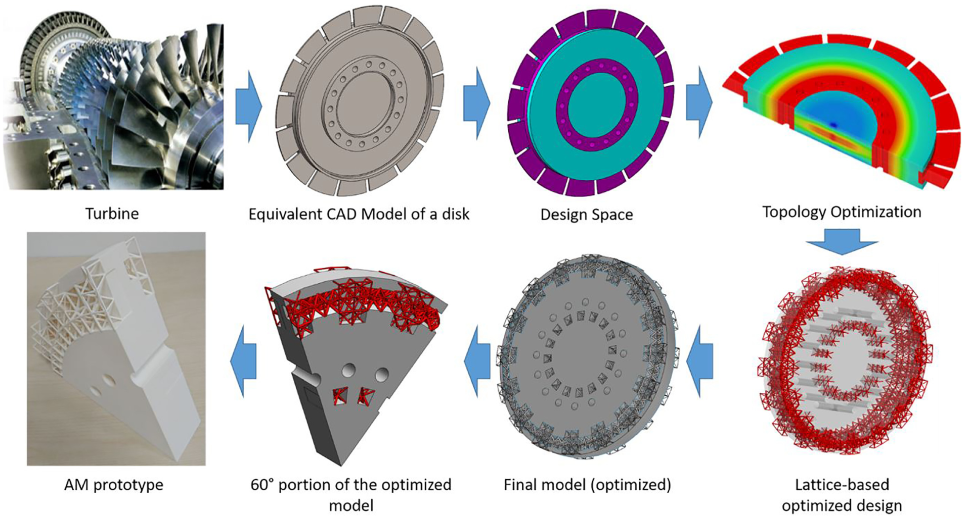
With the aim of investigating the applicability of TO using lattice structures and prototyping a portion of the optimized part by means of AM techniques, a systematic procedure consisting of five steps has been carried out (see Figure 2). The main steps of such a procedure are as follows:
Step 1. Test-case definition: in the present work, the selected case is a turbine disk. The test case includes physical and geometrical features, boundary conditions, and external load. The choice of a test case allows understanding the steps to perform the procedure. Nonetheless, the same approach can be implemented for any other component.
Step 2. Definition of the design space for lattice-based optimization procedure. Such a design space consists of an area whose geometry can be subjected to dramatic changes during the TO routine.
Step 3. Determination of an OF to be minimized during optimization. Depending on the design intent, the OF can describe either compliance or volume.
Step 4: LSO. As mentioned above, LSO allows changing the topology of structures layout first by introducing different values of material density and then by transforming the intermediate areas into a lattice structure.
Step 5. Manufacturing of a portion of the disk turbine using AM techniques. As already mentioned, one of the main aims of this work is to demonstrate the potential of using AM downstream to the optimization process. Therefore, in this work, a prototype of the optimized disk is realized. In fact, the optimized disk is characterized by a complex lattice-based geometry that is practically unrealizable using conventional subtractive technology. Thus, AM is, indeed, the only available technology to realize the disk. However, the current AM technology shall prove to be effective in prototyping lattice shapes. Therefore, this step is crucial to test the feasibility of the proposed method.
General architecture of the proposed procedure.
Using the above-mentioned procedure, a first outcome consists of a structure blending solid parts and lattice zones (at the end of Step 4). Such a structure is a new design of the disk turbine whose geometry is completely changed when compared to the one defined in the original design.
To prove the effectiveness of the proposed approach, a comparison in terms of both static and modal performances between the original disk and the optimized version has been carried out. First, numerical static and modal analysis on the test case selected in Step 1 has been performed: obtained results are used as a reference for benchmarking the newly conceived turbine disk. Then, a comparison in terms of weight, natural frequencies, and stress of the optimized design of test case against the standard results is obtained by using the same numerical analysis procedure.
The second result of the proposed method is a prototype of the disk turbine, which is obtained by using AM. Such a model is realized to investigate the potential of AM techniques when dealing with lattice structures. In fact, it is true that AM allows creating objects with complex geometry, but, however, it is not obvious that lattice structures are all achievable by using current technology. Therefore, a feasibility study of the actual capability of realizing complex lattice structures for turbomachinery components has been carried out to enhance AM capabilities and, at the same time, to highlight possible drawbacks.
Test-case definition
Both to provide a more clear description of the proposed method and to validate the procedure, a test case is here used. Such a test case consists of a turbine disk (see Figure 3) with an external diameter equal to 622 mm (excluding the blades). The disk, which has 72 blades, has a maximum allowable axial size (i.e. maximum thickness) equal to 83 mm. The case study was provided by a major Italian company working in the Oil&Gas sector. For reasons of confidentiality, the exact shape (and number) of the blades cannot be disclosed. To take into account the effect of the blades on the impeller in subsequent simulations, an equivalent solution (in terms of dynamic behavior) is shown in Figure 3. No particular issues arise from this simplification of the three-dimensional (3D) model since, as described in the following section, blades are considered non-design areas. An array of through holes

Test case selected to carry out the proposed framework.
The material used to manufacture the rotating component is 34CrNiMo6 steel (as depicted in Table 1), and it is here assumed that the selected material is characterized by elastic isotropic properties (see Table 1).
Turbine disk material properties.

The selected boundary conditions applied to the test-case disk (to be used for finite element analysis (FEA)) are, respectively, the one that tangentially constraints the disk and the ones constraining it axially (see Figure 4).
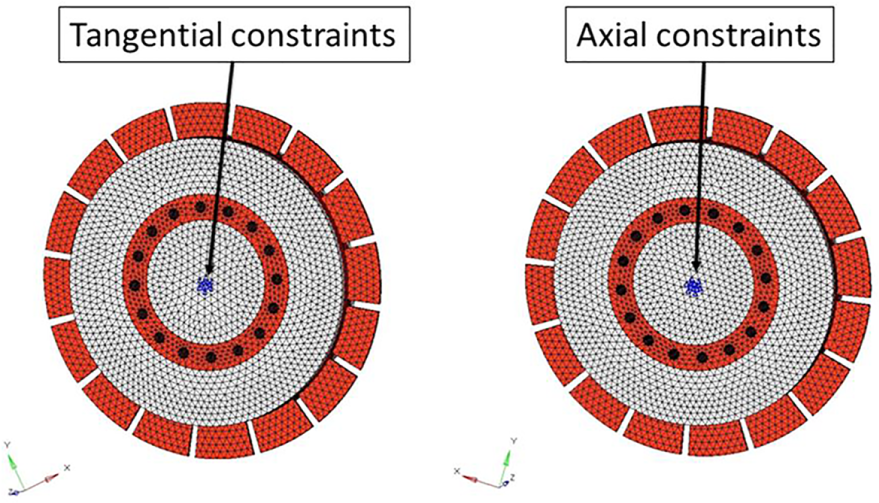
Model constraints.
As previously mentioned, the only load applied to simulate the disk behavior consists of the static centrifugal force field. Operative rotational velocity is set to 10,200 r/min.
Design space for optimization routine
When a generic TO has to be carried out, it is necessary to outline the design space, that is, an area enclosing the set of elements that optimization process can change or remove. In contrast, a non-design space can be defined; this space shall remain unmodified during the optimization routine. Referring to the selected test case, the area around the holes and between the disk and the blades is part of the non-design space. To admit more topologically consistent geometries, the design space is expanded to cover all the allowable axial size (see Figure 5), so that, with respect to the original design of the disk, much material can be “used” during the optimization procedure.

Expanded design space dimensions.
Design and non-design volumes for the entire disk are depicted in Figure 6.

Definition of design and non-design space.
Determination of the OF
To obtain a new optimized geometry, it is necessary to minimize a properly defined OF. Two main optimization strategies can be used to find the optimal topology of the disk turbine: volume minimization and compliance minimization.
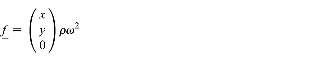
In the first strategy, the overall volume of the design space is considered as OF

where
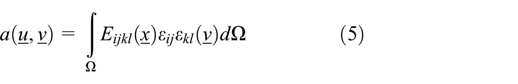
In the second strategy, the compliance, that is, the deformation energy of the structure, is considered as the function to be minimized:

where
With reference to the selected case study, the volume minimization procedure was not able to converge; for this reason, the final geometry of the disk resulted unbalanced. Quite the reverse, compliance-based optimization proved to be more effective in terms of convergence and produced a smooth design of the disk turbine.
Compliance-based optimization consists of finding the material density distribution able to minimize the structure deformation under the provided loading conditions (subjected to a given set of boundary conditions). The optimization constraints are applied both on the maximum value of the stress and on the volume fraction, which is defined as follows

where
In detail, the constraints are
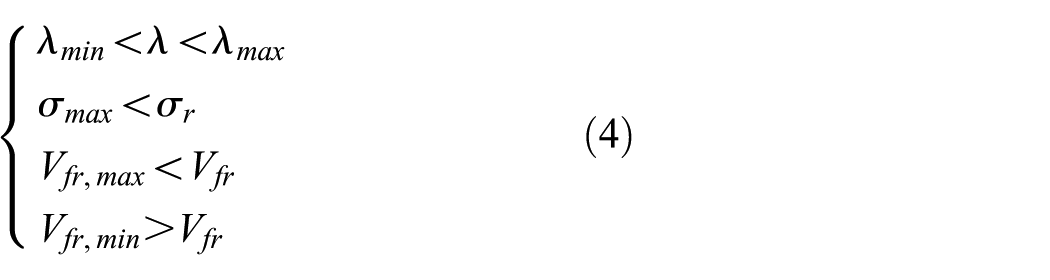
where
LSO
TO
As already mentioned, TO is a method that changes the layout of a given solid part by removing material in areas which are not crucial in terms of external loads and boundary conditions.
24
The design problem can be reduced to the problem of finding, within the domain

where

According to the strain relation reported in equation (7), the material is considered to be linear, isotropic, and homogeneous.
The minimum compliance problem, equivalent to finding the maximum global stiffness (see Figure 7), is expressed by the following equation

where

Generalized shape design problem to decide the optimal material.
This problem can be solved using typical finite element method (FEM) software packages implementing optimization tools. In this work, the OptiStruct tool
20
within the engineering software package Altair HyperWorks has been used. In detail, TO is carried out by implementing SIMP method. In particular, a pseudo material density

where
The

High-, medium-, and low-porosity options for the penalty method.
In this work, the selected value for
With the aim of modifying natural frequencies and, at the same time, to obtain a safe range without normal modes (i.e. to avoid resonance), a preliminary analysis of the normal modes of the standard turbine disk in proximity of the blade alternating force frequency has been performed. Referring to the turbine disk used to test the procedure, such a frequency is equal to
Normal modes around the blade alternating force frequency.

As described in Table 3, normal modes 73 and 74, defined as
Safety margin definition.

Accordingly, the disk geometry shall be changed to shift such modes to different values which are further away from the frequency defined by the blade alternating force. Once all the above-mentioned conditions are stated for the problem, TO can be performed using the selected solver (as already mentioned, in this work OptiStruct has been selected). The data used for constraining the optimization are as follows

The above-defined set of constraints has been determined using a trial-and-error method, since no general rule has been determined for the optimization analysis.
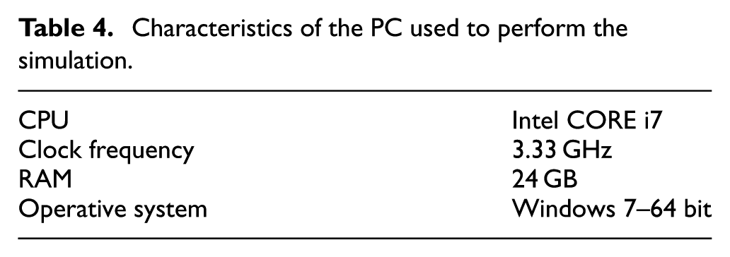
The model of the turbine disk consists of 30,624 solid elements with 45,716 nodes. Each node has 6 DOFs. Processed by using a PC whose performances are listed in Table 4, the optimization procedure converged after about 1000 s.
Characteristics of the PC used to perform the simulation.
The result of optimization routine consists of a disk model where density is properly changed to fulfill compliance minimization (see Figure 9).

Results of the compliance minimization on the selected case study.
Concerning the numerical convergence of the analysis, Figure 10 shows the numerical convergence of the structural optimization procedure in terms of global deformation energy as a function of the iteration number. At each iteration of the optimization procedure, a new finite element analysis is performed by the solver.
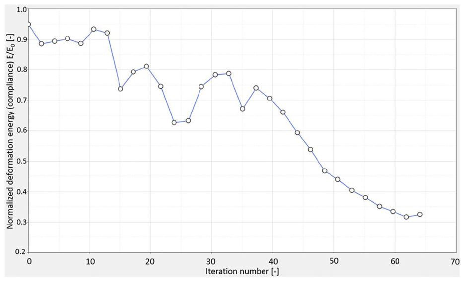
Numerical convergence of the structural optimization procedure.
Lattice conversion and optimization
Once the compliance minimization has been carried out, it is possible to perform the lattice conversion and subsequent optimization.
20
In detail, the optimization allows to specify both the lower bound (LB) and the UB on the density
Elements with densities higher than the upper limit remain solid elements.
Elements with a density between the upper and lower limits are replaced by the corresponding reticular structures; the dimensions of which are optimized during the optimization of the structural grid. 20
Elements with densities lower than the lower limit can be considered as null elements and therefore not involved in the optimized model.

Lower and upper bounds of the element density
The elements of the lattice reticular structure can be considered as mono-dimensional bar elements having the radius proportional to the density of replaced elements. 20 When such a radius is too small, the optimization phase is able to remove the element from the structure. In the proposed routine, the selection of the model mesh typology is an important task. 20 Using tetra elements, for instance, leads to only one possible configuration. Quite the reverse, with hexahedral lattice structures, it is possible to define two different configurations (see Figure 12). By performing a number of optimization tests demonstrated that the first configuration (i.e. the one characterized by LT = 1) of hexahedrical elements gives higher performance results, and therefore, it is the set used in this article.

Influence of the mesh type on the lattice generation.
The mesh dimension is also very important, because it defines the length of the lattice bar elements. The turbine disk is modeled by 54,484 solid elements (type hexa) and has 39,650 nodes with 6 DOFs for each node. The lattice boundaries
The outcome of lattice-based procedure, applied to the case study, is depicted in Figure 13. It consists of a new design of the disk turbine where solid parts are blended together with optimized lattice structures, which replaced the intermediate density area.

Final optimization of the disk turbine selected as a test case for assessing the LSO: (a) final model with highlighted lattice structures and (b) final optimized design of the disk turbine, blending lattice structures with solid parts.
Disk manufacture using AM
As mentioned in the “Introduction” section, one of the main aims of the proposed approach is to discover the potential of AM to design lattice-based turbomachinery components. In fact, the potential of AM technology in supporting lattice structures with a gradual and controlled porosity (not achievable by using conventional manufacturing processes) has still to be demonstrated in scientific literature when dealing with rotor and/or stator elements.
To this purpose, the 3D model of the disk turbine optimized by implementing the LSO has been processed with the final aim of obtaining a 3D prototype using AM. At least, three main issues arise when AM has to be applied on rotating parts whose geometry is described by lattice structures. The first issue is related to the capability of 3D printing process to effectively reproduce the thin lattice structures. It seems obvious that AM can actually realize a turbomachinery component composed of lattice structures; however, this has not been addressed so far in literature and therefore it deserves a practical demonstration. The second issue concerns the behavior of the lattice-based component in terms of fluid dynamics. If on one side it is possible to demonstrate that the optimized component has better performance in terms of weight, maximum stress, and natural frequencies (see section “Results”), it is hard to demonstrate its effectiveness in operative conditions, for example, when subjected to forces coming from fluid stresses. Having the opportunity of investigating a physical prototype could help in assessing fluid dynamics behavior (e.g. by using a wind tunnel). The third aspect, not investigated in this article, is related to the mechanical strength of the overall prototype that should be close to the actual resistance of the standard design. To address all these aspects, a method could be to manufacture the component using several 3D printers based on laser beam melting, electron beam melting, or laser metal deposition, under several printer settings. Then, the best prototype obtained by scouting both the technologies and the machine settings could be experimentally characterized. However, this kind of experimentation involves significant costs related to the actual cost of prototyping metal powders, especially in case the model is realized in full scale and, even worst, in case more prototypes have to be realized prior to obtain the best one. In other words, the above-mentioned approach provides practically inconvenient results. Since, as already mentioned, this work aims to perform a feasibility study on the potential of AM in realizing lattice-based structures for turbomachinery components regardless of the actual mechanical strength of the resulting prototype (i.e. only from a “geometrical” point of view), a different, cost-effective, approach is proposed here.
In particular, the idea is to use a cost-effective 3D printer based on selective laser sintering (SLS) of polymeric materials. Created by 3D Systems Inc., Rock Hill, SC, such a 3D printer “uses a high-power laser to fuse small particles of plastic, metal, or ceramic powders into a 3D object.” 25
The outcome of this process consists of a prototype, realized, for instance, in nylon, with the exact geometry of the optimized computer-aided design (CAD) model. Evidently, being the realized prototype made of polymeric material, it cannot be used to address a mechanical experimentation, that is, it is not possible to compare actual performance in terms of maximum stress of the optimized disk turbine against the performance of the real, traditional, component. However, such a prototype can (1) demonstrate the effectiveness of AM to realize turbomachinery components based on lattice structures and (2) can be used by designers to perform several experimental analyses, for example, to address possible issues coming out from fluid dynamics. In fact, metal-powder-based processes, such as, for instance, direct metal laser sintering (DMLS), are very close to SLS for polymers being the main dissimilarity, of course, in the different material processed; this assure the manufacturability of the component also using metal powders. Furthermore, the nylon-based model is so realistic in resembling the optimized CAD model that it can be effectively used for many design purposes. 26 Finally, the steps for creating the AM prototype starting from the lattice-based model are not straightforward since the AM process itself requires an STL file that is not directly obtainable using Altair HyperWorks.
According to the aforementioned considerations, the first step for creating a prototype of the optimized component consists in converting the 3D model into an STL file to be printed. For this purpose, it is possible to use available CAD converter software packages such as, for instance, Materialize 3-matic (i.e. a software, enabling both design modification and re-meshing, allowing to (re)design topology-optimized data for AM).
Once the STL file is available, a 60° portion of the disk turbine is selected, to reduce the dimensions of the printed object (see Figure 14).

Selected portion of the disk turbine to be printed using laser sintering.
It has to be noticed that by processing the model using Materialize 3-matic or similar software packages, the obtained model is not parametric. Consequently, the extraction of single parts of the model to be further processed, using, for instance, an FEM, is not straightforward. Therefore, a method to convert each model entity in a parametric form is recommended, especially for BAR lattice elements. To this end, an appositely devised routine implementing the method described in Nguyen et al. 27 has been realized in C++.
The technology for printing the model is the EOSINT P 390 by Eos, implementing Laser Sintering. Since the model has been realized using polyamide powder, no supporting structures are required. Consequently, overhang-related issues can be neglected. The part orientation is selected taking into account the main practical considerations as suggested by the VDI 3405/3 standard. 28 First, the warping effect is reduced since the part thickness is approximately constant. In order to achieve a trade-off between part roughness (which is better for surfaces normal to the Z-axis of the device) and accuracy of the cylindrical parts (characterizing both holes and lattice structures), the part orientation is selected so as the surface A of Figure 14 lies parallel to the XZ plane and surface B forms a 45° angle with the Z direction. The final model is in Figure 15.

Printed model of the disk turbine portion.
Results
Using the above-mentioned procedure, two different outcomes are obtained. The first consists of a structure blending solid parts and lattice zones, that is, a new design of the disk turbine whose geometry is completely changed with respect to the original design. The second outcome is a prototype of the disk turbine, obtained by using AM, demonstrating the potential of this technique to physically manufacture complex structures based on lattice. Therefore, in this section, the results obtained both from the numerical comparison between new and traditional designs and from a qualitative analysis of manufactured component are addressed.
Comparison between original and optimized design
The comparison between the newly designed turbine disk, optimized using LSO, and the traditional one is assessed with particular reference to natural frequencies, stresses, and mass reduction. By simulating the optimized design (see Figure 16), it is possible to notice that natural frequencies have changed so that a safer range can be obtained when the simulation is performed near to the resonance condition (see Table 5). The frequency responses in terms of modal frequencies and modes are calculated through standard modal analyses of the whole structure, taking into account the mechanical constraints of the system. More particularly, the model analyses are performed both on the original geometry (see Table 2) and at each step of the optimization procedure (see the final results in Table 5 and Figure 16).

Comparison between the benchmark test and the optimized model, in terms of safety margin.
Normal modes nearest to operative conditions of the machine in the optimized model.

In the optimized configuration, in fact,
As reported in Table 5, the structural optimization performed by the authors has moved the modal frequencies far from the frequencies of the external loads (leading to a larger safety margin), but, at the same time, did not substantially modify the shapes of the most important global modes (in terms of amplitude and energy). More in detail, the frequencies of the most relevant global modes may have changed, but their shapes, their amplitudes, and their energies are basically the same. Furthermore, some “secondary” modes may appear or disappear after the optimization, but such modes are not relevant in terms of amplitude and energy; in addition, they are usually local and often related to the bar elements of the optimized lattice structure.
Referring to maximum stress, it can be noticed (see Figure 17) that it resulted lower than the one in the standard disk turbine; in fact, the maximum stress resulted equal to 739 MPa for the optimized part, while the same value for the standard part was found equal to 788 MPa. Finally, the optimized disk has a reduced mass (166 kg) with respect to the original component. A synthesis of the results is proposed in Table 6.

Simulation results: (a) standard disk turbine, (b) 3D element stresses on the optimized component, and (c) bar element stresses on the optimized component.
Comparison between optimized model performance and ground truth.

Qualitative analysis of 3D printed model and actual advantages for the design
The most important requisite the 3D model has to satisfy for demonstrating the potential of AM in realizing lattice-based structures of turbomachinery components is the capability of reproducing the thin lattice elements. Therefore, to assess the quality of the 3D printed model, it is necessary to verify that all lattice elements are built without defects or material superimposition. This can be performed only qualitatively by a visual inspection, verifying that the actual topology of the model resembles the digital design. In the case study presented in this work, the prototyped disk reproduces the correct geometry of the lattice structures, thus suggesting also that the design is presumably realizable using metal-powder-based processes.
Conclusion and future developments
Although still not a praxis in rotordynamics, the combination of combining LSO and AM has the potential to help designers in obtaining structurally efficient and lighter components working safely in a frequency domain far from resonance.
Methods to perform such an optimization were proposed here and applied on a simplified disk turbine to prove their effectiveness. Moreover, the feasibility of AM for realizing lattice-based structure of turbomachinery components has been investigated. According to Carfagni et al.,
26
the availability of a physical prototype can surely help in achieving best results in the design phase, especially when it is necessary to understand the effects on design outcomes, which is derived from the adoption of prototypes across the different stages of the design process. In other words, although the prototype cannot be used to perform an experimentation, it can still provide useful hints for improving the component design. In the optimization phase, in fact, a number of parameters are set prior to converge to the optimized procedure. By changing such parameters (e.g.
Although limited to a single-case study, the proposed method can be easily extended to many kind of components typically used in the turbomachinery field, with particular reference to stator and rotor parts. It can be used even to the whole machine, with the purpose of performing rotordynamics optimization. More possible future research directions are related to the realization of the disk turbine using DMLS to allow actual experimental analysis (structural and fluid dynamics). This could further prove the effectiveness of the LSO approach in designing better rotordynamics elements since it will allow to experiment the obtained prototype in real conditions.
Regarding the future developments of the research activity, from a theoretical viewpoint, the authors focus on the implementation of a more general and multi-physics approach to the optimization of mechanical components. The new approach will be able to integrate structural optimization (including phenomena such as fatigue, wear, cracks, etc.) and fluid-thermal optimization. Currently, the component performances in terms of fatigue and fluid dynamics are only verified “a posteriori” after the optimization through suitable simulations and/or tests on specific prototypes manufactured via AM techniques. In the future, thanks to the new multi-physics optimization approach, such phenomena (fatigue behavior, fluid dynamic and thermal aspects, etc.) will be considered directly “a priori” into the optimization procedure (as optimization constraints or into the functionals to be optimized). In this way, also complex multi-physics phenomena (as, for example, the flutter) will be taken into account during the optimization process.
From an experimental viewpoint, the experimental validation of the proposed strategy will be taken into account. In the next step of the research activity, after this feasibility study and once the components are manufactured in high-resistance alloy, specific tests on the final geometries will be performed to verify the performances of the new components. The tests will concern both the structural resistance and the fatigue behavior of the components. During such tests, the prototypes of the new components will be compared to similar components having analogous mechanical and fluid-dynamical performances but manufactured through standard techniques. In this way, the strengths and the weaknesses of the new design strategy will be better highlighted.
Footnotes
Appendix 1
Handling Editor: James Baldwin
Declaration of conflicting interests
The author(s) declared no potential conflicts of interest with respect to the research, authorship, and/or publication of this article.
Funding
The author(s) received no financial support for the research, authorship, and/or publication of this article.